Perform the folowing test to see if you can come up with anything. After removing the distributor, ensure the rotor is turning while cranking engine. Hope it is not a bad timing belt.
NOTE:
Before proceeding with ignition system testing, check for DTCs
stored in PCM memory.
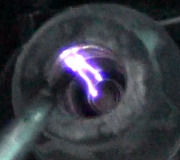
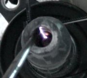
Spark Check
1. Crank engine. Using a high output spark tester, test for a strong, Blue spark at each secondary ignition plug wire. If spark is not as described, go to next step.
2. Verify resistance of each spark plug wire is not more than 25,000 ohms at 68°F (20°C). Check inside distributor cap and rotor for rough or pitted terminals. Check distributor cap for cracks, wear and damage. Repair or replace as necessary.
3. Disconnect and inspect all related ignition system connectors and harness. Clean or repair as necessary, and recheck spark. If strong Blue spark is still not present, go to IGNITION CONTROL MODULE INPUT TEST.
Ignition Control Module Input Test
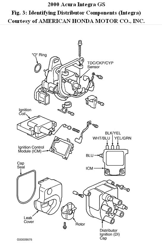
1. Turn ignition off. Remove distributor cap and rotor. Disconnect Black/Yellow, White/Blue, Yellow/Green, and Blue wires from Ignition Control Module (ICM). Turn ignition on. Check for battery voltage between ICM Black/Yellow wire and ground. If battery voltage exists, go to next step. If battery voltage does not exist, check for an open in Black/Yellow wire between ignition switch and ignitor wiring harness connector.
2. Turn ignition on. Check for battery voltage between ICM White/Blue wire and ground. If battery voltage exists, go to next step. If battery voltage does not exist, check for an open in White/Blue wire. If White/Blue wire is okay, substitute a known-good ignition coil.
3. Turn ignition off. Disconnect PCM 32-pin harness connector. Check for continuity in Yellow/Green wire between PCM harness connector and ICM. If continuity exists, go to next step. If continuity does not exist, repair open in Yellow/Green wire.
4. Check for continuity between Yellow/Green wire and ground. If continuity does not exist, go to next step. If continuity exists, repair short to ground in Yellow/Green wire.
5. Connect PCM 32-pin harness connector. Disconnect instrument cluster 13-pin harness connector, Transmission Control Module (TCM) 26-pin harness connector, and cruise control 14-pin harness connector. Check for continuity in Blue wire between ICM and tachometer. If continuity exists, go to next step. If continuity does not exist, repair open in
Blue wire.
6. Check for continuity between Blue wire and ground. If continuity exists, repair short to ground. If continuity does not exist, wiring is okay. Replace ICM.
Ignition Coil Test
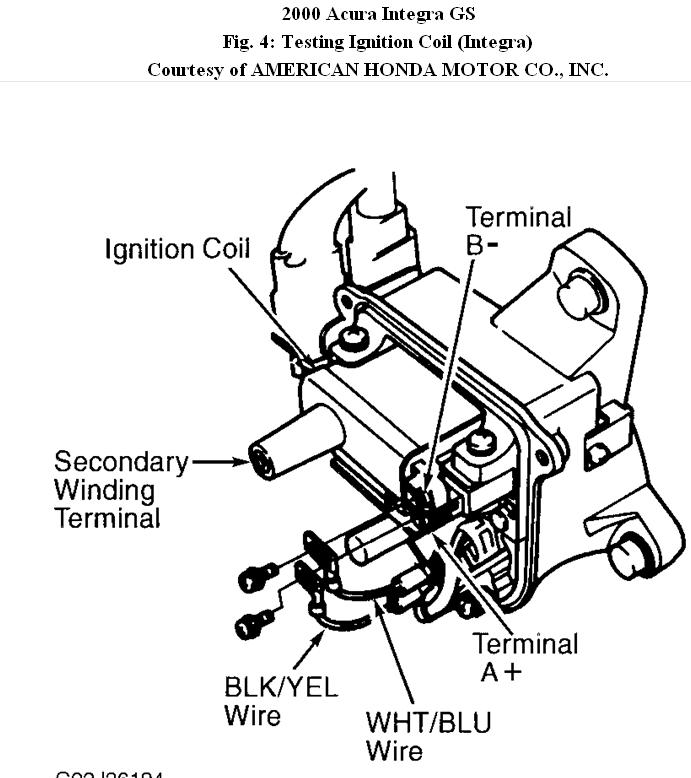
1. Turn ignition off. Remove distributor cap. Remove screws and disconnect Black/Yellow and White/Blue wires from coil. Measure primary winding resistance between primary terminals "A+" and "B-" on ignition coil. See Fig. 4. Resistance should be.6-.8 ohm at 68°F
(20°C).
2. Measure secondary winding resistance between coil terminal "A+" and secondary terminal (coil tower). Resistance should be 12,800-19,200 ohms at 68°F (20°C). Replace coil if resistance is not within specification.
Images (Click to make bigger)
Saturday, November 20th, 2010 AT 12:23 PM