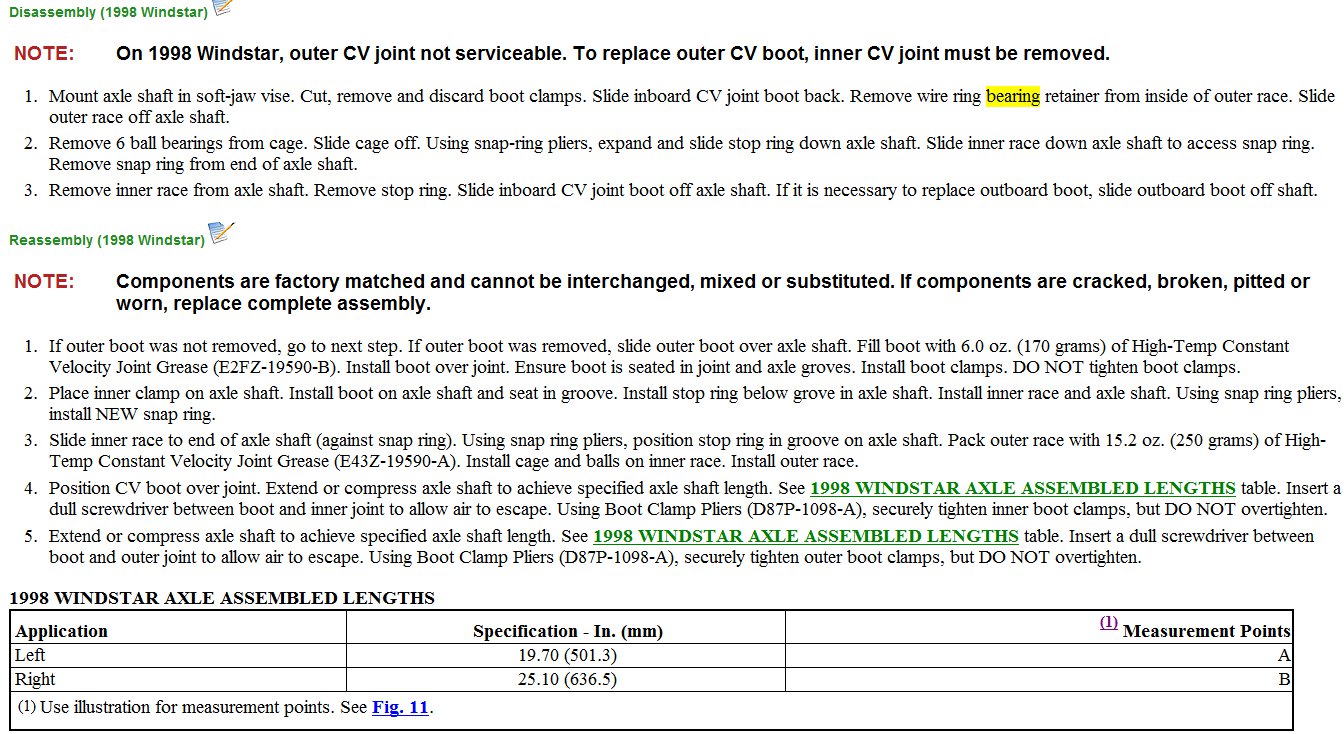
AXLE SHAFTS - FWD -1998 Ford Windstar
Page 1 of 1
AXLE SHAFT (WINDSTAR)
Removal (Axle Shaft Assembly)
1.
Raise and support vehicle. Remove wheel assembly. Remove axle nut and washer. Discard nut. Remove anti-lock sensor retaining bolt, and position aside. Remove lower ball joint pinch bolt and
nut, and discard. Separate ball joint from steering knuckle.
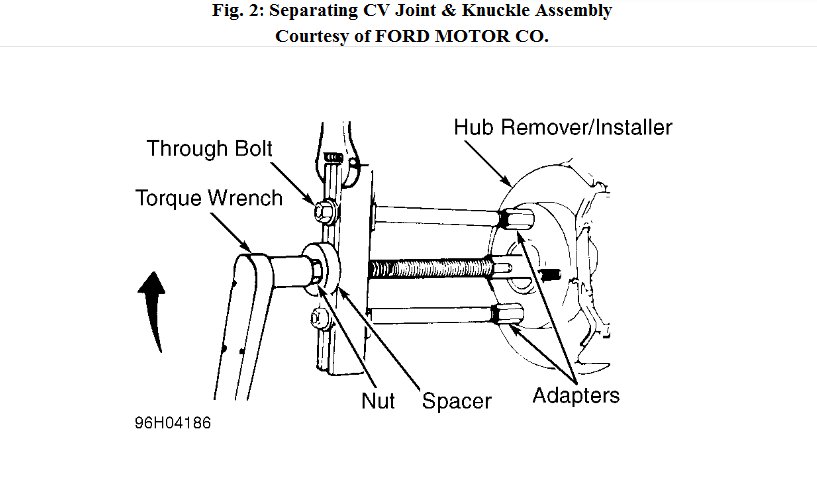
If necessary, disconnect stabilizer bar at control arm. Install Hub Remover/Installer (T81P-1104- C) assembly, and push CV joint out of hub assembly. See Fig. 2. Using pry bar, separate inner
joint from transmission. Remove axle shaft from vehicle.
2.
Fig. 2: Separating CV Joint & Knuckle Assembly Courtesy of FORD MOTOR CO.
Installation
1.
Replace circlip on transaxle end of axle shaft. Insert axle shaft into transmission. Ensure circlip is fully engaged in transaxle. If difficulty is encountered engaging axle shaft into transmission, tap
on outer CV joint with plastic or rubber mallet.
2. Feed outer CV joint stub shaft into hub as far as possible. To complete installation, reverse removal procedure using NEW axle nut and NEW lower ball joint pinch bolt and nut. Tighten all
nuts and bolts to specification. See TORQUE SPECIFICATIONS.
© 2008 Mitchell Repair Information Co., LLC.
FRONT SUSPENSION -1998 Ford Windstar
Page 1 of 2
HUB & WHEEL BEARINGS
Removal (1998)
Remove steering knuckle. See STEERING KNUCKLE . Ensure shaft protector is centered, clears bearing inner diameter, and rests on end face of wheel hub journal. Place a 2-jaw puller and Shaft
Protector (D80L-625-1) on steering knuckle bosses. Separate steering knuckle from wheel hub.
Disassembly
Remove and discard wheel bearing retainer snap ring. Install Front Bearing Spacer (T86P-1104-A2), step side up, on hydraulic press face plate. See Fig. 5 . Put steering knuckle, outboard side up, on spacer.
Install Front Bearing Remover (T83P-1104-AH2) on bearing inner race, and press out bearing. Discard bearing.
Fig. 5: Removing Front Wheel Bearing Courtesy of FORD MOTOR CO.
Reassembly
1.
Clean knuckle bearing bore and hub bearing journal. If hub bearing journal is scored or damaged, replace hub. DO NOT attempt to service hub. Replace bearing if disassembled for any reason.
2. Place Front Bearing Spacer (T86P-1104-A2), step side down, on press plate. See Fig. 6 . Position knuckle, outboard side down, on spacer. Position new bearing inside inboard side of knuckle.
Install Front Bearing Installer (T86P-1104-A3) with undercut side facing bearing on bearing outer surface face. Press bearing into knuckle. Ensure bearing seats completely against knuckle bore
shoulder. Install snap ring.
Place Front Bearing Spacer (T86P-1104-A2) on arbor press plate, and
lugs facing down. See Fig. 7 . Position knuckle assembly with outboard side down on hub barrel. Place Front Wheel Bearing Remover (T83P-1104-AH2) on inner race of bearing, and press until
bearing is seated onto hub. Ensure hub rotates freely in knuckle after installation.
4. Replace bearing dust seal on outboard CV joint with new seal from bearing kit. Use Drive Tube (T83T-3132-A1) and Front Bearing Dust Seal Installer (T86P-1104-A4). Ensure seal flange faces
outboard toward bearing.
3.
position hub on spacer with
Fig. 6: Installing Front Wheel Bearing Courtesy of FORD MOTOR CO.
Fig. 7: Pressing Together Hub & Steering Knuckle Courtesy of FORD MOTOR CO.
Installation
To install, reversing removal procedure. Tighten nuts and bolts to specification. See TORQUE SPECIFICATIONS .
http://www.ondemand5.com/mric/common/asp/printart.aspx
1/20/2012
FRONT SUSPENSION -1998 Ford Windstar
Page 2 of 2
Removal (1999)
NOTE:
Hub and wheel bearing is serviced as an assembly.
1.
Turn ignition switch to OFF position. Ensure steering column is not locked. Remove wheel center cap (if equipped). Remove and discard hub retainer nut and washer. Raise and support vehicle.
Remove wheel assembly.
Remove brake caliper by loosening caliper locating pins and rotating caliper off rotor. Start from lower end of caliper and lift upward. DO NOT remove caliper pins from caliper assembly.
Support caliper aside using wire. Remove caliper anchor plate.
2.
CAUTION: If excessive force is needed to remove rotor, check for excessive lateral runout before installing. Replace as
necessary.
3.
Mark wheel stud to rotor for reassembly. Remove rotor bolts and rotor. If rotor is difficult to remove, apply a rust penetrating lubricant and strike rotor sharply between studs using a rubber or
plastic hammer.
Remove ABS sensor bolt and secure ABS sensor aside. Remove and discard tie rod end cotter pin and nut. Using Pitman Arm Puller (T64P-3590-F), separate tie rod end from steering knuckle.
Remove and discard stabilizer bar link nut. Separate stabilizer bar link. Remove and discard lower ball joint pinch bolt and nut. Using a suitable pry bar, pry between subframe and lower control
arm. Push down until lower ball joint is free of steering knuckle.
4.
CAUTION: DO NOT over-extend drive axle shaft during removal, as CV joint components may separate.
5. Install Hub Remover/Installer (T81P-1104-C) and Adapters (T83P-1104-BH1 and T86P-1104- A1). See Fig. 10 . Ensure hub remover adapter is fully threaded onto lug bolt and is positioned
opposite 2 stud adapter. Support axle shaft. Push CV joint outer shaft until its free of hub, bearing and knuckle assembly. Remove and discard 3 wheel hub retaining bolts and remove wheel hub.
Wheel hub is a slip-fit design and should nut require a puller to remove. Inspect steering knuckle grease seal, hub and bearing assembly for excessive wear and damage. Replace hub and wheel
bearing assembly as necessary.
Installation
To install, reversing removal procedure. Install NEW hub retainer nut and washer, tie rod end cotter pin and nut, stabilizer bar link nut, lower ball joint pinch bolt and nut, and 3 wheel hub retaining bolts.
Install brake rotor and brake caliper. Tighten nuts and bolts to specification. See TORQUE SPECIFICATIONS .
© 2008 Mitchell Repair Information Co., LLC.
Images (Click to enlarge)
Jan 20, 2012 at 11:28 PM