Pulling the MAF would result in the PCM compensating for a faulty MAF and run under a richer condition so that might not be the problem.
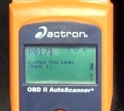
Here are the diagnostics for P0171 and P0174. Check through and see if you can come up with anything.
CIRCUIT TEST H - FUEL CONTROL
Diagnostic Aids
Perform this test when instructed during QUICK TEST or if directed by other test procedures.
Only use this test to diagnose the following:
� HO2S and sensor connection.
� Vacuum systems.
� Fuel injector and/or fuel injector circuitry.
� Powertrain Control Module (PCM).
� Electrical circuits (HO2S, HO2S GND, INJ 1-8, VPWR and SIG RTN).
NOTE:
HO2S may be displayed on scan tester as O2S.
To prevent replacement of good components, be aware the following non-EEC areas may be cause of driveability concerns:
� Ignition system.
� Faulty evaporative emission system.
� EGR and/or PCV system.
� Air intake system.
� Engine oil contamination.
� Fuel system.
� Exhaust system leaks or restriction.
� Engine cooling system.
On all models, SIG RTN is test pin No. 91. VPWR is test pin No. 71 and 97.
NOTE:
Test procedure begins with step 41). No test procedures have been
omitted.
41) DTC P0171, P0172, P0174 Or P0175: HO2S Not Switching
DTCs P0171 and P0174 indicate air/fuel ratio is correcting rich for an overly lean condition. DTCs P0172 and P0175 indicate air/fuel ratio is correcting lean for an overly rich condition.
Possible causes are as follows:
� Fuel system malfunction.
� EGR system malfunction.
� Air intake or vacuum system leak.
� Engine oil level too high.
� Excessive internal engine wear.
Inspect engine for obvious defects in specified systems. Repair or replace as necessary. If no faults are found, go to next step.
42) Perform KOER Self-Test With ignition off, connect scan tester to DLC. Disconnect fuel vapor hose from intake manifold. Plug fitting at intake manifold. Start engine, and operate at 2000 RPM for one minute.
� If none of these DTCs are present, proceed as follows:
If diagnosing DTCs P1171, or P1174, go to step 52).
43) Disconnect suspect HO2S. Turn ignition on. Using scan tool, access HO2S PID of suspect sensor. Connect jumper wire between HO2S SIG and VPWR circuit at HO2S harness connector. If spark occurs, remove jumper wire and go to step 47). If HO2S voltage is more than 1.3 volts, go to next step. If voltage is 1.3 volts or less, go to step 46).
44) Check Circuit Resistance
Turn ignition off. Connect PCM to breakout box. Measure resistance between battery ground terminal and SIG RTN terminal of HO2S harness connector. If resistance is less than 5 ohms, go to step 52). If resistance is 5 ohms or more, go to next step.
45) Turn ignition off. Disconnect PCM from breakout box. Measure resistance between test pin No. 91 (SIG RTN) at breakout box and SIG RTN terminal of HO2S harness connector. If resistance is less than 5 ohms, replace PCM and repeat QUICK TEST. If resistance is 5 ohms or more, repair open circuit and repeat QUICK TEST.
46) Check Resistance Of HO2S Ground Circuits
Turn ignition off. Install breakout box, leaving PCM disconnected. Disconnect suspect HO2S wiring harness connector. Inspect connector for damage and repair as necessary. Measure resistance between HO2S test pin at breakout box and HO2S terminal at sensor wiring harness connector. If resistance is less than 5 ohms, go to next step. If any resistance is 5 ohms or more, repair open circuit and repeat
QUICK TEST.
47) Check HO2S Circuit For Short To Ground
Turn ignition off. Leave breakout box installed and PCM disconnected. Disconnect HO2S. Measure resistance between HO2S SIG circuit test pin and test pins No. 24, 51, 77, 91 and 103 at breakout box. If all readings are 10,000 ohms or more, go to next step. If any reading is less than 10,000 ohms, repair short circuit and repeat QUICK TEST.
48) Check HO2S For Short To Ground
Ensure ignition is off and PCM is disconnected. Reconnect HO2S to wiring harness connector. Measure resistance between HO2S SIG RTN test pin and test pin No. 91 at breakout box. If resistance measurement is less than 10,000 ohms, replace HO2S and repeat QUICK TEST. If resistance is 10,000 ohms or more, replace PCM.
49) Check HO2S PID
Leave ignition off and HO2S disconnected. Turn ignition on. Using scan tool, access HO2S PID of suspect sensor. If HO2S PID voltage is more than 0.2 volts, go to next step. If HO2S voltage is 0.2 volts or less, go to step 51).
50) Check For Short To Power
Turn ignition off. Disconnect scan tester from DLC (if applicable). Disconnect PCM 104-pin connector. Inspect connector for damaged pins, corrosion and loose wires. Repair wiring as necessary. Install EEC-V Breakout Box (014-00950), leaving PCM disconnected. Leave suspect HO2S disconnected. Measure resistance between HO2S terminal of wiring harness connector and following test pins at breakout box:
� DTC P1130 and P1132; test pin No. 60 and test pins No. 71, 93 and 97.
� DTC P1150 and P1152; test pin No. 87 and test pins No. 71, 94 and 97.
If each resistance is more than 10,000 ohms, replace PCM and repeat
QUICK TEST. If any resistance is 10,000 ohms or less, repair short to power and repeat QUICK TEST.
51) Turn ignition off. Disconnect suspect HO2S. Turn ignition on. Using scan tool, access HO2S PID of suspect sensor. If HO2S voltage is more than 0.45 volts, replace HO2S and repeat QUICK TEST. If voltage is 0.45 volts or less, go to next step.
52) Check Fuel Pressure
Release fuel system pressure. With ignition off, install fuel pressure gauge. Ensure manifold vacuum is connected to fuel pressure regulator. Start engine and operate at 2500 RPM. If vehicle will not start, cycle key on and off. If fuel system pressure is as specified, go to next step. If fuel system pressure is not as specified, go to CIRCUIT TEST HC.
53) Check System Ability To Hold Fuel Pressure
With fuel pressure gauge installed, cycle ignition from OFF to ON position 3-4 times to pressurize fuel system (DO NOT start engine). If fuel pressure does not remain at specification for 60 seconds, go to step 4) under CIRCUIT TEST HC. If fuel pressure remains within 5 psi of highest fuel pressure reading for 60 seconds, proceed as follows:
� For no-start vehicles, go to step 55).
� For DTCs P1130, P1150, P0171, P0172, P0174 and P0175, go to step 54).
� For HO2S DTCs displayed with misfire DTCs, go to step 56).
� For all other DTCs, go to step 60).
54) Check Ability To Hold Fuel Pressure
With fuel pressure gauge installed, cycle ignition from OFF to ON position 3-4 times to pressurize fuel system (DO NOT start engine). Note fuel pressure. If fuel pressure remains within 5 psi of original pressure for at least 10 seconds, go to step 56). If fuel pressure drops more than 5 psi, go to step 58).
55) Check Ability Of Injectors To Deliver Fuel
With fuel pressure gauge installed, cycle ignition from OFF to ON position 3-4 times to pressurize fuel system (DO NOT start engine). Note fuel pressure. Disconnect Inertia Fuel Switch (IFS). Crank engine for 5 seconds. If fuel pressure remains within 5 psi (34 kPa) of original pressure, reconnect IFS switch and go to next step. If fuel pressure drops more than 5 psi (34 kPa), repair fuel system as necessary.
56) Check Fuel Injector & Circuit Resistance
Turn ignition off. Disconnect PCM 104-pin connector. Inspect connector for damage or corrosion and repair as necessary. Install EEC-V Breakout Box (014-00950), leaving PCM disconnected. Measure and record resistance between suspected fuel injector circuit test pin and test pin No. 71 and 97 at breakout box.
Resistance should be 11-18 ohms. If resistance is not correct, go to next step. If resistance is correct, go to step 59).
57) Check Resistance Of Fuel Injector Circuit
Turn ignition off. Disconnect suspect fuel injector wiring harness connector. Measure resistance between test pins No. 71 and 97 at breakout box and fuel injector VPWR terminal at wiring harness connector. Measure resistance between fuel injector signal test pin(s) at breakout box and same fuel injector circuit terminal at each fuel injector wiring harness connector. If each resistance is less than 5 ohms, go to next step. If each resistance is 5 ohms or more, repair open circuit and repeat QUICK TEST.
59) Check Fuel Injector Circuit For Short To Power Or Ground
Turn ignition off. Disconnect suspect fuel injector wiring harness connector. Measure resistance between fuel injector test pin and test pins No. 24, 71, 97 and 103 at breakout box. Also, measure resistance between fuel injector test pin(s) at breakout box and chassis ground. If each resistance is 10,000 ohms or more, go to next step. If any resistance is less than 10,000 ohms, repair short circuit and repeat
QUICK TEST.
59) Check Fuel Injector Drive Signal
With ignition off, connect PCM to breakout box. Connect non-powered 12-volt test light between suspect fuel injector and test pins No. 71 and 97. Crank or start engine. If test light glows dimly, go to next step. If test light does not glow dimly (no light/bright light), replace PCM and repeat QUICK TEST.
60) Check Fuel Injector Flow & Leakage
Turn ignition off. Remove breakout box. Reconnect PCM. Use Rotunda Injector Tester (113-00001) to flow test fuel injectors. If fuel injector flow or leakage rate is not okay, replace fuel injector, and repeat QUICK TEST. If flow rate for each fuel injector is okay, proceed as follows:
� For DTCs P0171, P0174, P1130, and P1150, go to step 62).
� For DTCs P1132 and P1152, go to step 65).
� For DTCs P1172 and P1175, go to CIRCUIT TEST Z.
61) Check Secondary Air Injection
If vehicle is not equipped with secondary air injection, go to next step. Turn ignition off. Disconnect secondary air injection hoses. Plug air injection ports. With engine at operating temperature, perform KOER self-test. If DTC P1131 or P1151 are present, reconnect hose and go to next step. If specified DTCs are not present, go to step 7) under CIRCUIT TEST HM.
62) Check air induction system for leaks or restrictions. Check PCV system for leaks or restrictions. Check vacuum hoses for damage and tight connection. Repair or replace as necessary. If no faults are found, go to next step.
63) Check Cylinder Compression
Using compression gauge, check cylinder compression. If cylinder compression is not okay, repair engine as necessary. Clear PCM memory and repeat QUICK TEST. If compression is okay, go to next step (DTCs P1130, P1150, P1131 and P1151) or step 65) (DTCs P1132 and P1152). If misfire DTCs are displayed with fuel control DTCs, go to CIRCUIT TEST HD, step 20).
64) Check HO2S Integrity
DTCs P0130, P0150, P0131, and P0151 indicate HO2S switches slow or doesn't switch, is always lean or fuel is at adaptive limit. Possible causes are as follows:
� Moisture inside HO2S causing short to ground.
� HO2S coated with contaminates.
� HO2S circuit open or shorted to ground.
� Turn ignition off. Inspect HO2S and circuit for damage or contamination. Repair or replace HO2S or wiring as necessary. Start engine and operate at 2000 RPM for 3 minutes. Turn ignition off. Connect scan tool to DLC. Perform KOER self-test while monitoring HO2S
voltage. If HO2S voltage is 0.5 volt or more at the end of test, go to step 70). If voltage is less than 0.5 volt, replace HO2S sensor and repeat QUICK TEST.
65) Perform KOER Self-Test
Start engine, and warm it to normal operating temperature. Turn ignition off. Disconnect suspect HO2S. Using a jumper wire, connect HO2S terminal of wiring harness connector to negative battery terminal. Perform KOER self-test. If DTC P1131 or P1151 is present, remove jumper wire and go to next step. If DTC P1131 or P1151 is not present, check PCM connector and service if necessary. If connector is okay, replace PCM. Repeat QUICK TEST.
66) HO2S Check
Leave HO2S disconnected. Connect DVOM between HO2S SIG terminal and SIG RTN terminal of HO2S wiring harness connector. Disconnect any vacuum hose from vacuum tree. Start engine and operate at 2000 RPM. If DVOM reads less than 0.4 volt within 30 seconds, go to step 70). If DVOM does not read as specified, replace HO2S and repeat QUICK TEST.
NOTE:
A break in step numbering sequence occurs at this point. Procedure skips from step 66) to step 70). No test procedures have been omitted.
70) Monitor HO2S PID
Connect scan tester to DLC. Start engine and allow to idle. Using scan tester, access HO2S PID. Observe HO2S PID while shaking and bending wiring harness between HO2S and PCM. If HO2S voltage stays at 0.45 volt, go to next step. If HO2S voltage is more than 0.45 volt or less than 0.45 volt, isolate fault and repair as necessary.
71)Monitor HO2S PID During Test Drive
Leave scan tester connected to DLC. Using an assistant, test drive vehicle under various conditions while observing HO2S PID. If HO2S voltage switches from about 0.4 to 0.6 volt, system is okay and testing is complete. If voltage does not switch, replace HO2S and repeat QUICK TEST.
NOTE:
A break in step numbering sequence occurs at this point.
Procedure skips from step 71) to step 80). No test procedures
have been omitted.
80)
As voltage change downstream HO2S. Possible causes are as follows:
� Damaged wiring harness or connector.
� Exhaust system leaks.
� Contaminated or defective HO2S.
Inspect for faults. Repair or replace as necessary. If no faults are found, go to next step.
81) Perform KOER Self-Test
Start engine, and operate at 2000 RPM for 3 minutes. With scan tester connected, perform KOER self-test. If DTCs P1137 P1138, P1157 or P1158 are present, go to next step. If specified DTCs are not present, fault is intermittent. Go to CIRCUIT TEST Z.
82) Check Exhaust System
Leaks in exhaust system can cause DTCs P0136 and P0156. Possible causes are as follows:
� Incorrect HO2S torque.
� Exhaust system leaks.
�
Inspect entire exhaust system including catalyst and HO2S. Repair or replace as necessary.
Clear PCM memory and repeat QUICK TEST. If not faults are present, go to next step.
83) Check HO2S Circuit For Short Circuit
Leave ignition off and suspect HO2S disconnected. Disconnect scan tester from DLC. Disconnect PCM 104-pin connector. Inspect connector for damaged pins, corrosion and loose wires. Repair circuit as necessary. Install EEC-V Breakout Box (014-00950), leaving PCM disconnected. Measure resistance between HO2S test pin and test pins No. 24, 71, 90 (VREF), 91 (SIG RTN), 97 (VPWR), and 103 (PWR GND) at breakout box. Measure resistance between HO2S test pin and VPWR test pin at breakout box. If resistance is more than 10,000 ohms go to next step. If resistance is 10,000 ohms or less, repair short circuit in wiring harness. Clear PCM memory.
Drive vehicle for 5 miles and repeat QUICK TEST.
84) Check Ground Circuit Resistance
Leave ignition off and suspect HO2S disconnected. Measure resistance between HO2S SIG test pin at breakout box and HO2S SIG terminal at wiring harness connector. Measure resistance between SIG RTN test pin at breakout box and SIG RTN terminal at wiring harness connector. If resistance is 5 ohms or more, repair open circuit in wiring harness and repeat QUICK TEST. If resistance is less than 5 ohms, go to next step.
85) Check HO2S Circuit
Turn ignition off. Connect scan tester to DLC. Ensure suspect HO2S and PCM are connected. Turn ignition on. Access HO2S PID of suspect sensor. If voltage reading is 1.5 or more, go to step 88). If voltage is less than 1.5 volts, go to next step.
86) Check Circuit Resistance
Turn ignition off. Connect PCM to breakout box. Measure resistance between PWR GND test pin and SIG RTN test pin at breakout box. If resistance is less than 5 ohms, go to next step. If resistance is 5 ohms or more, replace PCM and repeat QUICK TEST.
87) Check HO2S PID
Leave ignition off and HO2S disconnected. Using jumper wire, connect VPWR and HO2S signal terminal of wiring harness connector. Turn ignition on. Using scan tool, access HO2S PID of suspect sensor. If HO2S PID voltage is more than 1.5 volts, replace HO2S. Clear PCM memory. Drive vehicle for 5 miles and repeat QUICK TEST. If HO2S PID voltage is 1.5 volts or less, replace PCM. Clear PCM memory. Drive
vehicle for 5 miles and repeat QUICK TEST.
88) Check PCM Voltage
Leave suspect HO2S disconnected. Turn ignition on. Measure voltage between SIG RTN terminal at HO2S wiring harness connector and negative battery terminal. Measure voltage between HO2S SIG terminal at wiring harness connector and negative battery terminal. If voltage is 1.5 volts or more, replace PCM and repeat QUICK TEST. If voltage is less than 1.5 volts, replace HO2S and repeat QUICK TEST.
NOTE:
A break in step numbering sequence occurs at this point. Procedure skips from step 88) to step 100). No test procedures have been omitted.
100)
QUICK TEST
. If any PIDs are off, operate engine until all PIDs are on; repeat
QUICK TEST.
NOTE:
A break in step numbering sequence occurs at this point.
Procedure skips from step 100) to step 110). No test
procedures have been omitted.
110) Check For Crossed HO2S Circuit
Turn ignition off. Disconnect suspect HO2S. Inspect connector for indication of crossed wires or incorrect installation. Repair or replace if necessary and repeat KOER self-test. If no faults are found, go to next step.
112) Leave ignition off and suspect HO2S disconnected. Disconnect PCM 104-pin connector. Inspect connector for damaged pins, corrosion and loose wires. Repair circuit as necessary. Install EEC-V Breakout Box (014-00950), leaving PCM disconnected. Measure resistance between suspect circuit terminal at wiring harness connector and corresponding
test pin at breakout box. If resistance is less than 5 ohms, fault is intermittent and cannot be duplicated at this time. Repeat
QUICK TEST to verify DTC is present. If resistance is 5
ohms or more, repair circuit. Clear PCM memory. Drive vehicle for 5 miles and repeat QUICK TEST.
Tuesday, April 12th, 2011 AT 9:32 PM