You should start a new question specific to your vehicle, and please be sure to include the engine size and mileage. That helps other people who are researching the same topic. Here's the link if you want to do that. Don't retype everything. Just copy and paste your question if we need to do that.
https://www.2carpros.com/questions/new
Check your Yellow Pages for a local generator / starter rebuilding company in your area. Try the "Automotive Repair", "Electrical" categories. If you can't find it that way, stop in at any car, heavy truck, or off-road equipment dealer's repair department and someone there will be able to point you to such a shop. I have two in my area. One is in a tiny town of less than 3,000 population.
You can also buy these through the Chrysler parts department at any dealership. They might not stock them if they don't have a previous sales history for that part, but they can order it. Also check at the normal auto parts stores. If you still can't find the assembly, run to a pull-your-own-parts salvage yard and harvest one from the lowest mileage vehicle you can find. If you're near Ohio to southern Georgia, and now also to the west, do a search for "Pull-A-Part" to see if there is a yard near you. They used to have 23 yards, and I've been to 16 of them. You can do an inventory search too to see the years and models, but you won't know which engine sizes or other options each vehicle has, or what has already been removed or damaged. These yards are all very clean and well-organized.
The last one of these I did was on my '94 Grand Voyager daily driver. It can be done on the 3.3L engine without removing the alternator from the engine.
1. Disconnect the negative battery cable. (Once reconnected, you will have an idle speed that is too low. You might have to hold the accelerator pedal down 1/4" to get the engine started and to keep it running. We'll cover that later if necessary).
2. Unbolt the three wires from the back of the alternator. One is the large output wire. The two smaller field wires go into a black plastic block that is held on with two small bolts. Don't panic if one of them snaps off due to rusted nuts. Those can be tapped out later, then you can slide in a standard bolt.
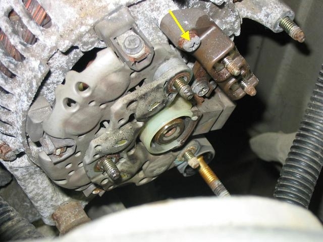
3. This is from memory from a few years ago, so my number of nuts might be wrong. There should be a nut on a round plastic insulator on the output stud. Remove that, and the two or three smaller nuts that hold the rear cover on. The first photo is of the alternator with the cover removed, on my van.
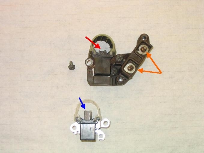
4. Remove the two bolts holding the brush assembly with the terminal block. The yellow arrow is pointing to one of them. Don't try to remove just the three small bolts holding the brush assembly to that terminal block. You'll end up losing them. Slide the assembly off the rotor shaft. It will look like the top assembly in the second photo.
5. Remove the three screws to remove the brush assembly from the terminal block. Now's the time to punch out either of the terminal bolts if they snapped off. The orange arrows are pointing to them. I can't remember if I had to grind the head of the new bolt to fit in a pocket.
The top assembly in the second photo shows what you will have removed. The red arrow is pointing to the brushes that are badly worn. The blue arrow is pointing to the new assembly with non-worn brushes.
6. Bolt the new brushes to the terminal block. You'll need to compress the brushes against spring pressure so you can slide them over the rotor's shaft. Install the two mounting bolts, then check for continuity between the two small terminals. You should find around three to five ohms, plus the few ohms of resistance in your meter's leads. If you find an open circuit, which is not uncommon, irritate the pulley a little by tugging on the belt. Carbon brushes often don't make good contact when the rotor is not spinning.
7. Reassemble the rear cover and connect the wires. I prefer to check my work before connecting the wires to insure I didn't accidentally ground any terminals. Use an ohm meter with the black lead on ground, then check each terminal for continuity to ground. Check them again after the cover is installed. If the output terminal is grounded, you forgot the insulating washer, or the cover is off-center and touching that stud. That will burn open the fusible link when you reconnect the battery cable. If the 12-volt supply field terminal is grounded, it will blow the fuse for the circuit feeding the automatic shutdown, (ASD) relay. That will result in a crank / no-start. If the other small terminal is grounded, the alternator will charge wide-open all the time the engine is running.
8. With the engine running, verify battery voltage is between 13.75 and 14.75 volts. If it is, the system is working properly. To solve the low idle speed, drive at highway speed with the engine warmed up, then coast for at least seven seconds without touching the pedals. That will meet the conditions for the Engine Computer to relearn "minimum throttle", then it will know when it must be in control of idle speed.
Images (Click to enlarge)
Feb 18, 2019 at 4:43 PM