Having problem with a gauge cluster CCD Bus, possibly computer issues?

Tiny
JAULT01
  • MEMBER
  • 1995 DODGE INTREPID
  • 200,000 MILES
I recently installed a heater core in a 95 intrepid for a friend. Had to pull the entire dash of course and after re-assembly the gauge cluster illuminated but none of the gauges worked. SRS, Brake, CEL, turn signals, 4 ways, etc all work.

I disassembled the entire dash again to verify connections and in the meantime I checked the resistance of each wire that ran from the cluster to the bcm or to the junction box, everything checked out with good readings.

I yanked the wire trough, examined each wire from cluster to applicable harness and saw no sign of damage. Grounds are all in good shape, as are "splice points" in the trough.

I installed a used gauge pod that was operative, that puppy still did not read.

Upon yanking the new cluster I checked at the wiring harnesses again, realizing that the CCD BUS(+) and the CCD BUS(-) were not reading at all. The ID SENSE read around 5v, all power read at 12.5. And once again, turn signals, warning lights, and illumination are operational.

The airbag light is stuck on, cruise control is not working. I would assume that this is a failed clockspring, although the horn does still work. I imagine with this year of a car that the horn still would?

Since I am not getting any electrical values from the CCD BUS pins is it possible for that particular channel of the bcm to just have gone bad? Other BCM functions ARE operational. HVAC, light, locks, windows, etc.

Would there be a ground behind the HVAC or even a wiring harness that could have been yanked out? I didnt totally pull the unit out of the car, just pulled it forward enough to reach the core itself.

I also noted this: I went to do a "scan" using the key trick, 2 clicks on and off then one on. There was no response. I am left to wonder if this is all about the ECM? PCM? BCM?

I could really use some advice, I am at my witts end and I have tried to explore this issue for over three weeks. What began as a routine thing to help someone who needed help has become the opposite. Never have I had this type of issue when dealing with a matter that I have done a few times.
Tuesday, January 24th, 2012 AT 2:55 AM
13 Replies

Tiny
CJ MEDEVAC
  • MECHANIC
  • 11,004 POSTS
I SAW YOUR QUESTION FOR A WHILE

YOU DID NOT DISTINGUISH "INTREPID" OR "INTREPID ES"

I DO NOT HAVE A SOLUTION FOR YOU. IMMA JEEP CJ GUY, WHERE THINGS ARE SO MUCH SIMPLER!

I FIGURED I COULD OFFER SOMETHING THAT MAY AID YOU

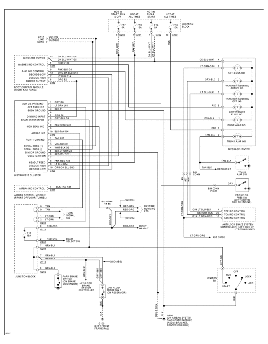
I WENT TO MITCHELL I AND GRABBED "1995 INTREPID INSTRUMENT CLUSTER" WIRE DIAGRAM. LET ME KNOW IF THIS IS CORRECT. OR IF YOU HAVE AN "ES". IF YOU WANT ANY OTHER DIAGRAMS, NAME THE SYSTEM AND I'LL TRY. THERE ARE WELL OVER 60 DIAGRAMS FOR THAT CAR!

IF YOU CANNOT READ THE DIAGRAM. LET ME KNOW.I WILL HELP YOU GET IT SAFELY, WITHOUT BLURTING OUT YOUR PERSONAL INFO IN OPEN FORUM

THE MEDIC
Was this
answer
helpful?
Yes
No
Tuesday, January 24th, 2012 AT 5:47 AM
Tiny
JAULT01
  • MEMBER
  • 51 POSTS
I appreciate your sending me this diagram, I do have a very similar one from All Data. I do understand the flow of the system for the most part, just can not figure out why I have no CCD bus values. Maybe this one can tell me a bit more. I'll have to get back to you as to which model it is. I believe it's a base as it has no anti-theft, no remote start, no message center. It does have power accessories, etc. I will let you know.

I really also need to know why I can't get those codes! The key trick worked for me on a 95 cherokee just a week ago. I wonder if it has something to do with this cluster issue. Thanks for the input!

Jeff
Was this
answer
helpful?
Yes
No
Tuesday, January 24th, 2012 AT 7:06 AM
Tiny
CARADIODOC
  • MECHANIC
  • 33,737 POSTS
Most scanners will have a quick test for the CCD buss. It originates in the Body Computer and you should find 6.0 volts on both wires. That data buss feeds every computer on the car. A short in any computer or anywhere on those wires will kill the buss. If it is indeed shorted, the engine won't start. If it's not shorted but is still dead, check all the inputs to the Body Computer, in particular all the 12 volt feeds and the grounds. Ohm meter results on the ground wires are often inaccurate. Checking for voltage on those wires is a better test.

The Body Computer has a fairly low failure rate, but if you plan on trying a used one it is real important to know that it came from a car that also did not have the factory anti-theft system. That can be almost impossible to figure out with a salvage yard part unless you have some way of knowing its history. If the Body Computer comes from a car with anti-theft, it will teach that programming to the Engine Computer as soon as you turn on the ignition switch. That programming can not be undone. You will have a no-start condition because both computers will be waiting for the disarm signal that is never coming. The only way to solve that is by replacing BOTH computers at the same time with ones from another car without anti-theft. If you replace just the Body Computer again, it will learn the anti-theft programming from the Engine Computer.

I know you didn't mention a no-start condition, but it's good to be aware there have been instances where a voltage spike will trick the computers into self-programming themselves for the anti-theft system. As long as you continue to replace either computer one-at-a-time, it will continue to learn that programming from the other one. On the Chrysler DRB3 scanner it will show fuel during cranking as "off" or "allowed". If it is off, and you do have spark, suspect the two computers. I've been involved with that problem on a '93 Dynasty and a '95 Intrepid.
Was this
answer
helpful?
Yes
No
Tuesday, January 24th, 2012 AT 8:38 AM
Tiny
JAULT01
  • MEMBER
  • 51 POSTS
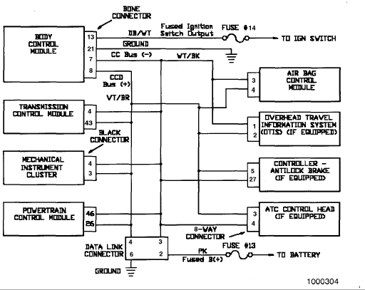
Ok. I have attached the flow of ccd bus info for this car below. Here's what I think that I am dealing with, what do you think?

The airbag light is on all of the time. I at first wanted to blame the clockspring harness since dodge is famous for those going bad at the drop of a dime. What has dawned on me in looking at this diagram is that the ccd bus +/- run their course through the airbag control module, as well as to the cluster. Since I am not able to get codes via the ignition switch on / off trick, and since the airbag light is on I wonder if the correlation could be here.

If the BCM was not operational I would not have power accessories, if the PCM was down on power Id have a no start, if the ATCM was down there'd be no transmisson communication, this car does not have ABS nor OTIS, and the only thing left is ATC Control head which I have to check out as well (although the heat is working, and the A/C still has not been re-charged.)

Would this be a possible culprit? If I get in there and I see that there is voltage in those ccd wires would that indicate that the Airbag module is shot? I dont get ANYTHING from those CCD wires at the cluster, so would a disruption at the ABS module cause such a problem?
Was this
answer
helpful?
Yes
No
+1
Wednesday, January 25th, 2012 AT 2:23 AM
Tiny
CARADIODOC
  • MECHANIC
  • 33,737 POSTS
The buss is working but it sounds to me like there's a break in one of the wires going to the cluster. That would explain why the Check Engine light won't flash any codes. The best approach is to connect a scanner to see what's going on. It also requires a working buss to communicate with the modules. You likely aren't going to get any response from the cluster.

You're going to need a different connector to plug the scanner into the Air Bag module. If it really has a broken clock spring, you'll get a code related to "open squib" or "open initiator". If you get "no response", I'd suspect a corroded splice in a buss wire going to both the cluster and Air Bag module.
Was this
answer
helpful?
Yes
No
Wednesday, January 25th, 2012 AT 2:25 PM
Tiny
JAULT01
  • MEMBER
  • 51 POSTS
I follow what you are saying. So here is a question: Since I am not able to afford to take this car for a scan would it be feasable to test for voltage at the busses for the airbag module, and everwhere else for that matter in order to see where the flow is "breaking?" This way I might be able to search for breaks at twisted pairs / soldiers? If they should read around 6v and do not this would give me a good idea of where in the trough to do some really in depth investigation, right?
Was this
answer
helpful?
Yes
No
Thursday, January 26th, 2012 AT 4:26 AM
Tiny
CARADIODOC
  • MECHANIC
  • 33,737 POSTS
That sounds feasible. I never actually did that myself because I always had access to a scanner. You might check at some local auto parts stores that rent or borrow tools to see if they have one. You don't want a simple code reader. A full scanner is bidirectional meaning you can use it to command the computers to do things and perform self tests. They provide so much information that no mechanic would ever want to be without one.
Was this
answer
helpful?
Yes
No
Thursday, January 26th, 2012 AT 7:02 AM
Tiny
JAULT01
  • MEMBER
  • 51 POSTS
I just went back through everything in the car. I re-checked grounds, ccd bus wires, and even went as far as to yank the hvac outta there to make sure that there was nothing pinched behind it.

I went on a whim, maybe this has narrowed me down to the answer?

As I re-assembled I tested the Airbag module CCD(+) and CCD(-) pins simultaneuously for resistance. The meter read in the green, just as it would just touching the probes together. No resistance means good flow, yes?

I went on to using this same practice at the BCM. The resistance there was horrible on the 5x scale, and read in the (?)Region on the scale above it telling me that there must be something wrong with the flow of voltage through that module.

Is this a reliable means of checking the module? It was a totally different measurement than the Airbag module.

I know that if I were to replace the BCM that I would have to be certain as to the history of the car from which it came. The one problem that I have is that the module on this car, well, the label is faded to the point in which I cant read a thing. Could I find a match using the VIN?

I appreciate all of the help. I have learned an awful lot through this experience!
Was this
answer
helpful?
Yes
No
Friday, February 3rd, 2012 AT 6:18 AM
Tiny
CARADIODOC
  • MECHANIC
  • 33,737 POSTS
A couple of things are confusing me. It sounds like you're using a pointer-type meter. It also sounds like you found continuity between the two buss wires at one computer but not at another one. That doesn't make sense. The same pair of wires goes to every computer so you should read the same thing at any of them. I never measured those wires but it would seem they should not have continuity because that would mean they're shorted together. If they're reading differently at a different place, the logical conclusion is they're pinched together someplace and cut someplace between the pinch and the computers where they read open.

I think what I would do is unplug all the computers in the area, then recheck between the two buss wires at the connectors. They should not read continuity between them, but each wire should have continuity between the various connectors. Check for continuity between each wire and ground too. If one is grounded, that will kill the six volts that shows up on them from the Body Computer. Both wires should have six volts, then when computer signals are broadcast between the computers, the voltage rises about 0.2 volts on one wire and goes down about 0.2 volts at the same time on the other one. If the two wires are shorted together, those signals won't appear and the computers can't share information back and forth.
Was this
answer
helpful?
Yes
No
Friday, February 3rd, 2012 AT 7:10 AM
Tiny
JAULT01
  • MEMBER
  • 51 POSTS
Sorry, man. I know that had to sound a bit confusing. What I meant is basically exactly what you said. I tested from harness to harness on the bus wires and had great continuity. I triple checked ALL ground wires as shown to be in those harness connections as well as body grounds etc.

At the BCM there was resistance, nothing shorted together as you stated.

At the Airbag module the pin connectors for the bus read FULL continuity which would mean that there is an "open" circut or a short, yes?

I also know that the Airbag light is on, so this leads me to replacement of the airbag module. Logical?

One final question, sir. There is nothing to take into consideration other than the DUAL airbag system when swapping modules right?

Thank you once again!
Was this
answer
helpful?
Yes
No
Friday, February 3rd, 2012 AT 8:35 PM
Tiny
CARADIODOC
  • MECHANIC
  • 33,737 POSTS
I think you're getting sidetracked with your readings. If you have continuity, as in 0 ohms, at the air bag module, check again with the module unplugged. You should find the same reading between the two buss wires at any computer. You're reading the same pair of wires, just in different places on the car.

To double-check, the wires should be white / black and violet / brown at every module. To not overlook something silly, there is a blue rectangular 6-pin scanner connector to the right of the steering column. Be sure nothing got plugged into that by mistake. The buss wires go to that too so the scanner can communicate with the various modules.

If you find 0 ohms between the two buss wires at any computer connector, follow them back to see where they're shorted together. As for your air bag and other computers, I doubt one got damaged from working in the dash. From what you've described, it really sounds like you have a cut and pinched wire. Look very closely at the pins in the computers and connectors to see if one got bent over and is touching another one. If you think the air bag module is shorted, just unplug it. If that removes the short, the buss will come back up after cycling the ignition switch off and back on, then the engine should start.
Was this
answer
helpful?
Yes
No
Saturday, February 4th, 2012 AT 1:52 AM
Tiny
JAULT01
  • MEMBER
  • 51 POSTS
I often wondered about that blue harness, I will double check it. It seemed like there was another harness the same size that had only three wires.

As for the readings: I meant that I tested the resistance on the modules themselves. The airbags ccd pins were wide open, showing open flow. The bcm shows resistance.

I did, infact test through each ccd wire and the all checked out.

This is why I questioned the airbag module. I will unplug it to see what happens.
Was this
answer
helpful?
Yes
No
Saturday, February 4th, 2012 AT 8:42 PM
Tiny
RIVERMIKERAT
  • MECHANIC
  • 6,110 POSTS
Ok, let us know what you find out.
Was this
answer
helpful?
Yes
No
Monday, February 6th, 2012 AT 6:24 AM

Please login or register to post a reply.

Sponsored links