Might want to adjust the valve clearances:
VALVE CLEARANCE ADJUSTMENT
NOTE:Adjust valve clearance with engine cold.
Disconnect electrical connector from throttle position sensor. Release fuel pressure. See FUEL PRESSURE RELEASE under REMOVAL & INSTALLATION. Disconnect vacuum hoses and fuel line at fuel pressure regulator.
Disconnect PCV hose. Drain cooling system. Disconnect necessary coolant hoses, electrical connections and vacuum hoses for removal of air intake chamber located above valve cover. See Fig. 9 .
Remove union bolt and gaskets at cold start injector. Power steering pump bracket may need to be removed for access to valve cover. If necessary, remove power steering pump with hoses attached and secure aside. Remove power steering pump bracket.
Disconnect hose from PAIR valve. See Fig. 9 . Remove engine hanger and support for air intake chamber. Remove EGR valve assembly. Remove bolts/nuts, air intake chamber and gasket. Disconnect electrical connectors for removal of wiring assembly, located across engine, in front of valve cover. Remove bolts and wiring assembly.
Remove spark plugs, valve covers and gaskets. Rotate crankshaft clockwise so cylinder No. 1 is at TDC on compression stroke. Cylinder No. 1 is front cylinder on right side when viewed from rear of engine. Ensure timing mark on crankshaft pulley aligns with "0" mark on timing belt cover.
Ensure valve lifters on cylinder No. 1 are loose and valve lifters on cylinder No. 4 are tight. If conditions are not as described, rotate crankshaft clockwise one complete revolution.
Using feeler gauge, measure and record valve clearance between valve lifter and camshaft on exhaust valve of cylinder No. 2 and intake valve of cylinder No. 6. See Fig. 1 .
Fig. 1: Identifying Cylinder Numbers & Valve Locations
Courtesy of TOYOTA MOTOR SALES, U.S.A., INC.
Rotate crankshaft clockwise an additional 120 degrees (1/3 revolution). Measure and record valve clearance on exhaust valve of cylinder No. 3 and intake valve of cylinder No. 1.
Rotate crankshaft clockwise an additional 120 degrees (1/3 revolution). Measure and record valve clearance on exhaust valve of cylinder No. 4 and intake valve of cylinder No. 2.
Rotate crankshaft clockwise an additional 120 degrees (1/3 revolution). Measure and record valve clearance on exhaust valve of cylinder No. 5 and intake valve of cylinder No. 3.
Rotate crankshaft clockwise an additional 120 degrees (1/3 revolution). Measure and record valve clearance on exhaust valve of cylinder No. 6 and intake valve of cylinder No. 4.
Rotate crankshaft clockwise an additional 120 degrees (1/3 revolution). Measure and record valve clearance on exhaust valve of cylinder No. 1 and intake valve of cylinder No. 5. Ensure valve clearance is within specification. See VALVE CLEARANCE SPECIFICATIONS table.
VALVE CLEARANCE SPECIFICATIONS (1)
ApplicationIn. (mm)
Exhaust Valve.009-.013 (.22-.32)
Intake Valve.007-.011 (.18-.28)
(1)Adjust valve clearance with engine cold.
If valve clearance requires adjustment, rotate camshaft so lobe on valve to be adjusted is facing upward, away from valve lifter. Position notch area on valve lifter toward spark plug side of cylinder head. Valve Clearance Adjuster (SST 09248-55040) is used to remove adjusting shim.
Using SST "A" of valve clearance adjuster, push downward on valve lifter. Place SST "B" between camshaft and valve lifter. Remove SST "A". See Fig. 2 .
Fig. 2: Adjusting Valve Clearance
Courtesy of TOYOTA MOTOR SALES, U.S.A., INC.
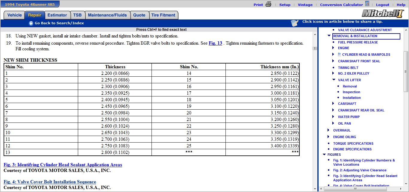
Using small screwdriver and magnet, remove adjusting shim. Measure thickness of removed adjusting shim. Using measured valve clearance and adjusting shim thickness, select proper replacement adjusting shim. See Fig. 5 -8.
Install replacement adjusting shim. Recheck valve clearance. Install NEW gasket on valve cover. Apply sealant at indicated areas on cylinder head. See Fig. 3 .
Install gasket and valve cover. Install and tighten valve cover bolts to specification in sequence using several steps. See Fig. 4 . See TORQUE SPECIFICATIONS .
Using NEW gasket, install air intake chamber. Install and tighten bolts/nuts to specification.
To install remaining components, reverse removal procedure. Tighten EGR valve bolts to specification. See Fig. 13 . Tighten remaining fasteners to specification. Fill cooling system.
Mar 26, 2012 at 6:10 AM