Apr 15, 2011 at 4:19 AM
engine miss
1994 OLDSMOBILE DELTA 88
Repair Safety Notice:
This information is for general instructional purposes only. Vehicle repair can be dangerous.
Verify all information, follow manufacturer service procedures, use proper tools and safety equipment,
and consult a qualified repair shop when needed.
Advertisement
On the gm vechiles when you unplug the coolant temp sensor or have a open in that circuit the cooling fan will come on.Because when that happens the computer reads that as the coldest reading it can which is -40 degrees then computer turns the fan on to protect the engine from overheating.You most likely have a bad sensor or bad connector connection or wiring.If you had a scan tool that could read live engine data it would be easy to find the problem.So i think your right your best bet would be to take it to a shop.Let me know what you find.
Advertisement
Which of the two sensors are you referring to regarding the effects of an open circuit? Remember that when we did use the scan tool on a live engine it said the temperature was over 300 degrees when it was not.
Apr 15, 2011 at 1:52 PM
Iam referring to the coolant temp one with the black wire and the yellow wire going to it.If it reads over 300 fan runs all the time and you could have a bad sensor or those two wires are shorted together.So you would watch the temp on the scanner screen when you unplugged it if it drops down when unplugging to like -40 then bad sensor.
Apr 15, 2011 at 4:32 PM
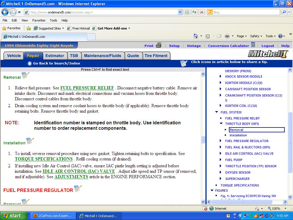
Hello saturntech9. It's been determined that my temp sensor under the throttle body is definitely bad. I'm having trouble loosening the throttle body so I can get to the sensor and replace it. I've removed two hex nuts that seem to be the only fasteners holding the throttle body but the body wont budge. It's aluminum and I'm afraid of cracking it with more force. Any suggestions?
May 5, 2011 at 2:24 PM
Is the 8th digit of your vin a L or a 1?
May 5, 2011 at 4:56 PM
It is an L
May 5, 2011 at 6:14 PM
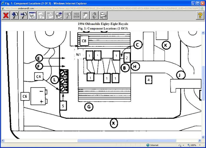
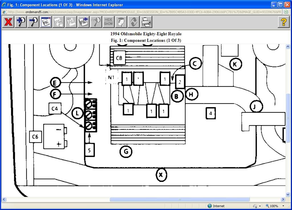
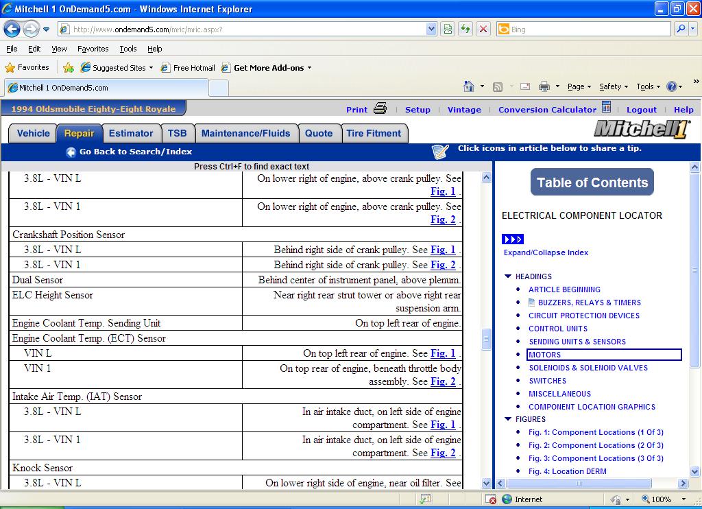
With the L vin it should be on the top left rear of engine according to my info.The vin 1 says its under the throttle body.In the diagram i posted the sensor is labeled C.
Images (Click to enlarge)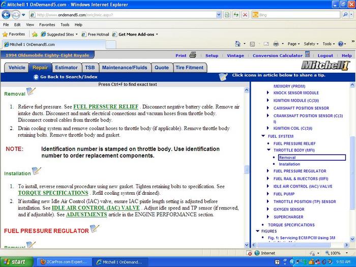

May 5, 2011 at 7:52 PM
It is under the throttle body - I can reach it with my fingertips and the wire color codes are correct. Throttle body is on the driver side of the engine and both temp senders are on that side.
I'm thinking the throttle body will need to be moved somewhat for this one.
I'm thinking the throttle body will need to be moved somewhat for this one.
May 5, 2011 at 8:47 PM
Does it matter that the sensor you show at location C is the one with a single green wire and not with yellow and black ?
May 6, 2011 at 3:03 AM
Yes it matters you want the one with the two wires the black wire and the yellow wire.If you can reach it with your finger tips you should be able to get it without removing the throttle body.I would drain some coolant down get a 1/4" drive ratchet and socket and possibly a short extension remove it and then start the new sensor threading it by hand.I would at least try to remove it without removing the throttle body.
May 6, 2011 at 4:16 PM
The bad news is that I cannot get fingers far enough to remove the
plug from the top of the sensor.
The good news is that I finally found other nuts holding down the throttle body. I removed the linkage, drained some coolant, and removed the body - finally !!
Replaced the sensor (with black and yellow wires) and the throttle body gasket, thoroughly cleaned the throttle body and put everything back together. No check engine light ! Car runs great,
noticebly smoother at idle and under acceleration at highway speeds.
Now that the ECM is getting good data I'm expecting the mileage to be back up to normal as well. Thanks again for all your help. We finally got it! PS - I've sent 3 of my friends to your website.
Mike
May 6, 2011 at 8:57 PM
Glad to hear you got it all figured out and up and running good again.Hit me up if you have anymore issue's.Glad to hear your spreading the good word to your friends about our website keep it up.
May 6, 2011 at 10:58 PM