The heater-ventilation system is a blend air design and consists of the following major components: the heater blower assembly, the plenum, air distribution ducts and registers, control assembly, control cable, the defroster nozzle and side window demisters.
The heater blower assembly is located in the engine compartment and contains the blower motor and wheel, blower resistor and, outside air shutoff door.
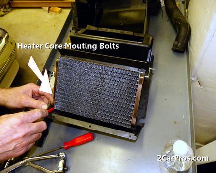
The plenum is located in the passenger compartment and contains the heat-defrost door, temperature blend door, vent-heat door and the heater core. The defroster nozzle is a five-outlet nozzle and connects to the defroster outlet in the plenum.
The control assembly, located in the instrument panel is shown in the following illustration.
The heater-ventilation system receives outside air from the cowl top grille for system operation. Outside air enters the blower from the cowl air intake and is forced through and/or around the heater core in the plenum. Air is then directed to the panel registers, floor outlets, demisters, and defroster outlets depending on the setting of the Function Control **** (refer to Air Distribution). The system is controlled by one manually adjusted cable, and one vacuum controlled ****. The cable is located between the control assembly, located in the instrument panel, and a cam on the plenum assembly. The vacuum harness is located between the control assembly and vacuum motors on the plenum assembly. The function **** operates the Heat-Defrost door and Vent-Heat door located in the plenum by means of a vacuum harness. The temperature control **** operates the temperature blend door in the plenum. Air flow volume is controlled by a blower switch and a resistor assembly to provide four blower operating speeds. The function **** has an OFF position which actuates the outside air door to CLOSED position and shuts off the blower motor.
Outside air is drawn into the blower housing through an opening located under the cowl top grille by the blower motor and wheel assembly. From there, the blower wheel forces the outside air into the plenum and through and/or around the heater core. The heated and unheated air (except when the Temperature Control **** is in fully COOL or WARM) then blends together in the plenum for distribution to the floor outlets, instrument panel registers or defroster outlets. When the temperature control **** is at fully COOL or WARM, all outside air bypasses or passes through the heater core and no blending of air occurs.
Monday, December 13th, 2010 AT 11:22 PM


