I have no spark after doing head job and want to know how to troubleshoot especially CAM and Crank Sensors.

Tiny
GMANCARZ
  • MEMBER
  • 1991 SUBARU LEGACY
  • 230,000 MILES
Hello. I "drove" into my garage a 1991 Subi Legacy 2.2L 2wd for a head job that went flawless, except now I have no spark coming from the coil pack. The only spark related items I disconnected was the battery, 3 harness plugs coming from the fuse box, and the Cam Sensor at the back of the left cam, (did not disco it's connector). I triple checked all wiring connections just in case one came loose while moving the intake up and back, out of the way to do the job. Checked all fuses too.

Can't see why either a cam or crank sensor would have suddenly gone bad, but know I'll get a no spark problem if either one did, sooo.

How do I check those sensors? I only have a test light and a standard Sunpro multi-meter. Any other ideas are welcome.

Thanks,

Gman
Saturday, October 1st, 2011 AT 10:30 PM
6 Replies

Tiny
JACOBANDNICKOLAS
  • MECHANIC
  • 108,128 POSTS
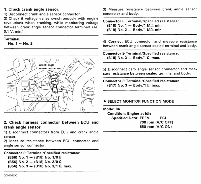
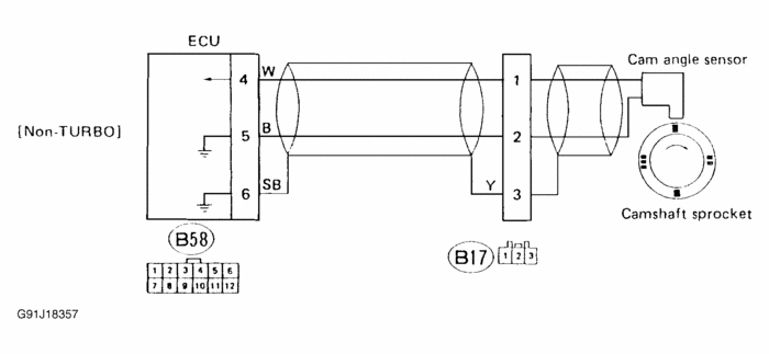
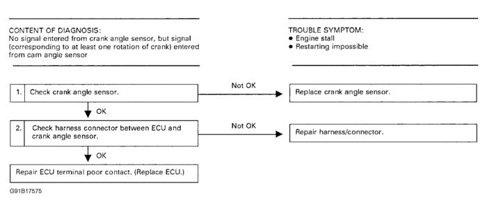
That is a good question. It happens. What to do is start by checking continunity between the crank sensor and the ECU. After that, review the attached picturers. There is a flow chart, schematic. Let me know what you find.
Was this
answer
helpful?
Yes
No
Saturday, October 1st, 2011 AT 11:06 PM
Tiny
GMANCARZ
  • MEMBER
  • 4 POSTS
Thanks for the good start, but I still have a couple questions;

1) What does it mean when they say measure resistance between cam or crank sensor “sealed terminal and body”?

2) On diagram G91J18357 what are the readings supposed to be at the connector between the sensor and the ecu, how do you check them and are those checks with the connector disconnected or connected and back-probed?
Was this
answer
helpful?
Yes
No
Saturday, October 1st, 2011 AT 11:56 PM
Tiny
JACOBANDNICKOLAS
  • MECHANIC
  • 108,128 POSTS
They should be disconnected. You are checking resistance in the wiring.
Was this
answer
helpful?
Yes
No
Sunday, October 2nd, 2011 AT 12:25 AM
Tiny
GMANCARZ
  • MEMBER
  • 4 POSTS
You did not answer my question #1. Question So are you saying I'm measuring resistance in the wires coming from either the crank or cam sensors and that the resistance should be @
Was this
answer
helpful?
Yes
No
Sunday, October 2nd, 2011 AT 1:18 AM
Tiny
GMANCARZ
  • MEMBER
  • 4 POSTS
You did not answer my question #1. Please explain.
So are you saying I'm measuring resistance in the wires coming from either the crank or cam sensors at the terminals, (from each wire to body/ground) and that the resistance should be @ 1M ohm for the crank sensor and 1 ohm for the cam sensor, and if it is that this shows the sensor is functional? The cam sensor has 3 wires; which one gets tested? One? All? And is this with the motor cranking over?
There must be some kind of readable pulse for each sensor, yes, which proves they are functioning.
Please be more detailed.
Was this
answer
helpful?
Yes
No
Sunday, October 2nd, 2011 AT 1:19 AM
Tiny
JACOBANDNICKOLAS
  • MECHANIC
  • 108,128 POSTS
I'm sorry. I just found something quicker and easier. First, check for power to the cam sensor (black and white wire) should have a minimum of 1 volt with the ignition on. According to mitchel, the same for the crank sensor (black and white wire too. Check that and let me know what you find. NOTE: If you crank the engine, the voltage should vary with each engine revolution.

We will check resistance when we determine if there is power to the sensors. Again, I'm sorry I missed that part of the question.
Was this
answer
helpful?
Yes
No
Sunday, October 2nd, 2011 AT 3:48 AM

Please login or register to post a reply.

Sponsored links