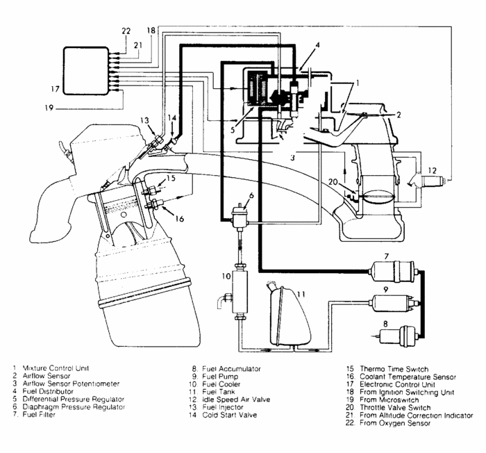
You'll need a fuel pressure gauge. You can usually borrow one from a large auto parts chain store.
FUEL DELIVERY & SYSTEM PRESSURES
System Pressure
Connect Pressure Gauge (VW 1318) between line from fuel distributor to cold start valve and
test port connection on lower chamber of fuel distributor, using Adapter Fittings (VW 1318/5).
Test port is sealed by a threaded plug. Bridge fuel pump relay with Jumper Switch (US 4480/3).
1.
Disconnect wiring from Differential Pressure Regulator (DPR). Open valve on pressure gauge
(points at cold start valve line when open) and activate fuel pump. System pressure must be 75-
82 psi (5.3-5.8 kg/cm2 ). If pressure reading is low and fuel pump delivery quantity is good,
replace pressure regulator.
2.
If pressure reading is high, disconnect fuel tank return line from DPR. Repeat test. If reading is
correct, check for plugged return line. If reading is incorrect with line open, replace DPR.
3.
Differential Control Pressure
Close valve on pressure gauge. Activate fuel pump with jumper switch. Leave DPR
disconnected. DPR reading should be 2.9-7.0 psi (.2-.5 kg/cm2 ) less than system pressure. If
pressure is incorrect, disconnect lower chamber return line and measure volume.
1.
Close open port to diaphragm pressure regulator. Activate fuel pump with jumper switch. Fuel
volume should be.14-.16 qts. (.13-.15L) for period of one minute. If volume is correct, replace
DPR. If volume is incorrect, replace fuel distributor.
2.
Close valve on pressure gauge. Install Test Harness (1315A/1) between DPR and vehicle
harness. Set multimeter to DCA 200 mA scale. Connect multimeter to test harness. Disconnect
wiring to coolant temperature sensor. Connect 15 k/ohm side of Test Resistor (VW 1490) to
sensor wiring.
3.
Turn on ignition and fuel pump. Differential pressure should be 10-17.5 psi (.7-1.2 kg/cm2 )
less than system pressure. DPR current should be 50-80 mA. If pressure is incorrect and current
is correct, replace DPR.
4.
If both pressure and current readings are incorrect, remove test harness from DPR. Ensure
resistance of DPR is 17.5-21.5 ohms. If reading is incorrect, replace DPR.
5.
If reading is correct, check ground from temperature sensor to cold start valve. If ground is
good, check power supply fuse. If fuse is okay, check terminals on ECU connector. If connector
is okay, replace ECU.
6.
Residual Pressure & Internal Leak Testing
Open valve on pressure gauge. Operate fuel pump for 30 seconds. Pressure can drop to a
minimum of 38 psi (2.7 kg/cm2 ) after 10 minutes. If pressure drops below specification, inspect
fuel pump check valve and all fuel fittings for leakage.
1.
NOTE: Pressure and leak testing does not include checking cold start
valve.
FUEL INJECTION SYSTEM - BOSCH CIS-E -1988 Volkswagen Jetta Page 1 of 3
11/25/2011
If there are no leaks, check airflow sensor plate clearance. If plate clearance is correct, replace
diaphragm pressure regulator and repeat leak test. If pressure drop is not within specification,
replace fuel distributor "O" rings.
2.
Transfer Pump Delivery Volume
Check voltage supply to pumps. Connect Jumper Switch (US 4480/3) in place of fuel pump
relay, on relay panel. Remove fuel filler cap. Disconnect and plug off Black fuel line from
sending unit.
1.
Connect hose to sender port and place in measuring container. Turn on fuel pumps. Minimum
transfer pump delivery volume should be.42 qts. (.4L) in 10 seconds. Reconnect fuel line to
sender.
2.
Main Pump Delivery Volume
Check transfer pump (if equipped) and fuel filter. Disconnect fuel return line and place in
measuring container. Switch on fuel pump with jumper switch. Check fuel pump delivery
volume for 30 second period. Delivery rates are given with voltage reading at pump as volume
will change with different voltages.
1.
Minimum delivery volume for Fox, Quantum and Quantum Syncro models is.71 qts. (.68L) for
30 seconds with reading of 11.4 volts at fuel pump. Minimum delivery volume for other models
is.62 qts. (.59L) with 11.4 volts at fuel pump.
2.
Fuel Distributor
Check sensor plate adjusting lever and fuel distributor control piston for smooth operation.
Disconnect fuel injector lines at fuel injectors.
1.
Remove fuel pump relay and bridge fuel pump circuit. Use Jumper Switch (US 4480/3) in place
of fuel pump relay. When pressure has built up, turn off fuel pump. Move sensor plate from rest
position to end of travel.
2.
Uniform resistance should be felt during entire movement. No resistance should be felt on
quick return to rest position. Connect injector lines. Install fuel pump relay.
3.
Injector Quantity Comparison
Remove fuel pump relay, from relay panel, and install Jumper Switch (US 4480/3) in off
position in place of relay. Attach Fuel Quantity Analyzer (US 4480) to bumper and secure in
place. Remove injectors from cylinder head with fuel lines attached. Check and replace fuel
injector "O" rings as necessary.
1.
Check tightness of injector insert (2-piece inserts). If inserts are loose, remove and clean
threads. Use sealing compound when installing upper insert. Replace sealing washer that goes
against cylinder head below lower portion of insert. Lubricate injector "O" rings with gasoline
and install injectors, with fuel lines connected, into fuel quantity analyzer tubes.
2.
Ensure lines are not kinked or bent. Loosen fittings to align fuel lines and retighten. Remove
rubber boot from airflow sensor housing above sensor plate. Turn and lift setting screw and
adjusting slide of Sensor Plate Adjustable Holder (VW 1348/1) into upper position. This
simulates full throttle operation. See Fig. 11.
3.
FUEL INJECTION SYSTEM - BOSCH CIS-E -1988 Volkswagen Jetta Page 2 of 3
11/25/2011
Fig. 11: Sensor Plate Adjustable Holder (VW 1348/1)
Courtesy of AUDI OF AMERICA, INC.
Place sensor plate adjustable holder on airflow sensor housing with holder centered over plate.
Pointer on edge of holder base must point toward center of fuel distributor. Push adjusting slide
of holder down onto stop.
4.
Turn adjusting screw clockwise until magnetic end touches sensor plate retaining bolt. Activate
fuel pump with jumper switch. Turn adjusting screw of holder counterclockwise until any one
injector starts to deliver fuel. Turn off jumper switch and empty fuel quantity analyzer after
taking sample.
5.
Idle injection quantity is measured first. Lifting adjusting slide of holder to first stop simulates
idle position of sensor plate. Activate fuel pump until fuel level reaches 20 ml on scale of any
tube.
6.
Check that all injectors have identical spray patterns that are even and cone-shaped. If not, raise
sensor plate up quickly to full lift position and release. Repeat idle quantity test. Compare
amounts of fuel delivered by all injectors with analyzer held level. Maximum difference in
delivery quantity between injectors is 3.0 ml of fuel.
7.
If fuel delivery quantity differs between high and low levels by more than 3.0 ml, interchange
injectors and repeat test. If difference of delivery quantity changes with injectors, replace
injectors. If difference of delivery quantity does not change with movement of injectors, either
fuel lines are pinched or fuel distributor is defective.
8.
Measure full throttle injection quantity. Empty analyzer into fuel tank and reinstall injectors in
analyzer. Lift adjusting slide of holder to last stop to simulate full throttle position of sensor
plate. Activate fuel pump with jumper switch until fuel level reaches 80 ml on scale of any tube
of analyzer.
9.
Check that all injectors have identical spray patterns that are even and cone-shaped. If not, raise
sensor plate up quickly to full lift position and release. Repeat full throttle quantity test.
Compare amounts of fuel delivered by all injectors with analyzer held level. Maximum
difference in delivery quantity between injectors is 8.0 ml of fuel.
10.
If fuel delivery quantity differs between high and low levels by more than 8.0 ml, interchange
injectors and repeat test. If difference of delivery quantity changes with injectors, replace
injectors. If difference of delivery quantity does not change with movement of injectors, either
fuel lines are pinched or fuel distributor is defective.
11.
Check fuel injectors for leakage immediately after delivery quantity test is complete. Set sensor
plate in rest position. Activate fuel pump with jumper switch for 2 minutes. Injectors should not
drip. Replace injectors that drip.
See image. Fuel filter is probably located on the frame between the engine and fuel tank.
Image (Click to make bigger)
Tuesday, December 20th, 2016 AT 11:51 AM


