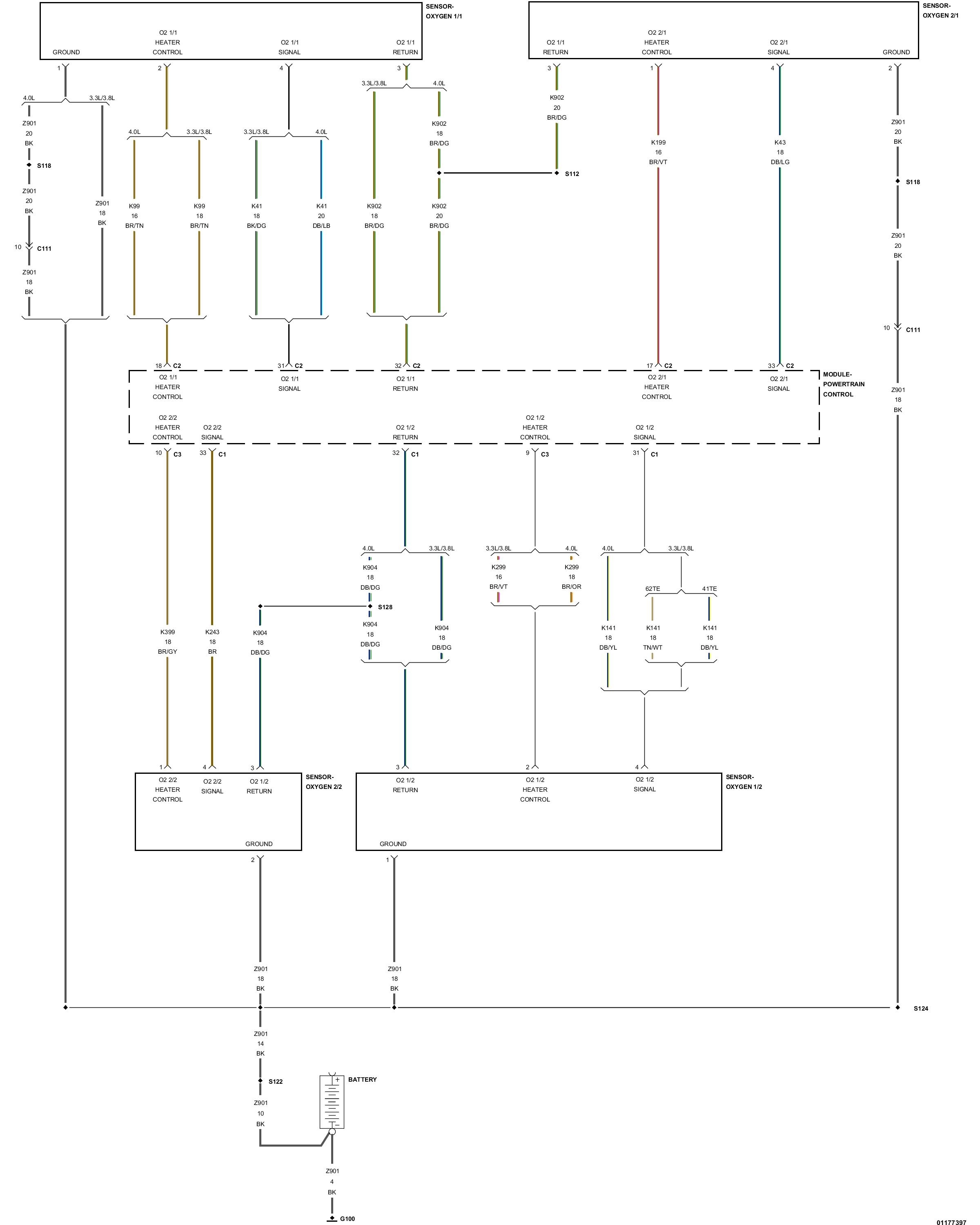
The voltage is supplied through the PCM directly. Both show Black as ground wires that connect at a splice and go to a ground at the transmission.
Sensor B1/1 shows power on a Brown w/Tan trace from PCM Connector 2 Pin 18
Sensor B1/2 shows power on a Brown w/Violet trace from PCM Connector 3 Pin 9
However there is only voltage to the sensors for a very short time normally. Here is the book test for the system. I cropped out a bunch of spaces and the PCM verification testing after every step, that just has you scan and clear any codes you set during testing.
Step 1 - Oxygen Sensor Wiring and Connectors
Turn the ignition off.
Using the wiring diagram/schematic as a guide, inspect the wiring and connectors between the oxygen sensor and the PCM for any damage.
Turn the ignition on.
Monitor the scan tool data relative to the sensor and wiggle test the wiring and connectors.
Look for the data to change or for a DTC to set during the wiggle test.
Were any problems found?
Yes - Repair as necessary.
No - Go to Test Step 2
Step 2 - Oxygen Sensor Voltage
Start the engine and allow it to reach normal operating temperature.
With a scan tool, monitor all O2 sensor voltage readings.
Is the voltage switching between 2.5 and 3.4 volts for all O2 sensors?
Yes - Go to Step 3
No - Go to Step 4
Step 3 - O2 Sensor Heater Operation
Turn the ignition off.
Wait a minimum of 10 minutes to allow the O2 sensor to cool down before continuing the test. Allow the O2 sensor voltage to stabilize at 5.0 volts.
Turn the ignition on.
With a scan tool, actuate the O2 sensor heater.
With the scan tool, monitor O2 sensor voltage for at least 2 minutes.
Does the voltage remain at more than 4.5 volts?
( During this step I would connect a voltmeter or test light to the heater wires mentioned above, either using piercing probes or remove a small part of the insulation to connect. That way you can see if the voltage is actually there. When you are finished testing use liquid electrical tape to seal the connection points you made )
Step 4 - O2 Sensor Test
Turn the ignition off.
Check for contaminants that may cause improper O2 sensor operation, such as contaminated fuel, unapproved silicone, or evidence of oil or coolant.
Disconnect the O2 sensor harness connector.
Turn the ignition on.
With a scan tool, monitor the O2 sensor voltage.
The voltage should be approximately 5.0 volts with the connector disconnected.
Connect a jumper wire between the signal circuit and the return circuit in the O2 sensor harness connector.
The voltage should drop from 5.0 volts to 2.5 volts with the jumper wire in place.
Is the O2 sensor voltage displayed on the scan tool as described?
Yes - Replace the O2 sensor.
No - Go to Step 5
Step 5 - O2 Sensor Signal Circuit
Using the wiring diagram/schematic as a guide, inspect the O2 sensor signal circuit and connectors between the O2 sensor and the PCM for any damage.
Check the O2 sensor signal circuit for a short to ground, open circuit, short to voltage, or high resistance.
Any problems found?
Yes - Repair as necessary.
No - Go to Step 6
Step 6 - O2 Sensor Return Circuit
Using the wiring diagram/schematic as a guide, inspect the O2 sensor return circuit and connectors between the O2 sensor and the PCM.
Check the O2 Sensor return circuit for a short to ground, open circuit, short to voltage or high resistance.
Any problems found?
Yes - Repair as necessary.
No - Go to Step 7
Step 7 - Powertrain Control Module Test
Using the wiring diagram/schematic as a guide, inspect the wiring and connectors for the O2 sensor at the PCM.
Look for any damaged wires or bad connectors.
Monitor the scan tool data relative to the components tested in this procedure and wiggle test the wiring and connectors.
Were any problems found?
Yes - Repair as necessary.
No - Replace and program the PCM.
Images (Click to enlarge)
Aug 15, 2018 at 1:05 PM