A mass air flow sensor can become inaccurate after large amounts of air (high mileage) has passed over the hot wire and must be cleaned before normal operation will return. These sensors are delicate and are prone to failure, fortunately replacement is simple in most cases. Engine performance issues involving this sensor include, hesitation, low power and poor mileage.
Let's Jump In!
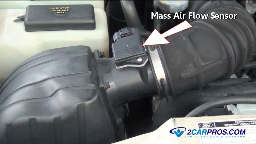
Step 1 - The mass air flow sensor is designed to monitor the volume of air passing into the engine at any giving time (located in the intake tube connected to the throttle body) this information is then transmitted to the computer for calculations while helping adjust fuel injector input and ignition timing settings.
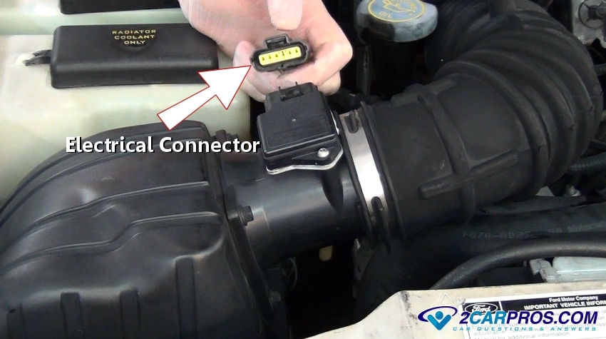
Step 2 - All maf sensors include an electrical connector which is used to transfer data to the computer.
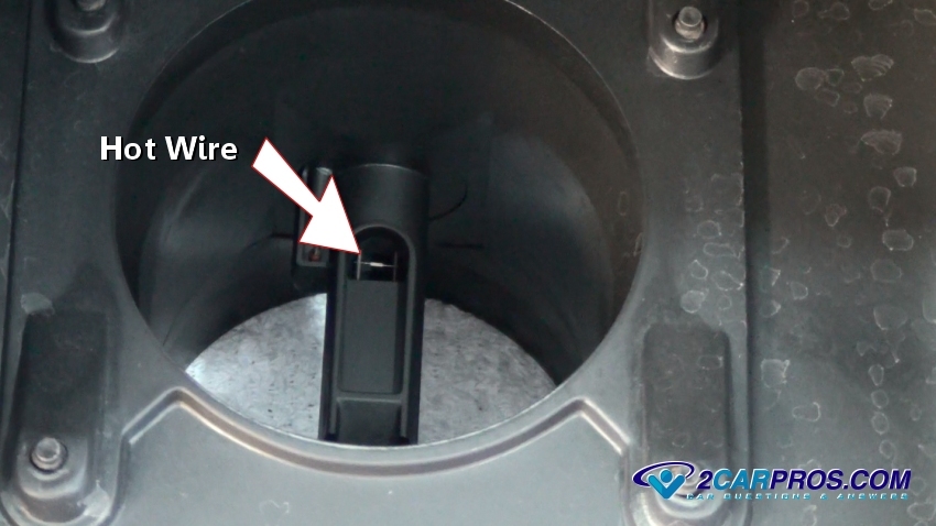
Step 3 - A hot wire is used to detect air flow by measuring the resistance change as varying amounts of air are passed over it.
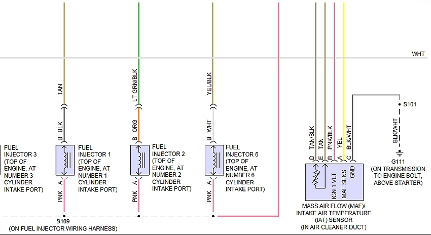
Step 4 - Sensor wiring diagrams are used to help troubleshoot electrical problems.
Questions?
Our certified technicians are ready to answer mass air flow sensor questions for free. We hope you saved money and learned from this guide. We are creating a full set of car repair guides. Please subscribe to our 2CarPros YouTube channel and check back often for new videos which are uploaded regularly.