Hello ... labor time for replacement of the sensor is 1 hour and for the adjustment is 30 minutes... I do not have a price listed for the part. Your local autoparts store or dealer should be able to supply current price .. the price will be a lot less than having the transmission replaced or rebuilt !!
DTC 313/P0705: GEAR POSITION SENSOR SIGNAL INCORRECT
If DTC 313 is set, check gear shift position sensor adjustment. Ensure gear shift is set to "N" position. Remove battery, battery shelf, and air intake manifold. Remove transmission cable from rod arm. Remove selector lever. Install gear position Alignment Tool (999 5475) on control shaft. If shaft is set correctly to "N" position and indentation on alignment tool aligns with mark on gear position sensor, go to step 3). If indentation does not align with mark, go to next step.
Remove dipstick pipe bracket and gear position sensor screws. Rotate gear position sensor so mark on switch aligns with indentation on tool. Tighten sensor screws to 37 ft. lbs. (25 N.m). To complete installation, reverse removal procedure.
Ensure ignition is off. Connect ohmmeter between gear shift position sensor case and transmission housing. If ohmmeter reads about zero ohms, go to next step. If ohmmeter does not read about zero ohms, check gear shift position sensor ground. Repair as necessary.
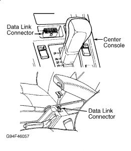
Ensure ignition is off. Connect measuring unit to TCM connector. Check TCM grounds. See WIRING DIAGRAMS . Repair as necessary. If grounds are okay, connect ohmmeter between measuring unit terminal No. 20 and terminals No. 3 ("A"), No. 4 ("B"), No. 5 ("C"), and No. 6 (PA). If ohmmeter reads infinite resistance, go to next step. If ohmmeter does not read infinite resistance, check for short circuit to ground in White, Yellow, Green, and Blue wires between gear position sensor and TCM.
Ensure ignition is off. Disconnect transaxle connector. Connect ohmmeter between transaxle connector terminals and measuring unit terminals. See TRANSAXLE CONNECTOR/MEASURING UNIT TERMINAL RESISTANCE table below. If ohmmeter reads about zero ohms for all readings, go to next step. If ohmmeter does not read about zero ohms for all readings, check for open circuit in wiring between transaxle connector and TCM. Repair as necessary.
TRANSAXLE CONNECTOR/MEASURING UNIT TERMINAL RESISTANCE
Transaxle Connector Terminal.....Measuring Unit Terminal
1 (White wire).............................3
2 (Yellow wire)............................4
3 (Green wire).............................5
4 (Blue wire)................................6
Ensure ignition is off. Disconnect transmission and TCM connectors. Turn ignition on. Connect test light between measuring unit terminal No. 20 and gear position sensor connector terminals No. 1 (White wire), No. 2 (Yellow wire), No. 3 (Green wire), and No. 4 (Blue wire). If test light comes on, check wiring for a short circuit to voltage. If test light does not come on, go to next step.
Ensure ignition is off. Connect TCM and transaxle connectors. Turn ignition on. Using scan tool, go into SCROLLING VALUES. Read gear shift sensor position. Move gear shift position sensor to all shift positions several times. Repeatedly select same position to check operation. If all values are okay, DTC was caused by poor terminal contact. If all values are not okay, replace gear shift position sensor.
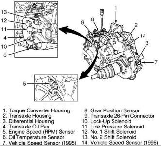
GEAR POSITION SENSOR
NOTE:Gear position sensor may also be referred to as neutral safety switch.
Removal & Installation
Ensure transaxle is in "N" position and parking brake is applied. Remove battery, battery tray and air intake hose. Remove air cleaner assembly. Disconnect transaxle cable from shift rod arm. Remove shift rod arm from sensor. Note position of notch on sensor for installation reference.
Remove nut, washer and seal from sensor. Loosen dipstick bracket. Remove 2 bolts securing sensor to transaxle. Remove sensor from control shaft.
Separate the connector on transaxle. Disassemble connector. Remember rubber gasket. Disconnect cable clamps and detach connector from transaxle. Remove sockets from connector casing. Remove rubber seal from connector.
Insert screwdriver between casing and socket and press catch in. At the same time slide the sockets out of the casing. Detach socket for gear position sensor (8-pin) from other sockets. Remove gear position sensor.
Reassemble position sensor socket with the other sockets. Reinstall sockets in casing and put rubber seal back in place. Reinstall connector on transaxle. Reinstall cable clamps around cable harness and rubber seal. Reinstall upper connector section. Remember rubber gasket.
To install, reverse removal procedure. Ensure notch on sensor is located in exact position as prior to removal. Tighten 2 sensor bolts to 18 ft. lbs (25 N.m). If adjustment is necessary, see GEAR POSITION SENSOR under ADJUSTMENTS in AUTOMATIC TRANSMISSION SERVICING VOLVO article.
Hope this helps .. let me know if you need any more assistance

Mar 18, 2010 at 2:47 AM