Welcome to 2CarPros.
Any time the transmission needs removed, I call it difficult because it's a lot of work. However, you may feel differently. With that in mind, I am going to provide the directions you will need to do it. With that information, you can determine if it is something you want to do. I will start with the clutch assembly which includes the release bearing and testing and inspection. I strongly recommend replacing the pressure plate, clutch disc, and at least resurfacing the flywheel if you take it apart. You don't want to do it a second time and the kits aren't terribly expensive. The second set of directions will relate to removal of the transmission. The third set of directions is putting it all back together. All attached pictures will correlate with these directions.
_________________________________________
CLUTCH UNIT
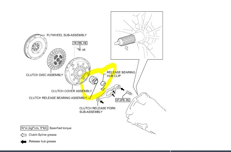
Components
picture 1
REMOVAL
1. REMOVE MANUAL TRANSMISSION UNIT ASSEMBLY
pic 2
2. REMOVE CLUTCH RELEASE FORK SUB-ASSEMBLY
a. Remove the clutch release fork together with the clutch release bearing from the transmission assembly.
3. REMOVE CLUTCH RELEASE BEARING ASSEMBLY
a. Remove the clutch release bearing assembly from the clutch release fork.
4. REMOVE RELEASE FORK SUPPORT
a. Remove the release fork support from the transaxle assembly.
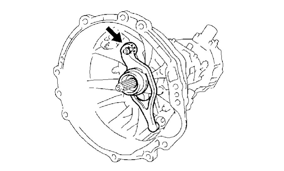
5. REMOVE RELEASE BEARING HUB CLIP
pic 3
6. REMOVE CLUTCH COVER ASSEMBLY
a. Align the matchmark on the clutch cover assembly with the one on the flywheel sub-assembly
b. Loosen each set bolt one turn at a time until the spring tension is released.
C. Remove the 6 bolts and clutch cover assembly
NOTICE: Do not drop the clutch disc assembly.
7. REMOVE CLUTCH DISC ASSEMBLY
NOTICE: Keep the lining part of the clutch disc assembly, pressure plate and surface of the flywheel sub-assembly free from oil and foreign matter.
INSPECTION
pic 4
1. INSPECT CLUTCH DISC ASSEMBLY
a. Using vernier calipers, measure the rivet head depth.
Maximum rivet depth: 0.3 mm (0.012 inch)
If necessary, replace the clutch disc assembly
b. Install the clutch disc assembly onto the transaxle assembly.
NOTICE: Take care not to insert the clutch disc assembly in the wrong orientation.
Pic 5
c. Using a dial indicator, check the clutch disc assembly runout.
Minimum runout: 1.0 mm (0.039 inch)
If necessary, replace the clutch disc assembly
pic 6
2. INSPECT CLUTCH COVER ASSEMBLY
a. Using vernier calipers, inspect the depth and width of wear of the diaphragm spring.
Minimum:
A (Depth): 0.5 mm (0.020 inch)
B (Width): 6.0 mm (0.236 inch)
If necessary, replace the clutch cover assembly.
Pic 7
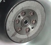
3. INSPECT FLYWHEEL SUB-ASSEMBLY
a. Using a dial indicator, inspect the flywheel sub assembly runout.
Maximum runout: 0.1 mm (0.004 inch)
If necessary, replace the flywheel sub-assembly.
Pic 8
4. INSPECT CLUTCH RELEASE BEARING ASSEMBLY
a. Turn the release bearing by hand while applying force in the axial direction.
HINT: The bearing is permanently lubricated and requires no cleaning or lubrication.
If necessary, replace the release bearing assembly.
INSTALLATION
pic 9
1. INSTALL CLUTCH DISC ASSEMBLY
a. Insert SST into the clutch disc assembly, then insert them into the flywheel sub-assembly
SST 09301-00220
NOTICE: Take care not to insert the clutch disc assembly in the wrong orientation.
Pic 10
2. INSTALL CLUTCH COVER ASSEMBLY
a. Align the matchmarks on the clutch cover assembly and flywheel sub-assembly.
B. Following the procedures shown in the illustration, tighten the 6 bolts, in the order starting with the bolt located near the knock pin on the top.
Torque: 19 Nm (195 kgf-cm, 14 ft. Lbs.)
HINT: Following the order in the illustration, uniformly tighten the bolts.
C. Move SST up and down, right and left lightly, after checking that the disc is in the center, and tighten the bolts.
Pic 11
3. INSPECT AND ADJUST CLUTCH COVER ASSEMBLY
a. Using a dial indicator with roller instrument, check the diaphragm spring tip alignment.
Maximum non-alignment: 0.5 mm (0.020 inch)
If the alignment is not as specified, adjust the diaphragm spring tip alignment using SST.
SST 09333-00013
4. INSTALL RELEASE FORK SUPPORT
a. Install the release fork support onto the transaxle assembly.
Torque: 47 Nm (479 kgf-cm, 35 ft. Lbs.)
5. INSTALL RELEASE BEARING HUB CLIP
pic 12
6. INSTALL CLUTCH RELEASE FORK SUB-ASSEMBLY
a. Apply release hub grease to the release fork and release the bearing assembly contact surfaces, release fork and push rod contact surface and release fork pivot point.
Sealant: Part No. 08887-01806, RELEASE HUB GREASE or equivalent
b. Install the release fork onto the release bearing assembly.
7. INSTALL CLUTCH RELEASE BEARING ASSEMBLY
a. Apply clutch spline grease to the input shaft spline.
Sealant: Part No. 08887-01706, CLUTCH SPLINE GREASE or equivalent
b. Install the bearing onto the release fork, and then install them onto the transaxle assembly.
NOTICE: After installation, move the fork forward and backward to check that the release bearing slides smoothly.
8. INSTALL MANUAL TRANSMISSION UNIT ASSEMBLY
___________________________________
Transmission removal
TRANSMISSION REMOVAL
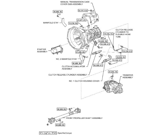
MANUAL TRANSMISSION ASSEMBLY
Components
pic 13
Components
pic 14
Components
pic 15
REMOVAL
1. DISCONNECT CABLE FROM NEGATIVE BATTERY TERMINAL
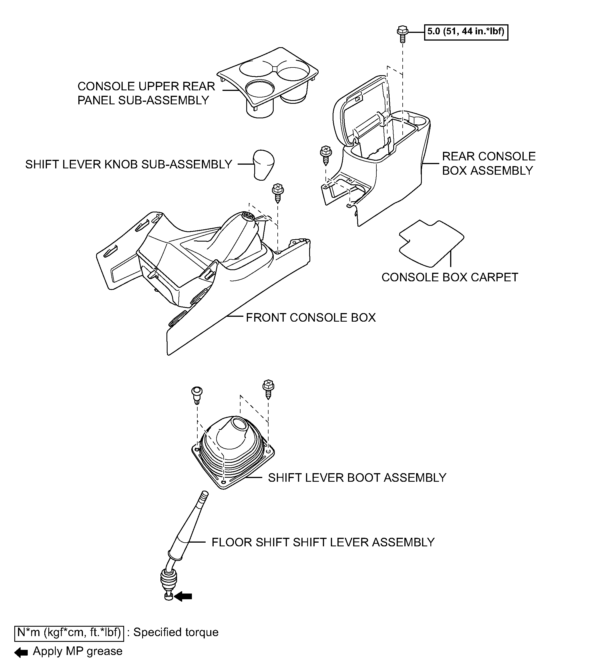
2. REMOVE CONSOLE UPPER REAR PANEL SUB-ASSEMBLY
3. REMOVE REAR CONSOLE BOX ASSEMBLY
4. REMOVE SHIFT LEVER KNOB SUB-ASSEMBLY
5. REMOVE FRONT CONSOLE BOX
pic 16
6. REMOVE SHIFT LEVER BOOT ASSEMBLY
a. Remove the 2 screws and 2 clips, then remove the shift lever boot.
Pic 17
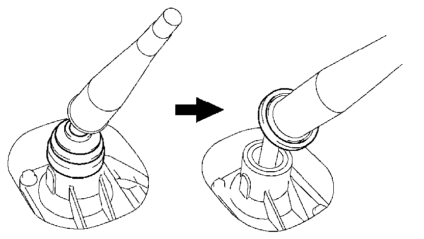
7. REMOVE FLOOR SHIFT SHIFT LEVER ASSEMBLY
a. Separate the shift lever cap boot from the manual transmission.
Pic 18
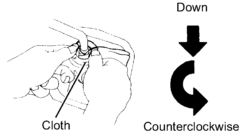
b. Cover the shift lever cap with a cloth.
C. Pressing down on the shift lever cap, turn it counterclockwise to remove the shift lever.
D. Pull out the shift lever.
8. REMOVE NO. 2 ENGINE UNDER COVER
9. DRAIN MANUAL TRANSMISSION OIL
a. Remove the drain plug, gasket and then drain the manual transmission oil.
B. Install a new gasket and drain plug.
Torque: 37 Nm (377 kgf-cm, 27 ft. Lbs.)
10. REMOVE EXHAUST PIPE ASSEMBLY
11. REMOVE FRONT PROPELLER SHAFT ASSEMBLY
12. REMOVE PROPELLER WITH CENTER BEARING SHAFT ASSEMBLY
pic 19
13. REMOVE NO. 2 MANIFOLD STAY
a. Remove the 3 bolts and manifold stay No. 2.
Pic 20
14. REMOVE MANIFOLD STAY
a. Remove the 3 bolts and manifold stay
15. REMOVE STARTER ASSEMBLY
16. REMOVE NO. 1 CLUTCH HOUSING COVER
17. REMOVE CLUTCH RELEASE CYLINDER ASSEMBLY
18. REMOVE CLUTCH ACCUMULATOR ASSEMBLY
19. SUPPORT MANUAL TRANSMISSION WITH TRANSFER
a. Support the manual transmission with a transmission jack.
Pic 21
20. REMOVE NO. 3 FRAME CROSSMEMBER SUB-ASSEMBLY
a. Remove the 4 bolts on the frame crossmember subassembly No. 3.
B. Remove the 4 nuts, 4 bolts and frame crossmember sub-assembly No. 3.
Pic 22
21. REMOVE NO. 1 ENGINE MOUNTING INSULATOR REAR
a. Remove the 4 bolts and engine mounting insulator rear from the manual transmission.
22. DISCONNECT CONNECTOR
a. Tilt down the transmission.
B. Disconnect the transfer shift actuator connector.
C. Disconnect the transfer indicator switch No. 1 connector.
D. Disconnect the transfer indicator switch No. 2 connector.
E. Disconnect the speedometer sensor connector.
F. Disconnect the back up lamp switch connector.
23. DISCONNECT WIRE HARNESS
pic 23
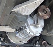
24. REMOVE MANUAL TRANSMISSION WITH TRANSFER
a. Remove the 9 bolts.
B. Separate and remove the manual transmission.
Pic 24
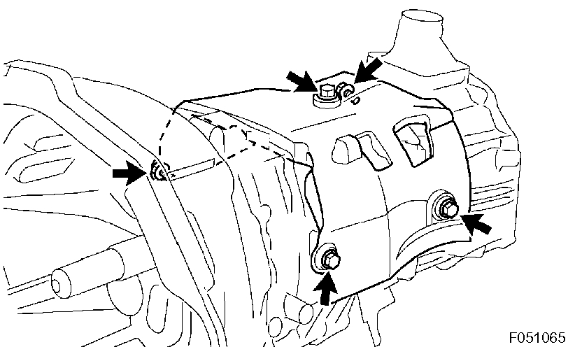
25. REMOVE MANUAL TRANSMISSION CASE COVER SUB-ASSEMBLY
a. Remove the 5 bolts and manual transmission case cover.
26. REMOVE TRANSFER ASSEMBLY
_____________________________________
Transmission Replacement
TRANSMISSION INSTALLATION
INSTALLATION
1. INSTALL TRANSFER ASSEMBLY
pic 25
2. INSTALL MANUAL TRANSMISSION CASE COVER SUB-ASSEMBLY
a. Install the manual transmission case cover with the 5 bolts.
Torque: 12 Nm (117 kgf-cm, 8.5 ft. Lbs.)
pic 26
3. INSTALL MANUAL TRANSMISSION WITH TRANSFER
a. Install the manual transmission with transfer with the 9 bolts.
Torque:
72 Nm (730 kgf-cm, 53 ft. Lbs.) For bolt A
37 Nm (380 kgf-cm, 28 ft. Lbs.) For bolt B
4. CONNECT WIRE HARNESS
pic 27
5. INSTALL NO. 1 ENGINE MOUNTING INSULATOR REAR
a. Install the engine mounting insulator rear No. 1 with the 4 bolts.
Torque: 65 Nm (663 kgf-cm, 48 ft. Lbs.)
pic 28
6. INSTALL NO. 3 FRAME CROSSMEMBER SUB-ASSEMBLY
a. Install the frame crossmember sub-assembly No. 3 with the 4 bolts and 4 nuts.
Torque: 40 Nm (408 kgf-cm, 30 ft. Lbs.)
b. Install the frame crossmember sub-assembly No. 3 with the 4 bolts.
Torque: 19 Nm (189 kgf-cm, 14 ft. Lbs.)
7. INSTALL CLUTCH ACCUMULATOR ASSEMBLY
8. INSTALL CLUTCH RELEASE CYLINDER ASSEMBLY
9. INSTALL NO. 1 CLUTCH HOUSING COVER
10. INSTALL STARTER ASSEMBLY
pic 29
11. INSTALL MANIFOLD STAY
a. Install the manifold stay with the 3 bolts.
Torque: 40 Nm (408 kgf-cm, 30 ft. Lbs.)
pic 30
12. INSTALL NO. 2 MANIFOLD STAY
a. Install the manifold stay No. 2 with the 3 bolts.
Torque: 40 Nm (408 kgf-cm, 30 ft. Lbs.)
13. INSTALL PROPELLER WITH CENTER BEARING SHAFT ASSEMBLY
14. INSTALL FRONT PROPELLER SHAFT ASSEMBLY
15. INSTALL EXHAUST PIPE ASSEMBLY
16. ADD MANUAL TRANSMISSION OIL
17. ADJUST MANUAL TRANSMISSION OIL
18. INSTALL NO. 2 ENGINE UNDER COVER
pic 31
19. INSTALL FLOOR SHIFT SHIFT LEVER ASSEMBLY
a. Apply MP grease to the tip of the shift lever.
Pic 32
b. Cover the shift lever cap with a cloth.
C. Pressing down on the shift lever cap, turn it clockwise to install the shift lever.
20. INSTALL SHIFT LEVER BOOT ASSEMBLY
a. Install the shift lever boot with the 2 screws and 2 clips.
21. INSTALL FRONT CONSOLE BOX
22. INSTALL SHIFT LEVER KNOB SUB-ASSEMBLY
23. INSTALL REAR CONSOLE BOX ASSEMBLY
24. INSTALL CONSOLE UPPER REAR PANEL SUB-ASSEMBLY
25. CONNECT CABLE TO NEGATIVE BATTERY TERMINAL
Torque: 3.9 Nm (40 kgf-cm, 35 inch lbs.)
____________________________________________
I told you it wasn't a fun job. LOL With all of that, you make the decision. If you need help, let me know.
Take care,
Joe
Images (Click to make bigger)
Sunday, April 14th, 2019 AT 2:41 PM