Okay, thanks
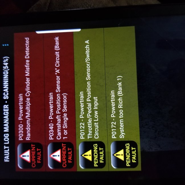
I attached the descriptions and the flow charts for the 122, 340 and the 172.
You never gave me the code for the O2 sensor.
Let me know if you have any other questions.
Roy
172
SYSTEM DESCRIPTION
A Closed Loop air/fuel metering system is used to provide the best possible combination of driveability, fuel economy, and emission control. While in a Closed Loop operation, the Power-train Control Module (PCM) monitors the oxygen sensor signal voltage and adjusts the fuel delivery based on the signal voltage. The long term fuel trim values and the short term fuel trim values can indicate any changes to the fuel delivery. Monitor the scan tool for these changes. The ideal fuel trim values are around 128 (0 percent). If the oxygen sensor signal is indicating a lean condition, the PCM will add fuel resulting in fuel trim values above 128 (0 percent to 100 percent). If you detect a rich condition, the fuel trim values will be below 128 (0 percent to -100 percent), indicating that the PCM is reducing the amount of fuel delivered. If the exhaust emissions reach an excessive level due to a lean or a rich condition, a fuel trim DTC is set.
CONDITIONS FOR RUNNING THE DTC
DTCs P0105, P0107, P0108, P0112, P0113, P0117, P0118, P0122, P0123, P0125, P0131, P0132, P0133, P0134, P0201, P0202, P0203, P0204, P0300, P0325, P0335, P0341, P0342, P0446, P0502, P0503, P0506, P0507, P0601, P0602, P1133, and P1441 not set.
Intake Air Temperature (IAT) is between -25°C (-13°F) and 115°C (175°F).
Engine coolant temperature is between 60°C (140°F) and 115°C (239°F).
Engine speed is between 550 RPM and 3400 RPM.
Vehicle speed is below 116 km/h (72 mph).
MAP is above 26 kPa
BARO is more than 72 kPa
EVAP purge is not occurring
CONDITIONS FOR SETTING THE DTC
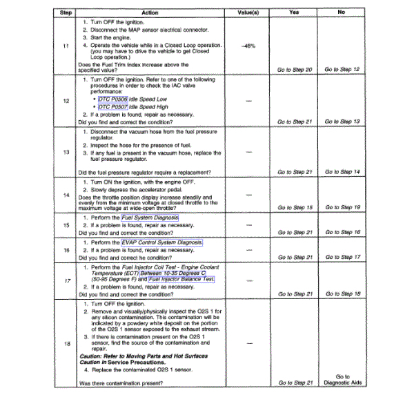
Fuel Trim Index is below 70 (-46 percent).
Above conditions present for over 16 seconds.
ACTION TAKEN WHEN THE DTC SETS
The Malfunction Indicator Lamp (MIL) will illuminate if the fault is active within the same conditions for two out of eighty ignition cycles.
Or
The MIL will illuminate after two consecutive ignition cycles in which the diagnostic runs with the fault active.
The PCM will record the operating conditions at the time that the diagnostic fails. This information will store in the Freeze Frame and Failure Records buffers.
A history DTC will store.
The coolant fan turns ON.
CONDITIONS FOR CLEARING THE MIL/DTC
The MIL turns OFF after three consecutive ignition cycles during which the diagnostic runs without a fault present under the Freeze Frame conditions that existed when the DTC failed.
A history DTC clears after 40 consecutive warm up cycles without a fault.
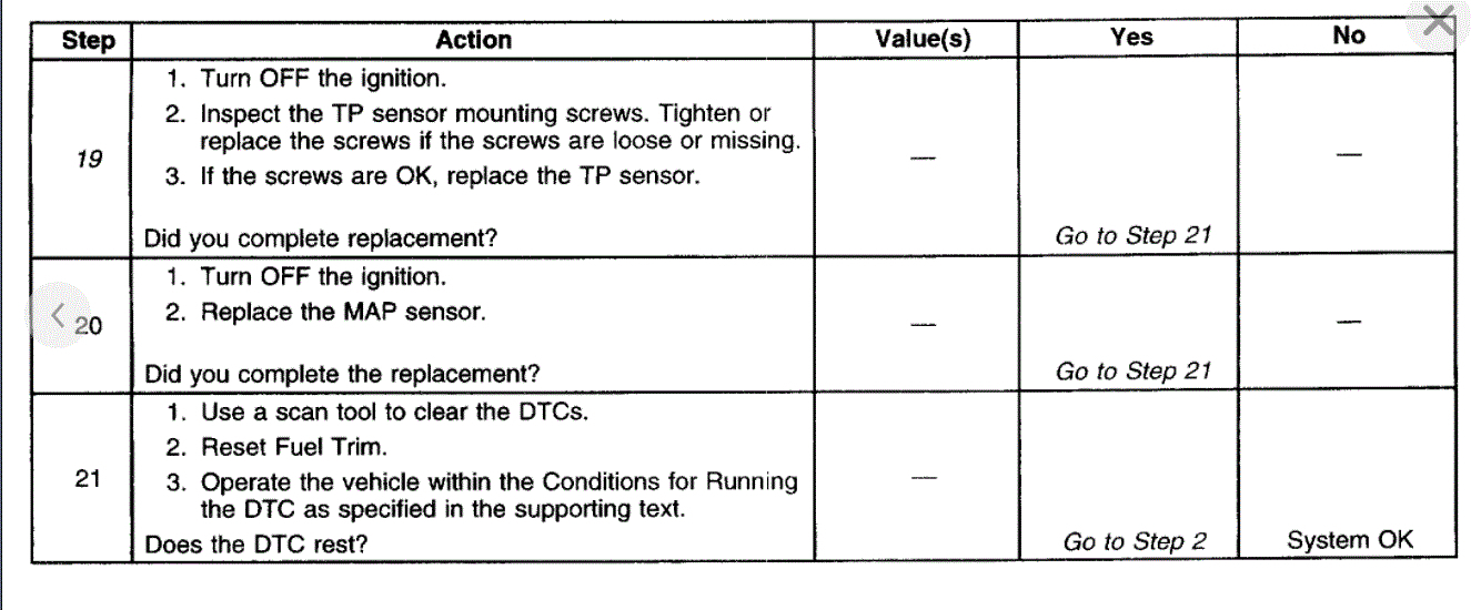
Use a scan tool to clear the DTCs.
DIAGNOSTIC AIDS
IMPORTANT: After repairs, use the scan tool Fuel Trim Reset function in order to reset the long term fuel trim to 128 (0 percent).
Check for a poor electrical connection at the PCM. Inspect the harness connectors for the following conditions:
Backed out terminals
Improper mating
Broken locks
Improperly formed electrical connectors
Damaged terminals
A poor terminal to wire connection
Inspect the wiring harness for damage. If the harness appears to be OK, observe the O2S 1 display on the scan tool while moving the electrical connectors and the wiring harness related to the engine harness. A change in the display will indicate the location of the malfunction.
Test for a contaminated crankcase.
Inspect for a restricted intake manifold.
Inspect for a restricted exhaust system.
A shorted 5 volt reference circuit may cause a DTC P0172 to set. Test the 5 volt reference sensors for abnormal readings.
TEST DESCRIPTION
The number(s) below refer(s) to the step number(s) on the Diagnostic Table.
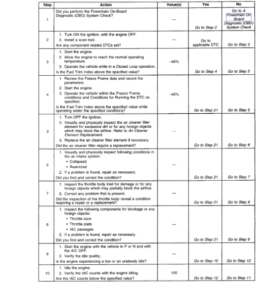
5. A clogged air cleaner filter element restricts the airflow coming into the engine. This step inspects the condition of the air cleaner filter.
17. A leaky fuel injector can cause a rich condition and set DTC P0172.
19. A loose TP sensor may not set a TP sensor related DTC, but could cause the system to become rich by a higher than actual TP reading.
340
CIRCUIT DESCRIPTION
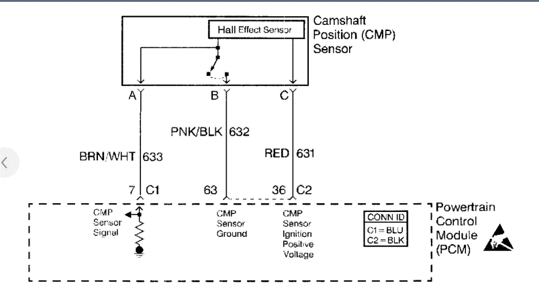
The Camshaft Position (CMP) sensor correlates the crankshaft to camshaft position so that the Powertrain Control Module (PCM) can determine which cylinder is ready to be fueled by the injector. The CMP sensor also determines which cylinder is misfiring when a misfire is present. If the PCM receives an intermittent signal from the CMP, then the CMP Resync Counter will increment. When the PCM cannot use the information from the CMP sensor, a DTC is set and the PCM will fuel the engine by using the Alternating Synchronous Double Fire (ASDF) method.
CONDITIONS FOR RUNNING THE DTC
The engine is running.
CONDITIONS FOR SETTING THE DTC
The CMP Active Counter is not incrementing.
ACTION TAKEN WHEN THE DTC SETS
The Malfunction Indicator Lamp (MIL) will illuminate after two consecutive ignition cycles in which the diagnostic runs with the fault active.
The PCM records the operating conditions at the time when the diagnostic fails. This information stores in the Freeze Frame and Failure Records buffers.
A history DTC stores.
The coolant fan turns ON.
CONDITIONS FOR CLEARING THE MIL/DTC
The MIL will turn OFF after three consecutive ignition cycles in which the diagnostic runs without a fault.
A history DTC will clear after 40 consecutive warm-up cycles without a fault.
The MIL/DTCs can be cleared by using the scan tool.
DIAGNOSTIC AIDS
An Intermittent problem may be caused by the following conditions:
Poor electrical connections
Rubbed-through wire insulation
Broken wire inside the insulation
Thoroughly check any suspected circuitry for the following conditions:
Backed-out terminals
Improper mating
Broken locks
Improperly formed connectors
Damaged terminals
Poor terminal-to-wire connections
Physical damage to the wiring harness
TEST DESCRIPTION
The numbers below refer to the step numbers on the Diagnostic Table.
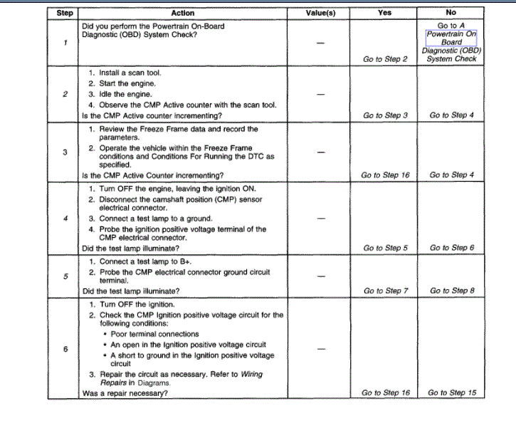
1. The Powertrain OBD System Check prompts you to complete some of the basic checks and to store the Freeze Frame and Failure Records data on the scan tool, if applicable. This creates an electronic copy of the data that was captured when the malfunction occurred. The scan tool stores this data for later reference.
2. This step determines if the DTC P0342 is the result of a hard malfunction or an intermittent condition.
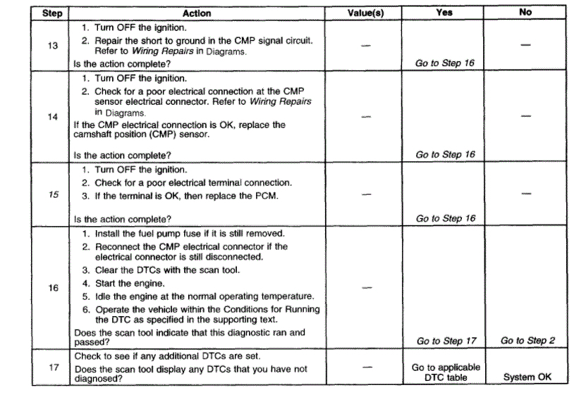
4. This step determines if the voltage is available to the CMP sensor through the PCM.
5. This step determines if the voltage is available to the CMP sensor through the PCM.
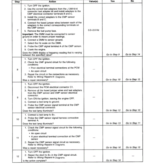
7. This step checks the output of the CMP sensor. If there is a varying voltage, then the problem is in the CMP signal circuit. If there is no varying voltage, then problem is in the CMP sensor electrical connections or is a malfunctioning CMP sensor.
15. Reprogram the replacement PCM and perform the crankshaft position system variation learn procedure. Refer to the latest Techline(TM) procedures for PCM reprogramming. Refer to CKP System Variation Learn Procedure for the crankshaft position system variation learn procedure. See: Crankshaft Position Sensor > Programming and Relearning > CKP System Variation Learn Procedure
122
CIRCUIT DESCRIPTION
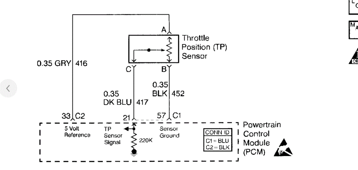
The PCM supplies a 5.0 V reference signal and a ground to the sensor. The TP sensor sends a voltage signal back to the PCM relative to the throttle plate opening. The voltage will vary from approximately 0.35 V at closed throttle, to over 4.65 V at wide open throttle.
CONDITIONS FOR RUNNING THE DTC
The engine is running.
CONDITIONS FOR SETTING THE DTC
The TP sensor reads less than 0.20 volts for 15 seconds.
ACTION TAKEN WHEN THE DTC SETS
The Malfunction Indicator Lamp (MIL) will illuminate after two consecutive ignition cycles in which the diagnostic runs with the fault active.
The PCM will record the operating conditions at the time that the diagnostic fails. This information will store in the Freeze Frame and Failure Records buffers.
A history DTC stores.
The coolant fan turns ON.
The TP angle will default to 0 percent when the vehicle speed is less than 3 km/h (2 mph) and 10 percent when the vehicle speed is greater than 3 km/h (2 mph) (The scan tool will display the defaulted value).
CONDITIONS FOR CLEARING THE MIL/DTC
The MIL will turn OFF after three consecutive ignition cycles in which the diagnostic runs without a fault.
A history DTC will clear after 40 consecutive warm up cycles without a fault.
The MIL/DTCs Can be cleared by using the scan tool.
DIAGNOSTIC AIDS
If a DTC P0122 cannot be duplicated, the information included in the Freeze Frame data can be useful. Use the scan tool DTC information data in order to determine the status of the DTC. If the DTC occurs intermittently, use the DTC P0105 Diagnostic table in order to help isolate the problem.
TEST DESCRIPTION
The number(s) below refer(s) to the step number(s) on the Diagnostic Table.
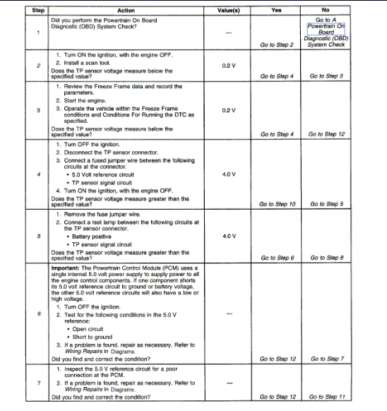
2. The TP sensor has an auto zeroing feature. If the voltage reading is between 0.20 Volts and 0.90 Volts, the PCM will automatically assume this as a closed throttle position (0 percent).
4. This simulates a DTC P0123. If the PCM recognizes the high voltage signal, this indicates that the PCM and the wiring are OK.
5. This simulates a high voltage signal which will identify an open in the signal circuit.
IMPORTANT: The Powertrain Control Module (PCM) uses a single internal 5.0 volt power supply to supply power to all the engine control components. If one component shorts its 5.0 volt reference circuit to ground or battery voltage, the other 5.0 volt reference circuits will also have a low or high voltage.
6. If any additional DTCs are set, check the 5.0 Volt reference circuits for a short to ground.
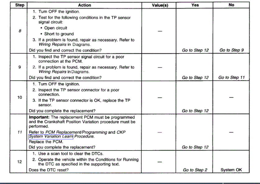
8. If the test lamp illuminates while probing the TP signal circuit terminal in step 5, then the TP signal circuit is shorted to ground.
11. Reprogram the replacement PCM and perform the Crankshaft Position System Variation Learn procedure.
Images (Click to make bigger)
Thursday, July 1st, 2021 AT 10:52 AM