Good afternoon,
I attached the location and the connector diagram for the VCM.
https://www.2carpros.com/articles/how-to-check-wiring
I also attached the location of both fuse boxes inside the truck. One under the dash and one on the end of the dash behind a pop panel.
https://www.2carpros.com/articles/how-to-check-a-car-fuse
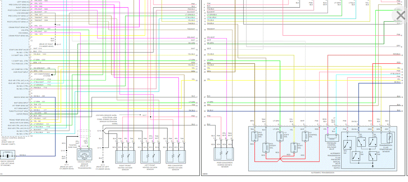
I also attached the wiring diagram for the fuel pump relay.
If you have a test light and voltmeter we can do some checks.
Roy
VEHICLE CONTROL MODULE (VCM) REPLACEMENT/PROGRAMMING
The service of the VCM consists of replacing the VCM. If the diagnostics call for replacement of the VCM, transfer the Knock Sensor (KS) Calibration Programmable Read Only Memory (PROM) and program the EEPROM in the VCM. Refer to Electrically Erasable Programmable Read Only Memory (EEPROM) Programming.
KNOCK SENSOR (KS) CALIBRATION PROM
CAUTION: In order to prevent possible Electrostatic Discharge damage to the VCM, do not touch the connector pins or soldered components on the circuit board. In order to prevent the internal VCM damage, the ignition must be OFF when disconnecting or reconnecting or reconnecting the power to the VCM (battery cable, ECM fuse, jumper cables, etc.).
REMOVAL PROCEDURE
1. Disconnect the negative battery cable.
2. Remove the connectors from the VCM.
3. Remove the mounting hardware. Remove the VCM from the engine compartment.
4. Remove the VCM access cover.
CAUTION: Do not remove the cover of the KS Calibration PROM. Use of an unapproved KS Calibration PROM removal methods may cause damage to the KS Calibration PROM or the socket.
NOTE: The replacement VCM is supplied without a KS Calibration PROM, so for reuse in the new VCM carefully remove the PROM from the defective VCM.
5. Remove the Calibration PROM.
5.1.Using the thumb and first finger, remove the KS Calibration PROM by gently squeezing each end of the blue KS Calibration PROM
5.2.Pull upward.
6. Inspect for the alignment notches of the KS Calibration PROM.
7. Carefully set it aside.
8. Do not open the KS Calibration PROM.
9. Remove the new VCM from the packaging. Check the service number in order to make sure it is the same as the defective VCM.
10. Remove the access cover.
INSTALLATION PROCEDURE
NOTE: Press only on the ends of the KS Calibration PROM. The small notches in the KS Calibration PROM must align with the small notches in the KS Calibration PROM socket. Gently press on the KS Calibration PROM until it is firmly seated in the socket. Listen for the click.
1. Install the KS Calibration PROM in the KS Calibration PROM socket.
2. Install the access cover on the VCM.
3. Install the VCM in the engine compartment.
NOTE: The ignition should always be OFF when installing or removing the VCM connectors.
4. Install the connectors to the VCM.
5. The MIL, antilock and brake lamps will continue to be enabled until the VCM is programmed. Once the programming is complete, the lamps will turn off and normal operation will occur.
6. Connect the negative battery cable.
7. Proceed to the EEPROM programming. Refer to EEPROM Programming.
REPROGRAMING (FLASHING) THE CONTROL MODULE
Some vehicles allow the reprogramming of the control module without removal from the vehicle. This provides a flexible and a cost-effective method of making changes in software and calibrations.
Refer to the latest Techline information on re-programming or flashing procedures.
Images (Click to make bigger)
SPONSORED LINKS
Saturday, September 19th, 2020 AT 2:49 PM