It sound like the instrument cluster is going out. If you get a used one it might need to be programmed at a shop. Here is a diagram that will help you remove the unit. (Below)
Here is a troubleshooting guide
INSTRUMENT CLUSTER
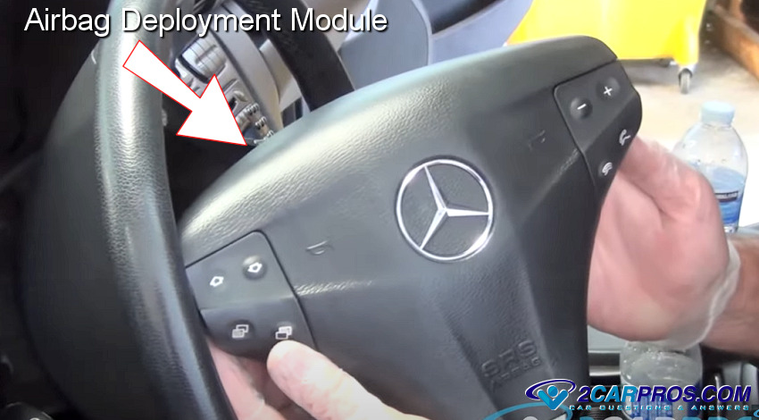
WARNING: disable the Supplemental Restraint System (SRS) before attempting any steering wheel, steering column, airbag, seat belt tensioner, impact sensor, or instrument panel component diagnosis or service. Disconnect and isolate the negative battery (ground) cable, then wait two minutes for the system capacitor to discharge before performing further diagnosis or service. This is the only sure way to disable the SRS. Failure to these instructions may result in accidental airbag deployment and possible serious or fatal injury.
If all of the instrument cluster gauges and indicators are ineffective, be certain to check the instrument cluster fused B(+) fuse and the instrument cluster fused B(+) and ground circuits for shorts or opens. Refer to the appropriate wiring information. The wiring information includes wiring diagrams, proper wire and connector repair procedures, details of wire harness routing and retention, connector pin-out information and location views for the various wire harness connectors, splices and grounds.
If an individual hard wired gauge or indicator is inoperative, refer to the diagnosis and testing service information for that specific gauge or indicator. If an individual Controller Area Network (CAN) or Local Interface Network (LIN) data bus message-controlled gauge or indicator is inoperative, perform the Self-Test as follows:
CAUTION: Instrument clusters used in this vehicle automatically configure themselves for compatibility with the features and optional equipment in the vehicle in which they are initially installed. The instrument cluster is programmed to do this by embedding the Vehicle Identification Number (VIN) and other information critical to proper cluster operation into electronic memory. This embedded information is learned through electronic messages received from other electronic modules in the vehicle over the Controller Area Network (CAN) data bus, and through certain hard-wired inputs received when the cluster is connected to the vehicle electrically. Once configured, the instrument cluster memory may be irreparably damaged and certain irreversible configuration errors may occur if the cluster is connected electrically to another vehicle; or, if an electronic module from another vehicle is connected that provides data to the instrument cluster (including odometer values) that conflicts with that which was previously learned and stored. Therefore, the practice of exchanging (swapping) instrument clusters and other electronic modules in this vehicle with those removed from another vehicle must always be avoided. Failure to observe this caution may result in instrument cluster damage, which is not reimbursable under the terms of the product warranty.
Service replacement instrument clusters are provided with the correct VIN, and the certified odometer values embedded into cluster memory, but will otherwise be automatically configured for compatibility with the features and optional equipment in the vehicle in which they are initially installed.
NOTE: Certain indicators in this instrument cluster are automatically configured. This feature allows those indicators to be activated or deactivated for compatibility with certain optional equipment. If the problem being diagnosed involves improper illumination of the cruise indicator, the electronic throttle control indicator, the fog lamp indicator, the security indicator or the gear selector indicator, disconnect and isolate the battery negative cable. After about five minutes, reconnect the battery negative cable and turn the ignition switch to the ON position. The instrument cluster should automatically relearn the equipment in the vehicle and properly configure the configurable indicators accordingly.
SELF-TEST
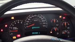
The instrument cluster self-test will put the instrument cluster into its diagnostic mode. In this mode the instrument cluster can perform a self-diagnostic test that will confirm that the instrument cluster circuitry, the gauges and the indicators are capable of operating as designed. During the self-test the instrument cluster circuitry will position each of the gauge needles at various calibration points, illuminate each of the segments in the Vacuum-Fluorescent Display (VFD) units, and turn all of the indicators ON and OFF again.
Successful completion of the self-test will confirm that the instrument cluster is operational. However, there may still be a problem with the CAN or LIN data bus, the Powertrain Control Module (PCM) or Engine Control Module (ECM) (depending on engine application), the Totally Integrated Power Module (TIPM), the Controller Antilock Brake (CAB), the Occupant Restraint Controller (ORC), the compass module, the Wireless Ignition Node (WIN), the Steering Wheel Switch Module (SWSM), the Steering Control Module (SCM) or the inputs to one of these electronic control modules. Use a diagnostic scan tool to diagnose these components. Refer to the appropriate diagnostic information.
Begin the self-test with the ignition switch in the OFF position.
Depress the odometer/trip odometer switch button.
While still holding the odometer/trip odometer switch button depressed, turn the ignition switch to the ON position, but do not start the engine.
Release the odometer/trip odometer switch button.
The instrument cluster will simultaneously begin to illuminate all of the operational segments in the VFD units, and perform a bulb check of each operational bus message-controlled LED indicator. The VFD segments and LED indicators remain illuminated as each gauge needle is swept to several calibration points and back. If a VFD segment or an LED indicator fails to illuminate, or if a gauge needle fails to sweep through the calibration points and back during this test, the instrument cluster must be replaced.
The instrument cluster self-test is now completed. The instrument cluster will automatically exit the diagnostic mode and return to normal operation at the completion of the test. The instrument cluster self-test will be aborted if the ignition switch is turned to the OFF position, or if the ignition switch is turned to the START position.
Go back to 1 to repeat the instrument cluster self-test, if necessary.
I would try disconnecting and reconnecting the cluster to clean any bad connections just to see if that was the problem.
Please let us know what you find. I'm interested to see what it is.
Cheers, Ken
Images (Click to make bigger)
SPONSORED LINKS
Monday, October 23rd, 2017 AT 1:27 PM