P0102 Mass Air Flow Low Frequency code with good MAF

Tiny
CLANOFWOLVES
  • MEMBER
  • 1997 CHEVROLET LUMINA
  • 3.1L
  • 6 CYL
  • 2WD
  • AUTOMATIC
  • 933,000 MILES
Just test drove her again and got the error code:
PO102
Mass of Volume Air Flow A
Circuit Low

I replaced the MAF a few days ago. So I removed the new plastic one and replaced it with the original aluminum one (that's clean as a whistle) and there was no change in the error code. Plus, I then tested it with my multi-meter, here are the results:

1) With the harness disconnected and the engine/ignition off:
All three wires (red, black and yellow) ohm-ed out as ground.
2) With the key in the ignition and it turned to run position without the engine on:
The power wire (red) had almost 13 volts, the ground (black) wire was grounded, and the signal wire had about 6 volts.
3) With the engine running and the harness attached:
I tested the Hertz with my test bench set to 20 Hertz and the signal wire (yellow) had a fairly consistent 2.14 hertz at idle (engine warm) and when the engine revved it smoothly went to just above 14 hertz and then evenly went back down to 2.14 when the idle was slowly released.   

​​​​​​​So it seems the original MAF is working within specifications? So why is this code thrown?
Tuesday, March 10th, 2020 AT 1:47 PM

63 Replies

Tiny
ASEMASTER6371
  • MECHANIC
  • 52,797 POSTS
Good afternoon,

I attached a flow chart for you to follow.

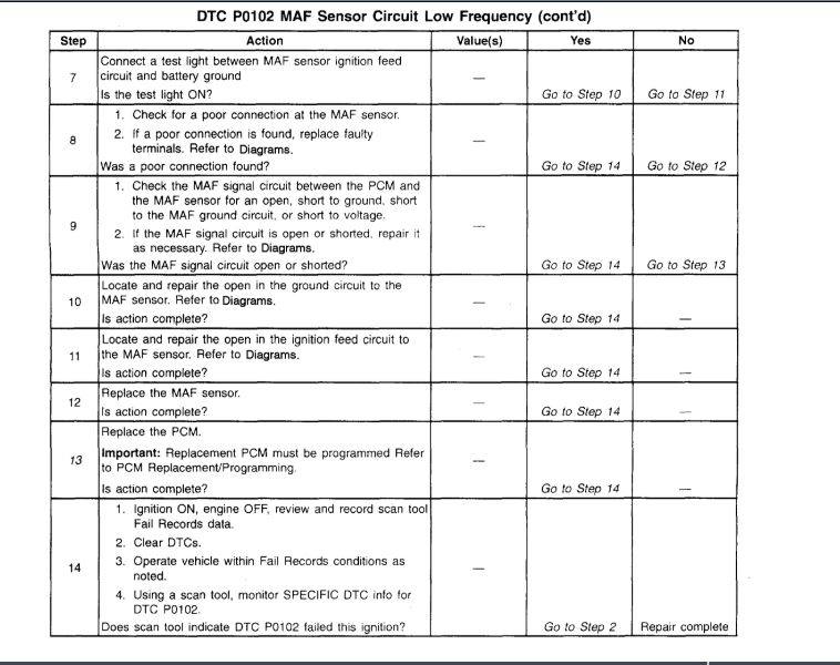
Follow the steps and let me know what you find.

Roy

Circuit Description

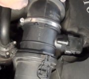
The Mass Air Flow (MAF) sensor measures the amount of air which passes through it into the engine during a given time. The PCM uses the mass air flow information to monitor engine operating conditions for fuel delivery calculations. A large quantity of air entering the engine indicates an acceleration or high load situation, while a small quantity of air indicates deceleration or idle.

The MAF sensor produces a frequency signal which can be monitored using a scan tool. The frequency will vary within a range of around 2000 Hertz at idle to near 10,000 Hertz at maximum engine load. DTC P0102 will be set if the signal from the MAF sensor is below the possible range of a normally operating MAF sensor.

Conditions for Setting the DTC

The engine is running.

MAF signal frequency is below 1200 Hertz.

Above conditions present for over 0.5 seconds.

Throttle angle below 75%.

Action Taken When the DTC Sets

The PCM will illuminate the Malfunction Indicator Lamp (MIL) during the first trip in which the diagnostic test has been run and failed.

The PCM will store conditions which were present when the DTC set as Freeze Frame and Fail Records data.

Conditions for Clearing the MIL/DTC

The PCM will turn the MIL OFF during the third consecutive trip in which the diagnostic has been run and passed.

The history DTC will clear after 40 consecutive warm-up cycles have occurred without a malfunction.

The DTC can be cleared by using the scan tool Clear Info function or by disconnecting the PCM battery feed.

Diagnostic Aids

Check for the following conditions:

Poor connection at PCM. Inspect harness connectors for backed out terminals, improper mating, broken locks, improperly formed or damaged terminals, and poor terminal to wire connection.

Misrouted harness. Inspect the MAF sensor harness to ensure that it is not routed too close to high voltage wires such as spark plug leads.

Damaged harness. Inspect the wiring harness for damage. If the harness appears to be OK, observe the scan tool while moving connectors and wiring harnesses related to the MAF sensor. A change in the display will indicate the location of the fault.

Plugged intake air duct or filter element. A wide open throttle acceleration from a stop should cause the Mass Air Flow displayed on a scan tool to increase from about 4-7 gm/s at idle to 100 gm/s or greater at the time of the 1-2 shift. If not, check for a restriction.

If DTC P0102 cannot be duplicated, the information included in the Fail Records data can be useful in determining vehicle mileage since the DTC was last set.

Test Description

The numbers below refer to the step numbers on the Diagnostic Table:

2. This step verifies that the problem is present at idle.

5. A voltage reading of less than 4 or over 6 volts at the MAF sensor signal circuit indicates a fault in the wiring or a poor connection.

6. Verifies that ignition feed voltage and a good ground are available at the MAF sensor.

13. This vehicle is equipped with a PCM which utilizes an Electrically Erasable Programmable Read Only Memory (EEPROM). When the PCM is being replaced, the new PCM must be programmed. Refer to PCM Replacement and Programming Procedures.
Was this
answer
helpful?
Yes
No
+1
Tuesday, March 10th, 2020 AT 2:22 PM
Tiny
CLANOFWOLVES
  • MEMBER
  • 33 POSTS
Thanks for the information, this is a long version of what I found on-line about testing the MAF in a GM 3.1.

I originally checked all plugs and connectors and insured they were clean and used dielectric grease when reattaching them. The plenums are clear and clean and the air-box has a new filter. I ran the test for the MAF, but I don't know what range the hertz signals should be, but as I stated, it was smooth and rose and fell with the throttle.

I have a Haynes manual arriving tonight and I hope like hell it helps, as replacing parts and taking it to shops for them to tell me what I already know is getting me no where. Quite frustrating.

With the knowledge I have given, what do you think my next step is?
Was this
answer
helpful?
Yes
No
Tuesday, March 10th, 2020 AT 3:14 PM
Tiny
ASEMASTER6371
  • MECHANIC
  • 52,797 POSTS
Did you follow the flow chart and what were your results?

Roy
Was this
answer
helpful?
Yes
No
Tuesday, March 10th, 2020 AT 3:17 PM
Tiny
CLANOFWOLVES
  • MEMBER
  • 33 POSTS
I think I'm tracking with you on my Foxwell having a (g/s) reading for the MAF. It seems it was in the 4-5 during idle and was at the 40-50 range when it was bogging down, but when it cleared and accelerated as expected, it was well into the high 60's and into the 70's. Is this something that assists? Both the original GM MAF and the new replacement AC Delco MAF are performing the exact same way.
Was this
answer
helpful?
Yes
No
Tuesday, March 10th, 2020 AT 5:59 PM
Tiny
ASEMASTER6371
  • MECHANIC
  • 52,797 POSTS
Did you replace the connector to the sensor? It is very common for the connector to be faulty.

If all that is good, then a good chance the ECM is the issue.

Roy
Was this
answer
helpful?
Yes
No
Tuesday, March 10th, 2020 AT 6:03 PM
Tiny
CLANOFWOLVES
  • MEMBER
  • 33 POSTS
Interesting, I never thought the connector could be an issue. I did have the same exact issue with the new MAF sensor, and I got the clear ground, power and signal power at the wiring harness. How exactly would I check that outside of these checks.

Yes, the ECM is my next thought too. I could have the original ECM reprogrammed and/or I can have a replacement unit reprogrammed (I grabbed a $30.00 used ECM with the same model and serial numbers from a recycling yard that was in a 1997 Skylark last Saturday).
Was this
answer
helpful?
Yes
No
Wednesday, March 11th, 2020 AT 5:07 AM
Tiny
CLANOFWOLVES
  • MEMBER
  • 33 POSTS
Thanks so much BTW, you've been awesome and invaluable!
Was this
answer
helpful?
Yes
No
Wednesday, March 11th, 2020 AT 5:10 AM
Tiny
CLANOFWOLVES
  • MEMBER
  • 33 POSTS
Since I have an additional ECM, I'm thinking of downloading: http://www.mediafire.com/file/bc92by7ao7fp1la/GM_2000NAO.7z/file
and putting that Skylark ECM in the car and reprogramming it to the most recent GM default upgrade (or "flash" it as they say on line) as my daughter's Lumina VIN number and see if I can resolve the issue. All I understand that I need need is this free program, my computer and a OBDLink SX USB cable. This sound doable for a unpaid mechanic, haha?
Was this
answer
helpful?
Yes
No
Wednesday, March 11th, 2020 AT 10:08 AM
Tiny
ASEMASTER6371
  • MECHANIC
  • 52,797 POSTS
I do not think that will work. You can try it but I doubt it.

Roy
Was this
answer
helpful?
Yes
No
Wednesday, March 11th, 2020 AT 10:23 AM
Tiny
KEN L
  • MASTER CERTIFIED MECHANIC
  • 43,070 POSTS
If it does work please let us know.
Was this
answer
helpful?
Yes
No
Wednesday, March 11th, 2020 AT 2:52 PM
Tiny
CLANOFWOLVES
  • MEMBER
  • 33 POSTS
Interesting. It seems like the issue is the CMU not issuing the correct indicators to the engine components based on the MAF info it's seemingly getting. Since I have the bonus CMU, I'll try it, but what do you think is the issue is it's not the MAF even though the code says it is? Quite frustrating I'll admit.
Was this
answer
helpful?
Yes
No
Wednesday, March 11th, 2020 AT 5:39 PM
Tiny
ASEMASTER6371
  • MECHANIC
  • 52,797 POSTS
The ECM is not seeing the signal. All your readings look good but the ECM is not processing it so it is coding because it is not seeing it.

Sounds like you need an ECM.

Roy
Was this
answer
helpful?
Yes
No
Wednesday, March 11th, 2020 AT 6:24 PM
Tiny
KEN L
  • MASTER CERTIFIED MECHANIC
  • 43,070 POSTS
Lets check the connection between the PCM and MAF. here is a guide and the wiring diagrams so you can see how the system works and which wires to check:

https://www.2carpros.com/articles/how-to-check-wiring

Check out the diagrams (below). Please let us know what happens.
Was this
answer
helpful?
Yes
No
+1
Thursday, March 12th, 2020 AT 10:33 AM
Tiny
CLANOFWOLVES
  • MEMBER
  • 33 POSTS
Thanks for the advice!

I did ohm out the yellow signal wire from the MAF harness to the PCM harness pin and I got no tone and about 1.87 on the resistance. I then ran a same gauge yellow wire along the existing plastic conduit (wire bundle cover) and skinned back the existing wire just short of each harness and wrapped the new wire for good contact. I then checked the connector to connector and had tone and something like.002. I then put everything back together and drove it.

She went up hills fine but there was a slight hesitation here and there, so I plugged in my Foxwell and saw the MAF (g/s) stayed steady at 1.95 no matter my acceleration. I then thought the old wire still in the circuit might be the issue, or the original MAF sensor that I put back on was bad (I thought not as the new MAF sensor threw the same readings, but it could have been the wire). So I returned home to cut out the old wire and see how she ran back to the auto parts store to get a new MAF.

I cut the old yellow sensor wire free at both ends and wrapped the ends good. Got it to start her and she wouldn't start.

She just spun the starter.

Foxwell was connected and stated there was no error code.

So I checked a few of the fuses, they were good. I'll need to start at fuel pressure, and so one to find out what happened between leaving the old sensor wire and taking it out.

Am I missing something simple?

Frustration sets in. I need a breather for an hour or so before I get back into it.

Thanks guys!
Was this
answer
helpful?
Yes
No
Thursday, March 12th, 2020 AT 4:13 PM
Tiny
ASEMASTER6371
  • MECHANIC
  • 52,797 POSTS
How did you check the resistance?

What tool were you using?

Roy
Was this
answer
helpful?
Yes
No
Thursday, March 12th, 2020 AT 4:26 PM
Tiny
CLANOFWOLVES
  • MEMBER
  • 33 POSTS
I use my BKPrecision Test Bench 388-HD.

I checked the wire/solder and it all shows connectivity, and I checked the other pins around the MAF sensor input wire at the lower large PCM plug in case my manipulation of the wires to get to the yellow MAF sensor wire caused any damage.

Another thought: although I always disconnected the battery hot before working with the PCM or other wiring (like soldering in a new sensor wire), I didn’t disconnect the positive side of the battery to disconnect the old sensor wire I theorized might be causing signal issues. I used insulated snips, and didn’t cut any other wires, but I’m wondering about anything that could have occurred.
Was this
answer
helpful?
Yes
No
Thursday, March 12th, 2020 AT 6:59 PM
Tiny
ASEMASTER6371
  • MECHANIC
  • 52,797 POSTS
Just to be clear, did you run the overlay wire without disconnecting the original wire?

Roy
Was this
answer
helpful?
Yes
No
Friday, March 13th, 2020 AT 2:56 AM
Tiny
CLANOFWOLVES
  • MEMBER
  • 33 POSTS
Yes. Then, when it was better, but seemed a little hesitant, I theorized the original wire’s still attached and attempting to carry signal, so removing it from the carrying material might clean up the signal so the info is clearer for the PCM. Or so I thought.

I can’t help but think it’s something that got altered during the getting to and putting back of everything else.
Was this
answer
helpful?
Yes
No
Friday, March 13th, 2020 AT 4:25 AM
Tiny
ASEMASTER6371
  • MECHANIC
  • 52,797 POSTS
I agree. Are you sure you cut the correct wire? Did you verify the wire from one end to the other?

Roy
Was this
answer
helpful?
Yes
No
Friday, March 13th, 2020 AT 4:29 AM
Tiny
CLANOFWOLVES
  • MEMBER
  • 33 POSTS
I checked fuel pressure at the rail last night and it’s good. I’ll check MAF power and signal at the MAF and at the PCM connector this AM.

All the fuses, connectors, pins and wires at all of my work points checked out visually. I did see in the wiring diagram that the anti-theft and ignition wires were right next to the MAF signal wire, and they weren’t damaged, and when the wires were moved, the female pin connectors inside the harness moved, so they look fine.

I’ll just recheck everything again. Then check for spark.
Was this
answer
helpful?
Yes
No
Friday, March 13th, 2020 AT 4:30 AM

Please login or register to post a reply.

Sponsored links