Welcome to 2CarPros.
The code indicates an issue with the bank one intake valve timing. Based on what you have already done, you have replaced the hard parts that could be causing the issue. However, even a bad crankshaft position sensor could be causing the issue.
Now, you changed the oil. Was it extremely dirty? Sludge or other contaminates can be causing low pressure to the timing control solenoid. Also, there could be a wiring issue to the solenoid valve or cam sensor.
Make sure the wiring appears in good condition and the connections are not corroded or damaged.
As far as is it safe to drive, I wouldn't suggest it. The power loss and roughness is the result of a timing issue and engine damage or damage to other components can occur.
I'm a bit confused. You indicate little knowledge, but you have already done a lot of work. Since it seems you know a good bit, I am going to provide the diagnostics to help with this problem in case you want to try and diagnose it yourself. All of the attached pics will correlate with these directions. However, you will need a scan tool to perform the tests and a multi meter. Here are links for testing wiring and using a multi meter:
https://www.2carpros.com/articles/how-to-use-a-voltmeter
https://www.2carpros.com/articles/how-to-check-wiring
++++++++++++++++++++++++++++++++++++++++++++++++++
Here is the diagnostics for the code you have.
DTC P0011 IVT CONTROL
Description
pic 1
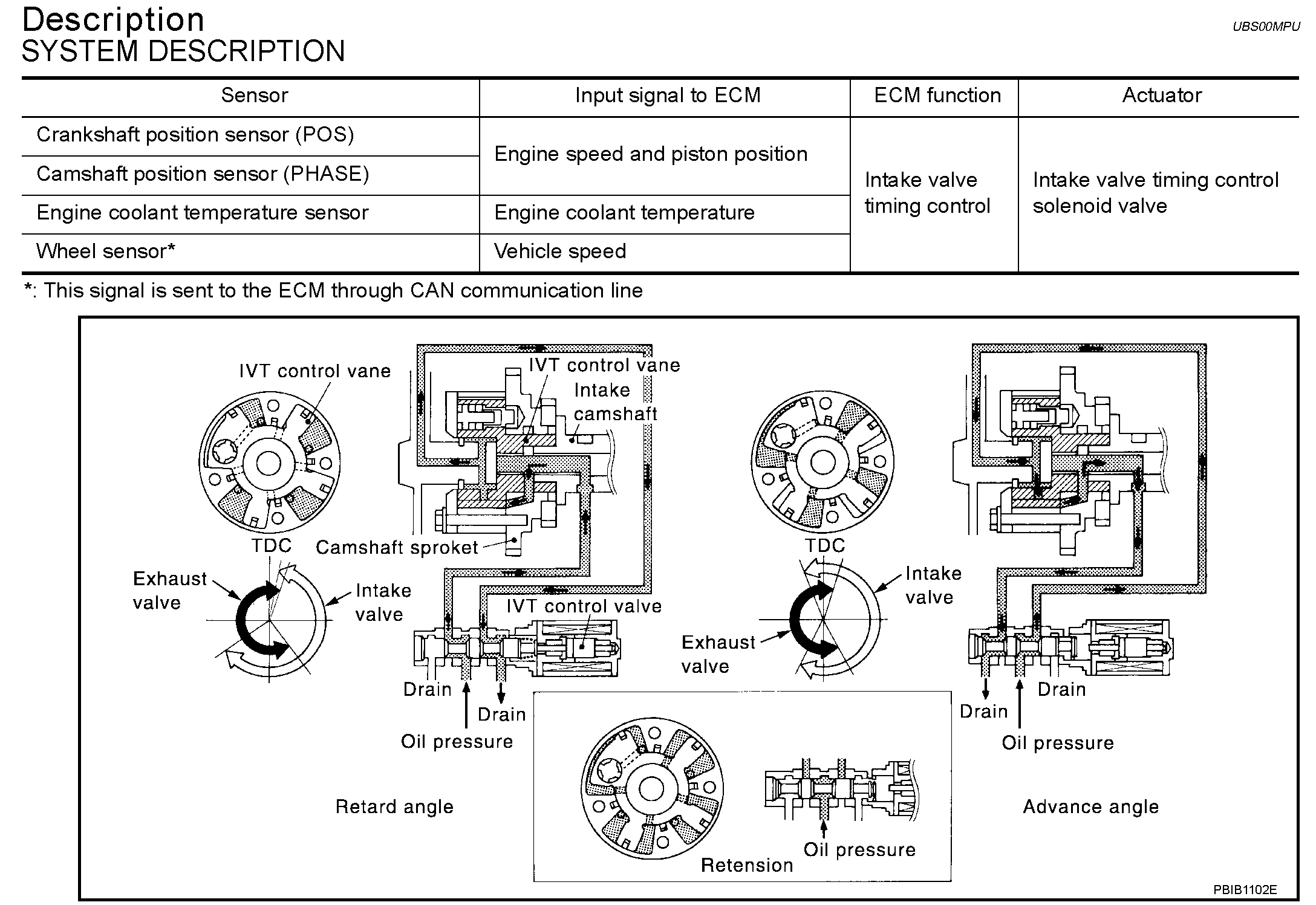
SYSTEM DESCRIPTION
This mechanism hydraulically controls cam phases continuously with the fixed operating angle of the intake valve.
The ECM receives signals such as crankshaft position, camshaft position, engine speed, and engine coolant temperature. Then, the ECM sends ON/OFF pulse duty signals to the intake valve timing control solenoid valve depending on driving status. This makes it possible to control the shut/open timing of the intake valve to increase engine torque in low/mid speed range and output in high-speed range.
pic 2
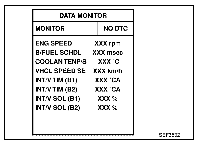
CONSULT-II Reference Value in Data Monitor Mode
pic 3
On Board Diagnosis Logic
pic 4
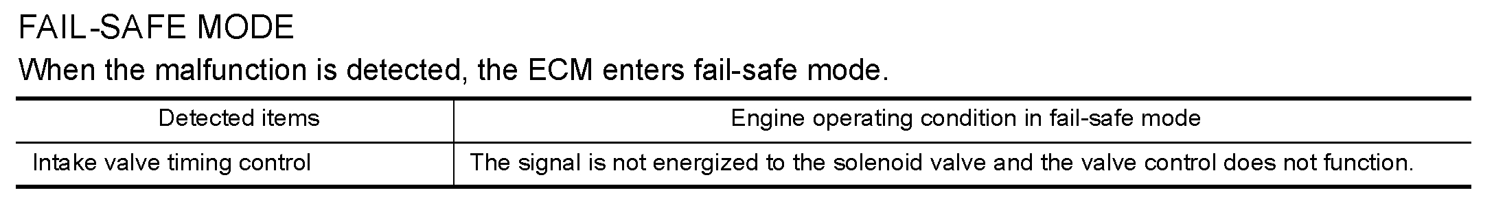
FAIL-SAFE MODE
DTC Confirmation Procedure
CAUTION: Always drive at a safe speed.
NOTE:
- If DTC P0011 or P0021 is displayed with DTC P1111 or P1136, first perform trouble diagnosis for DTC P1111 or P1136. See: A L L Diagnostic Trouble Codes ( DTC ) > P Code Charts > P1111
- If DTC Confirmation Procedure has been previously conducted, always turn ignition switch OFF and wait at least 10 seconds before conducting the next test.
TESTING CONDITION:
Before performing the following procedure, confirm that battery voltage is between 10 V and 16 V at idle.
WITH CONSULT-II
pic 5
1. Turn ignition switch ON and select "DATA MONITOR" mode with CONSULT-II.
2. Start engine and warm it up to the normal operating temperature.
pic 6
3. Maintain the given conditions for at least 6 consecutive seconds. Hold the accelerator pedal as steady as possible.
4. Stop vehicle with engine running and let engine idle for 10 seconds.
5. If the 1st trip DTC is detected, go to "Diagnostic Procedure" below.
If the 1st trip DTC is not detected, go to next step.
pic 7
6. Maintain the given conditions for at least 20 consecutive seconds.
7. If the 1st trip DTC is detected, go to "Diagnostic Procedure" below.
WITH GST
Follow the procedure "WITH CONSULT-II" above.
Diagnostic Procedure (Steps 1 - 5)
pic 8
Diagnostic Procedure (Steps 6 - 8)
pic 9
Diagnostic Procedure
Component Inspection
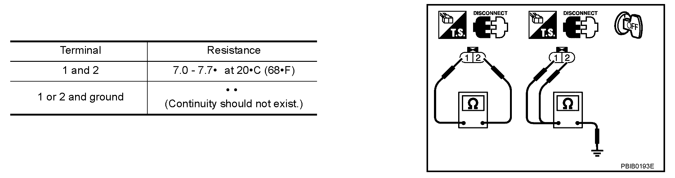
INTAKE VALVE TIMING CONTROL SOLENOID VALVE
1. Disconnect intake valve timing control solenoid valve harness connector.
pic 10
2. Check resistance between intake valve timing control solenoid valve as shown.
If NG, replace intake valve timing control solenoid valve.
If OK, go to next step.
3. Remove intake valve timing control solenoid valve.
pic 11
4. Provide 12 V DC between intake valve timing control solenoid valve terminals and then interrupt it. Make sure that the plunger moves as shown in the figure.
CAUTION:
Do not apply 12 V DC continuously for 5 seconds or more.
Doing so may result in damage to the coil in intake valve timing control solenoid valve.
If NG, replace intake valve timing control solenoid valve.
NOTE: Always replace O-ring when intake valve timing control solenoid valve is removed.
+++++++++++++++++++++++++++++++++++++++++++++++++
I added these directions in case you feel comfortable do it. Please let me know if you have questions or need additional information.
Take care,
Joe
Images (Click to make bigger)
SPONSORED LINKS
Monday, May 13th, 2019 AT 7:48 PM