Welcome to 2CarPros.
It does sound like the clutch is bad. Don't laugh, but when I question one, I take the car to a safe area and simply stop, put it in fifth gear, and let out the clutch not touching the throttle. If it stalls, it may not be the clutch. If it keeps running but you notice a load on the engine, replace the clutch.
___________________________________
If you determine the clutch needs replaced, here are the directions for removing the transmission, the clutch assembly and reinstalling everything. The attached pictures correlate with the directions.
_____________________________________
Removal and replacement
REMOVAL AND INSTALLATION
Part 1
pic 1
Part 2
pic 2
TRANSAXLE REMOVAL
pic 3
pic 4
1. REMOVE NEGATIVE BATTERY CABLE
CAUTION: Work must be started after 90 seconds from the "LOCK" position and the negative (-) terminal cable is disconnected from the battery.
2. REMOVE AIR CLEANER CASE ASSEMBLY WITH AIR HOSE
3. REMOVE CRUISE CONTROL ACTUATOR
a. Remove the cruise control actuator cover.
B. Disconnect the connector.
C. Remove the three bolts and cruise control actuator with bracket.
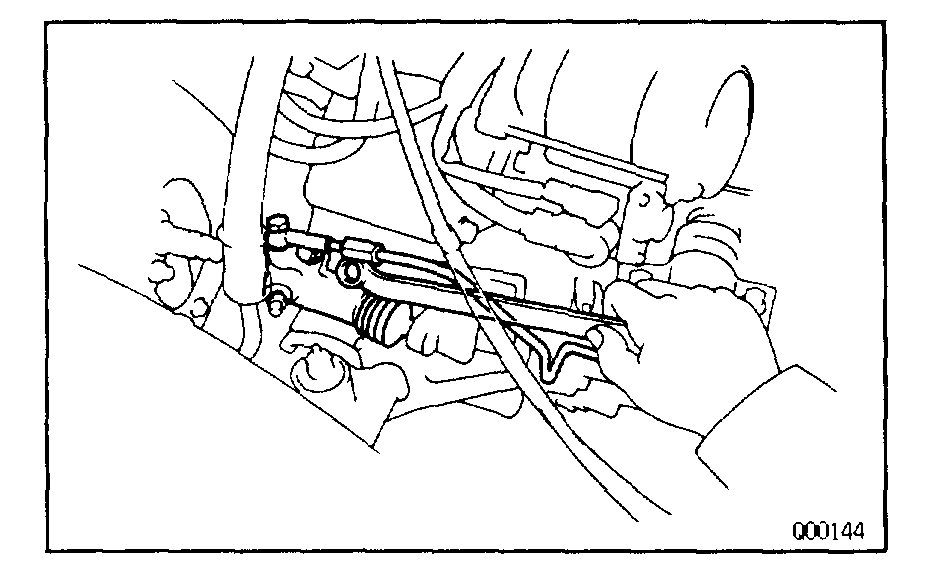
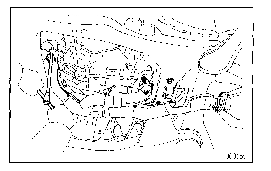
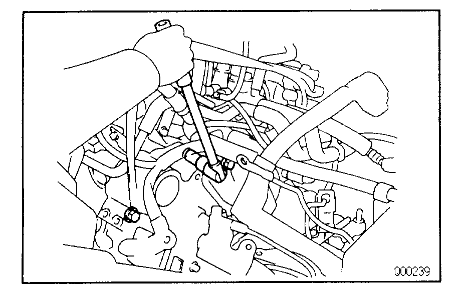
4. REMOVE CLUTCH RELEASE CYLINDER
pic 5
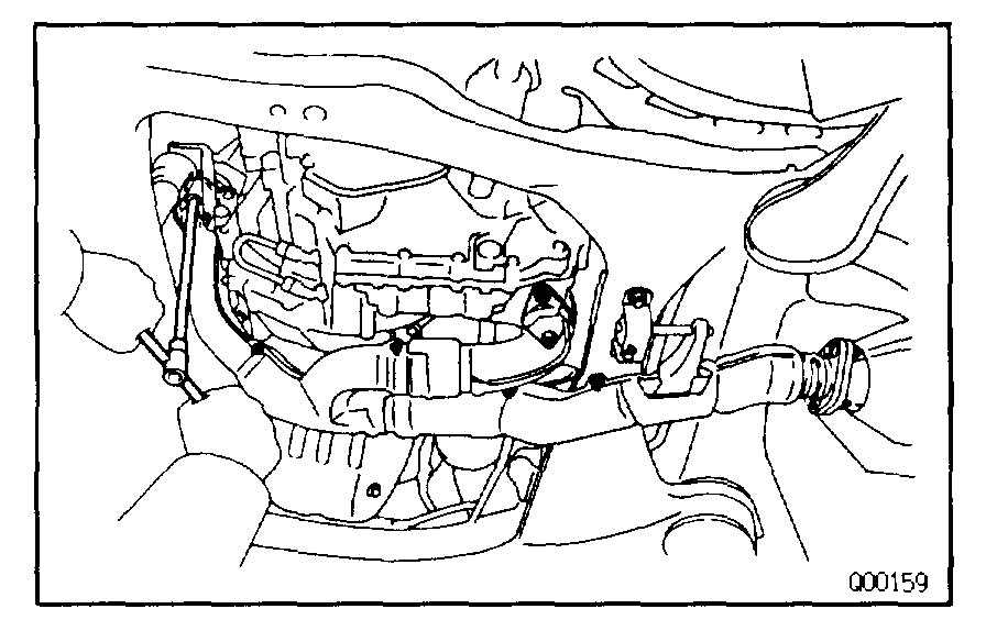
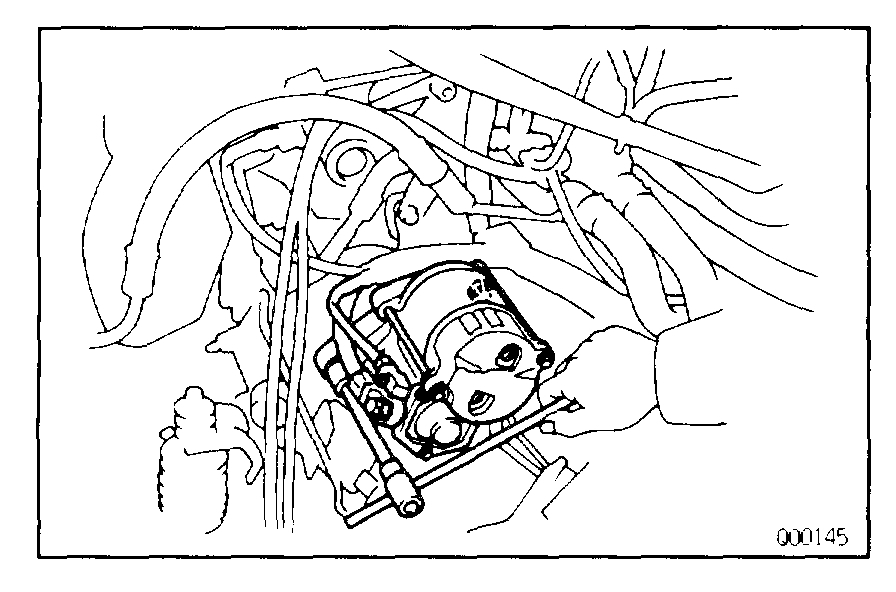
5. REMOVE STARTER
a. Disconnect the connector and wire from the starter.
B. Remove the two bolts and starter.
Pic 6
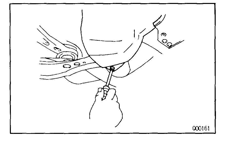
6. REMOVE CLUTCH ACCUMULATOR AND TUBE CLAMP
a. Remove the two bolts and clutch accumulator with bracket.
B. Remove the bolt and clutch tube clamp.
Pic 7
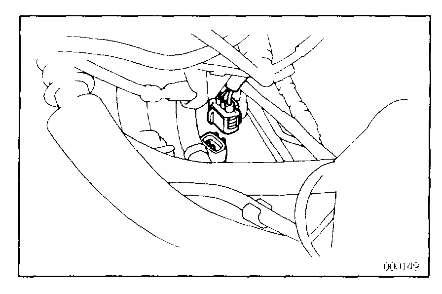
7. DISCONNECT BACK-UP LIGHT SWITCH CONNECTOR
pic 8
8. DISCONNECT WIRES CLAMPS
pic 9
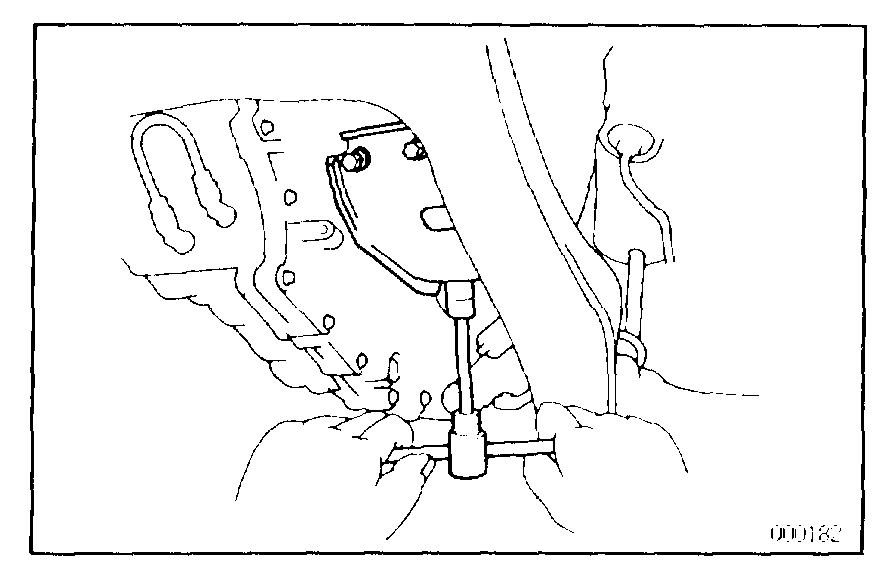
9. REMOVE CLUTCH RELEASE CYLINDER BRACKET
pic 10
10. REMOVE EARTH CABLES
pic 11
11. DISCONNECT CONTROL CABLES
a. Remove the clips and washers.
B. Remove the retainer from the cables.
Pic 12
12. REMOVE TRANSAXLE MOUNTING THREE BOLTS OF TRANSAXLE CASE UPPER SIDE
pic 13
13. DISCONNECT SPEED SENSOR CONNECTOR
pic 14
14. INSTALL ENGINE SUPPORT FIXTURE
15. TIE STEERING GEAR HOUSING TO ENGINE SUPPORT FIXTURE BY CORD OR EQUIVALENT
pic 15
16. REMOVE FRONT WHEEL
17. RAISE VEHICLE
NOTE: Be sure the vehicle is securely supported.
18. REMOVE UNDER COVERS AND SIDE COVERS
19. DRAIN TRANSAXLE OIL
20. REMOVE EXHAUST FRONT PIPE
a. Remove the four nuts.
Pic 16
b. Remove the two bolts and front pipe support.
Pic 17
c. Remove the two bolts and nuts.
D. Remove the front pipe.
Pic 18
pic 19
21. REMOVE DRIVE SHAFT See: Axle Shaft > Procedures
22. DISCONNECT STEERING GEAR HOUSING FROM FRONT SUSPENSION MEMBER
pic 20
a. Remove the four bolts.
B. Remove the stabilizer bar bushing bracket.
Pic 21
c. Remove the two set bolts and nuts.
D. Disconnect the steeling gear housing from the front suspension member.
Pic 22
23. REMOVE STIFFENER PLATE
pic 23
24. REMOVE ENGINE ABSORBER
Remove the four bolts and engine absorber.
Pic 24
25. REMOVE ENGINE FRONT MOUNTING SET BOLTS AND NUT
Remove the two bolts and a nut.
Pic 25
26. REMOVE ENGINE REAR MOUNTING SET NUTS
a. Remove the two hole plugs.
B. Remove the four nuts.
Pic 26
27. REMOVE ENGINE LEFT MOUNTING
a. Raise the transaxle and engine slightly with a jack and wooden block in between.
B. Remove the two hole plugs and nuts.
Pic 27
c. Remove the three bolts and engine left mounting.
Pic 28
28. REMOVE STEERING COOLER PIPE SET BOLTS
29. REMOVE FRONT SUSPENSION MEMBER
pic 29
a. Remove the left and right fender liner set screws.
Pic 30
b. Remove the two bolts and four nuts.
Pic 31
c. Remove the four bolts.
D. Remove the two front lower braces, rear lower braces and front suspension member.
Pic 32
30. REMOVE TRANSAXLE
a. Remove the transaxle mounting bolts from the engine.
B. Lower the engine left side and remove the transaxle from the engine.
TRANSAXLE INSTALLATION
pic 33
1. INSTALL TRANSAXLE TO ENGINE
a. Align the input shaft spline with the clutch disc and install the transaxle to the engine.
B. Torque the bolts.
Bolt A
Torque: 64 N.M (650 kgf-cm, 47 ft-lbf)
Bolt B
Torque: 46 N.M (470 kgf-cm, 34 ft-lbf)
2. INSTALL FRONT SUSPENSION MEMBER
pic 34
a. Install the front suspension member, rear lower brace, front lower brace and four bolts.
B. Torque the four bolts.
Torque: 181 N.M (1,850 kgf-cm, 134 ft-lbf)
pic 35
c. Install and torque the two bolts and four nuts.
Bolt
Torque: 32 N.M (330 kgf-cm, 24 ft-lbf)
Nut
Torque: 36 N.M (370 kgf-cm, 27 ft-lbf)
pic 36
d. Install the left and right fender liner set screws.
Pic 37
3. INSTALL STEERING COOLER PIPE SET BOLTS
pic 38
4. INSTALL ENGINE LEFT MOUNTING
a. Install the engine left mounting.
B. Install and torque the three bolts.
Torque: 64 N.M (650 kgf-cm, 47 ft-lbf)
pic 39
c. Install and torque the two nuts.
Torque: 80 N.M (820 kgf-cm, 59 ft-lbf)
d. Install the two hole plugs.
Pic 40
5. INSTALL ENGINE REAR MOUNTING SET NUTS
a. Install and torque the four nuts.
Torque: 80 N.M (820 kgf-cm, 59 ft-lbf)
b. Install the two hole plugs.
Pic 41
6. INSTALL ENGINE FRONT MOUNTING SET BOLTS AND NUT
Install and torque the two bolts and a nut.
Torque: 80 N.M (820 kgf-cm, 59 ft-lbf)
pic 42
7. INSTALL ENGINE ABSORBER
Install and torque the four bolts.
Torque: 48 N.M (490 kgf-cm, 35 ft-lbf)
pic 43
8. INSTALL STIFFENER PLATE
Bolt A
Torque: 18 N.M (185 kgf-cm, 13 ft-lbf)
Bolt B
Torque: 37 N.M (380 kgf-cm, 27 ft-lbf)
pic 44
9. CONNECT STEERING GEAR HOUSING TO FRONT SUSPENSION MEMBER
a. Connect the steering gear housing to the front suspension member.
B. Install and torque the two set bolts and nuts.
Torque: 181 N.M (1,850 kgf-cm, 134 ft-lbf)
pic 45
c. Install the stabilizer bar bushing bracket.
D. Install and torque the four bolts.
Torque: 19 N.M (195 kgf-cm, 14 ft-lbf)
pic 46
pic 47
10. INSTALL DRIVE SHAFT See: Axle Shaft > Procedures
pic 48
11. INSTALL EXHAUST FRONT PIPE
a. Install a new gasket.
B. Install the exhaust front pipe.
C. Install and torque the two bolt and new nuts.
Torque: 43 N.M (440 kgf-cm, 32 ft-lbf)
pic 49
d. Install the exhaust front pipe support and two bolts.
Pic 50
e. Install two new gaskets.
F. Install and torque four new nuts.
Torque: 62 N.M (630 kgf-cm, 46 ft-lbf)
pic 51
12. FILL TRANSAXLE WITH GEAR OIL
Oil:
Gear oil super (08885-02106) or equivalent
Recommended oil
Oil grade:
API GL-4 or GL-5
Viscosity:
SAE 75W-90 or 80W-90
Above -18 °C (0 °F) SAE 90
Below -18 °C (0 °F) SAE 80W
Capacity:
4.2 Litters (4.4 US qts, 3.7 Imp. Qts)
13. INSTALL UNDER COVERS AND SIDE COVERS
14. INSTALL FRONT WHEEL AND LOWER VEHICLE
Torque: 103 N.M (1,050 kgf-cm, 76 ft-lbf)
15. CONNECT SPEEDOMETER SENSOR CONNECTOR
pic 52
16. UNTIE STEERING GEAR HOUSING FROM ENGINE SUPPORT FIXTURE
17. REMOVE ENGINE SUPPORT FIXTURE
pic 53
18. CONNECT CONTROL CABLES
a. Install the retainer to the cables.
B. Connect the cables to the linkage with the washers and clips.
Pic 54
19. INSTALL EARTH CABLES
pic 55
20. CONNECT WIRES CLAMPS
pic 56
21. CONNECT BACK - UP LIGHT SWITCH CONNECTOR
pic 57
22. INSTALL CLUTCH RELEASE CYLINDER BRACKET
pic 58
23. INSTALL CLUTCH ACCUMULATOR AND TUBE CLAMP
a. Install the tube clamp and bolt.
B. Install and torque the two bolts.
Torque: 20 N.M (200 kgf-cm, 14 ft-lbf)
pic 59
24. INSTALL STARTER
a. Install the starter.
B. Install and torque the two bolts.
Torque: 39 N.M (400 kgf-cm, 29 ft-lbf)
c. Connect the connector and wire to the starter.
25. INSTALL CLUTCH RELEASE CYLINDER AND TUBE CLAMP
pic 60
a. Place the release cylinder and torque the two bolts.
Torque: 13 N.M (130 kgf-cm, 9 ft-lbf)
b. Install the tube clamp bolt.
26. INSTALL CRUISE CONTROL ACTUATOR
pic 61
a. Install the cruise control actuator with bracket the three bolts.
B. Connect the connector.
C. Install the cruise control actuator cover.
27. INSTALL AIR CLEANER CASE ASSEMBLY WITH AIR HOSE
28. INSTALL NEGATIVE BATTERY CABLE
29. INSPECT FRONT WHEEL ALIGNMENT
30. PERFORM ROAD TEST
Check for abnormal noise and smooth shifting.
________________________________________________________________________________
Clutch removal
CLUTCH UNIT REMOVAL
pic 62
CLUTCH UNIT REMOVAL
pic 63
1. REMOVE TRANSAXLE FROM ENGINE
pic 64
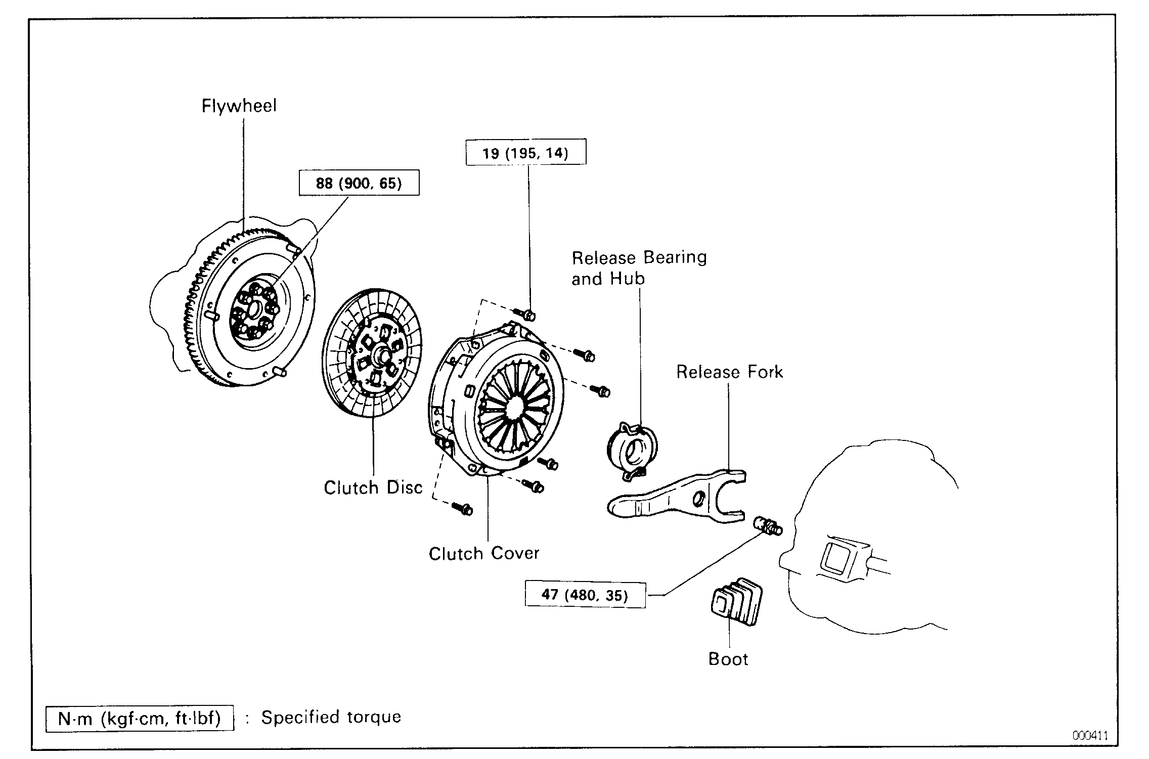
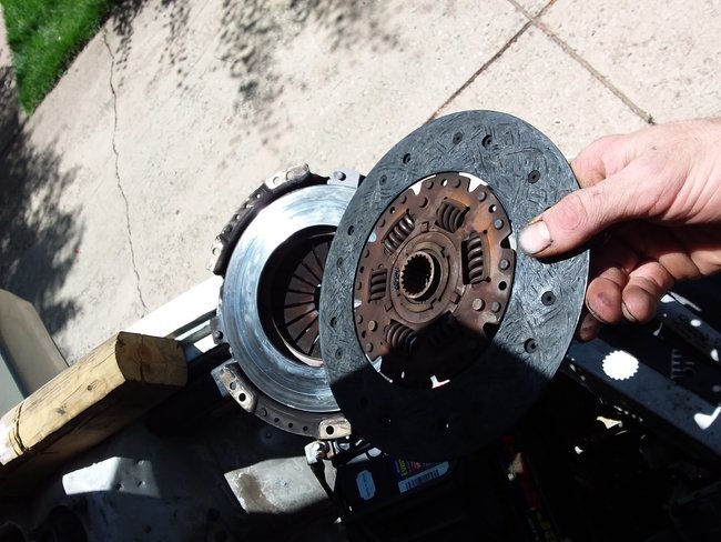
2. REMOVE CLUTCH COVER AND DISC
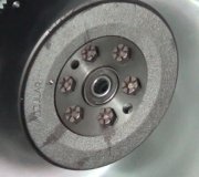
(a)Place matchmarks on the flywheel and clutch cover.
(b)Loosen each set bolt one turn at a time until spring tension is released.
(c)Remove the set bolts, and pull off the clutch cover with the clutch disc.
NOTICE: Do not drop the clutch disc.
Pic 65
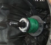
3. REMOVE RELEASE BEARING AND FORK FROM TRANSAXLE
(a)Remove the release bearing together with the fork and then separate them.
(b)Remove the boot.
_________________________________________________
CLUTCH UNIT INSTALLATION
pic 66
CLUTCH UNIT INSTALLATION
1. INSTALL CLUTCH DISC AND CLUTCH COVER ON FLYWHEEL
(a)Insert the SST in the clutch disc, and then set them and the clutch cover in position.
SST 09301-00220
pic 67
(b)Align the matchmarks on the clutch cover and flywheel.
(c)Temporarily tighten the topmost bolt from the three near the knock pins.
HINT: Temporarily tighten the No.3 bolt.
(d)Torque the bolts on the clutch cover in the order shown.
Torque: 19 N.M (195 kgf. Cm, 14 ft. Lbf)
pic 68
2. CHECK DIAPHRAGM SPRING TIP ALIGNMENT
Using a dial indicator with roller instrument, check the diaphragm spring tip alignment.
Maximum non-alignment:
0.5 mm (0.020 in.)
pic 69
If alignment is not as specified, using SST, adjust the diaphragm spring tip alignment.
SST 09333-00013
pic 70
3. APPLY MOLYBDENUM DISULPHIDE LITHIUM BASE GREASE (NLGI NO.2) TO FOLLOWING PARTS
Release fork and hub contact point
Release fork and push rod contact point
Release fork pivot point
Clutch disc spline
pic 71
4. INSTALL RELEASE BEARING AND FORK TO TRANSAXLE
Install the bearing to the release fork, and then install them to the transaxle.
Pic 72
5. INSTALL TRANSAXLE TO ENGINE
____________________________________________________________________
CLUTCH SYSTEM BLEEDING
HINT: If any work is done on the clutch system or if air is suspected in the clutch lines, bleed the system of air.
NOTICE: Do not let brake fluid remain on a painted surface. Wash it off immediately.
1. FILL CLUTCH RESERVOIR WITH BRAKE FLUID Check the reservoir frequently. Add fluid if necessary.
2. CONNECT VINYL TUBE TO BLEEDER PLUG Insert the other end of the tube in a half-full container of brake fluid.
3. BLEED CLUTCH LINE
pic 73
- Slowly pump the clutch pedal several times.
- While pressing on the pedal, loosen the bleeder plug until the fluid starts to run out. Then close the bleeder plug.
- Repeat this procedure until there are no more air bubbles in the fluid.
______________________________________________________________________
Let me know if this helps or if you have other questions.
Take care,
Joe
Images (Click to make bigger)
SPONSORED LINKS
Sunday, May 26th, 2019 AT 9:57 PM