Intermittent no crank

Tiny
BLESSING EWOBOR
  • MEMBER
  • 2010 FORD FOCUS
  • 4 CYL
  • 2WD
  • AUTOMATIC
  • 128,546 MILES
Good evening, the engine won't crank at all sometimes, I have checked the fuse and relay, they are okay, if it starts sometimes the vehicle will be hesitating while accelerating. I scanned it and the code found are shown below. Could any of the codes be the cause?
Wednesday, December 30th, 2020 AT 11:48 AM

17 Replies

Tiny
KASEKENNY
  • MECHANIC
  • 18,907 POSTS
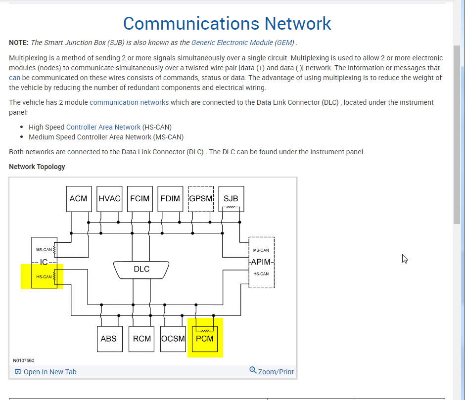
Lots of info here so stick with me as these are not that easy.

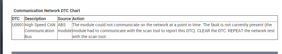
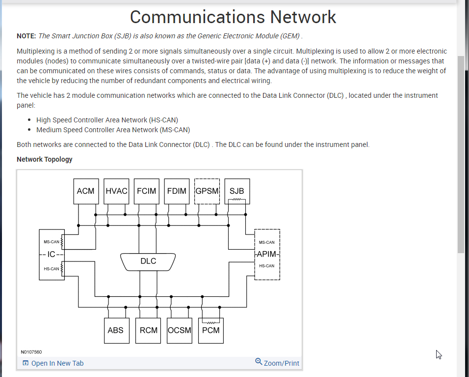
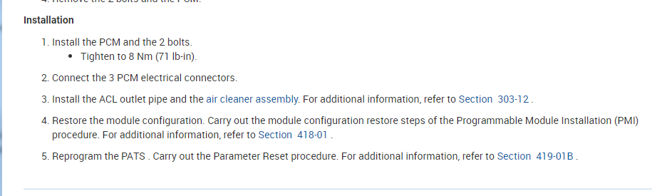
This is a CAN bus issue. Are you familiar with this system? If not, let's start there.

Below is attached a lot of information on all this to get us started.

Also, here is a guide that will help as well:

https://www.2carpros.com/articles/can-scan-controller-area-network-easy

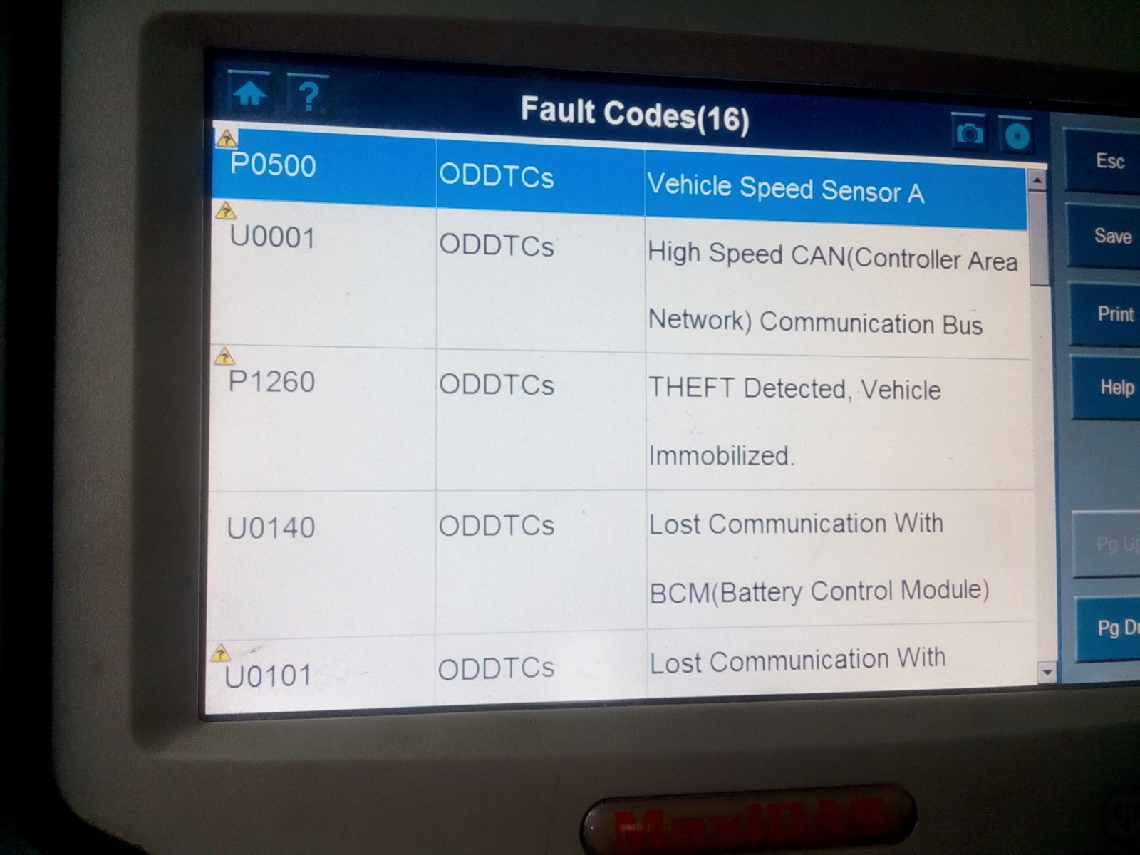
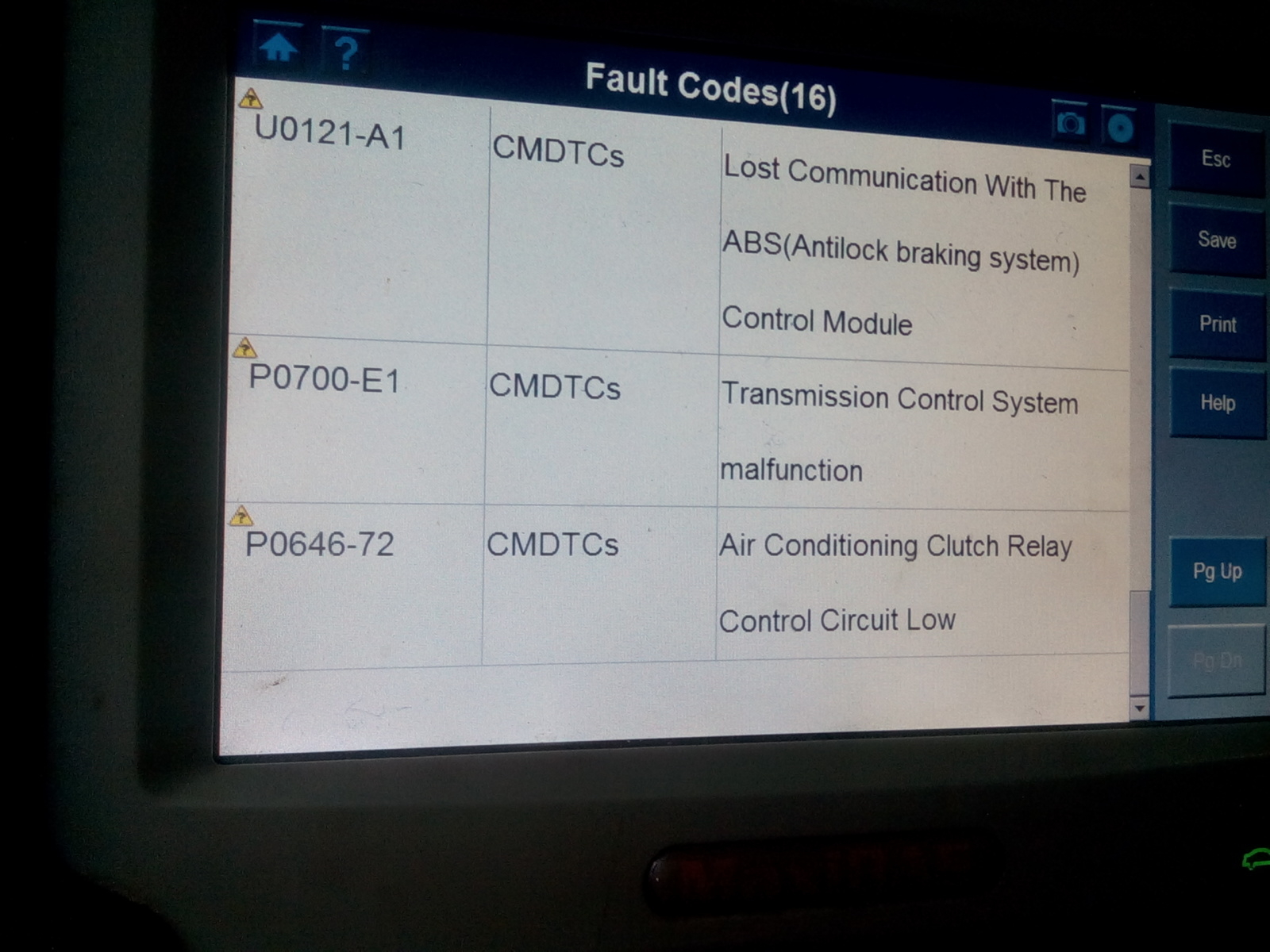
Once we read through this material, does the vehicle start with the scan tool connected to the vehicle? Also, can you go into each module with the scan tool and monitor the data or communicate with it?

Lastly, how often does this happen? Are you able to get it to act up repeatedly? I am concerned we have multiple issues as the theft system code may be causing the no crank and the other codes are causing the running issues. However, the CAN codes may be causing all of it.

Is there a history to this or did this just start one day? Once we get through all this we will need to check the voltage readings at the DLC.

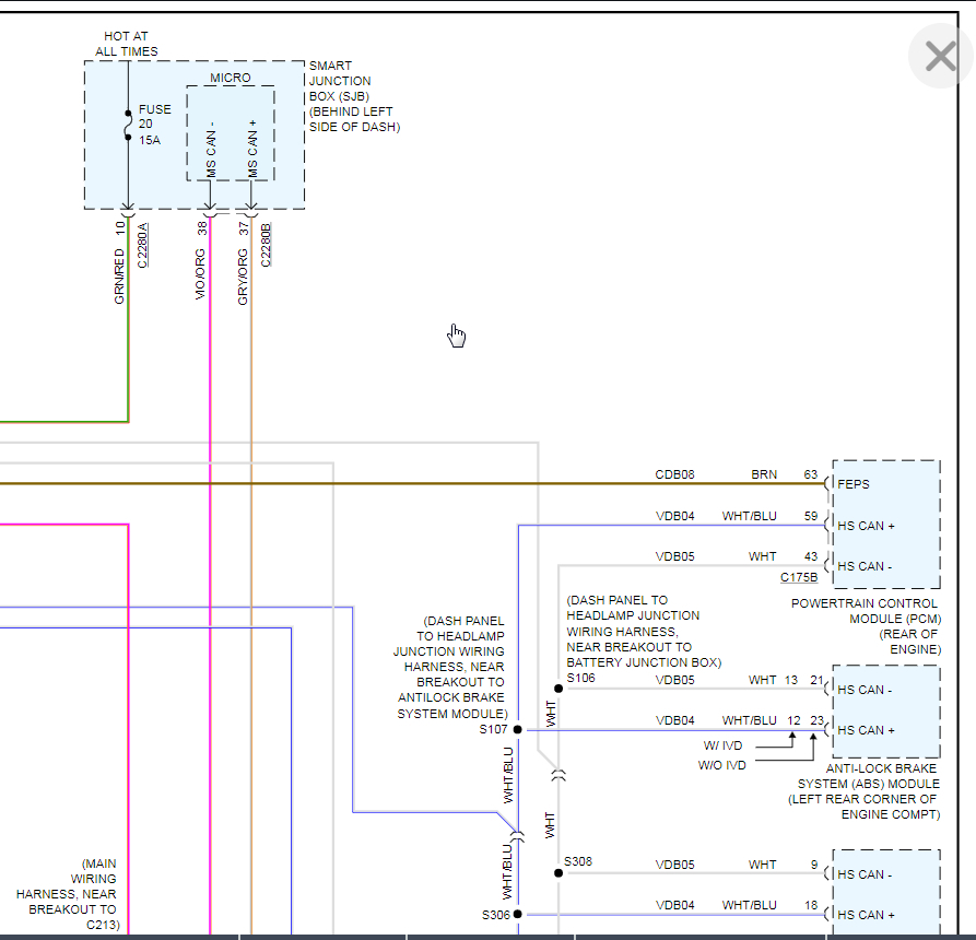
The last page below is a wiring diagram. Please let me know what the voltage is at pin 14 and ground, then 6 and ground.

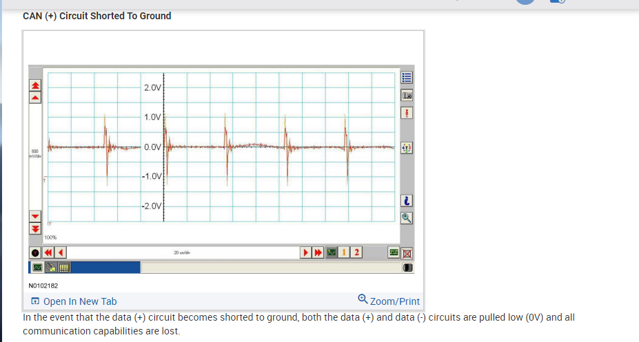
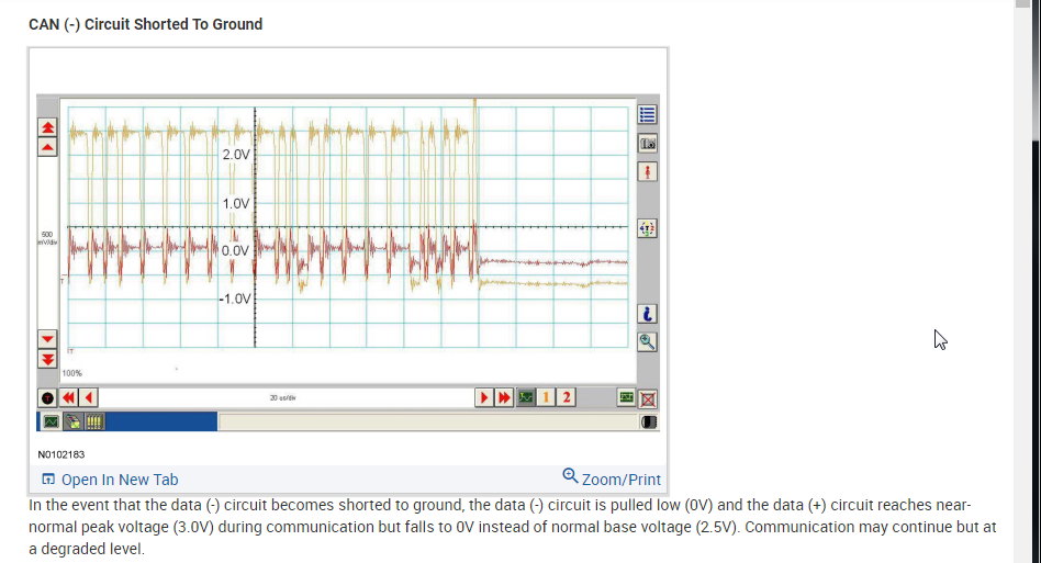
Also, I attached screen shots of what a bus pattern looks like when it has an issue. This is used if you have a scope to monitor the pattern. If you do not then we will try to find this with a meter. Let me know if you have a scope.

Thanks
Was this
answer
helpful?
Yes
No
+1
Friday, January 1st, 2021 AT 8:47 AM
Tiny
BLESSING EWOBOR
  • MEMBER
  • 663 POSTS
Good morning sir, thank you very much.
Was this
answer
helpful?
Yes
No
Friday, January 29th, 2021 AT 11:45 PM
Tiny
BLESSING EWOBOR
  • MEMBER
  • 663 POSTS
I will test for the voltage at the port as soon as possible and I will let you know. For the scope, I don't have for now.
Was this
answer
helpful?
Yes
No
Friday, January 29th, 2021 AT 11:47 PM
Tiny
BLESSING EWOBOR
  • MEMBER
  • 663 POSTS
I don't know if you can help me with a diagram showing the CAN+ and CAN- for the transmission, Powertrain, ABS and instrument cluster.
Was this
answer
helpful?
Yes
No
Saturday, January 30th, 2021 AT 2:04 AM
Tiny
BLESSING EWOBOR
  • MEMBER
  • 663 POSTS
For the scope, it is advisable for someone to use one channel for the analysis?
Was this
answer
helpful?
Yes
No
Saturday, January 30th, 2021 AT 2:06 AM
Tiny
KASEKENNY
  • MECHANIC
  • 18,907 POSTS
I attached the diagrams below that you requested.

As for the scope, it depends on what scope you get. If you have a two channel scope then it is easier to monitor the entire bus since you have a + and - line on the vehicle.

The reason is you could have an issue on only one of the channels so looking at both of them at the same time is a little easier. Plus the lines work together so making sure the patterns exactly mirror each other is helpful.

I also attached a known good pattern of a 5 volt network like this.

You will see that number 1 is pointing to the baseline or average of the two channels. This is 2.5 volts. So if you add the voltages together, they should always equal 5 volts. More then likely you will see the high average at 2.7 and the low at 2.3.

So put one channel on pin 6 and the other on 14.
Was this
answer
helpful?
Yes
No
Saturday, January 30th, 2021 AT 6:30 AM
Tiny
BLESSING EWOBOR
  • MEMBER
  • 663 POSTS
Okay, thank you.
Was this
answer
helpful?
Yes
No
Saturday, January 30th, 2021 AT 10:14 AM
Tiny
BLESSING EWOBOR
  • MEMBER
  • 663 POSTS
Checking the voltage, I found 2.7 volts at can+ and 2.3 volts at can-.
Was this
answer
helpful?
Yes
No
Monday, February 1st, 2021 AT 5:31 AM
Tiny
KASEKENNY
  • MECHANIC
  • 18,907 POSTS
Okay. That is perfect. Was the vehicle operating properly when this was happening? If so, we are going to have to rerun that when it acts up.

That is the problem and worst thing about trying to figure out these CAN issues is you have to have the issue present or it will all check out normal.
Was this
answer
helpful?
Yes
No
Monday, February 1st, 2021 AT 8:01 PM
Tiny
BLESSING EWOBOR
  • MEMBER
  • 663 POSTS
When I checked the resistors, it was moving from 100 ohms to 130 ohms.
Was this
answer
helpful?
Yes
No
Monday, February 1st, 2021 AT 8:14 PM
Tiny
KASEKENNY
  • MECHANIC
  • 18,907 POSTS
Just to confirm you were checking your termination resistance? So you have the battery unhooked and checking resistance from the CAN high to low?

If this is the case then you have a termination issue as it should be 60 ohms consistently.

I was not sure about this but the scan tool says you have loss of communication with the ABS, TCM, and BCM. So if you look the BCM is the battery control module which on this vehicle would be the SJB. That is a terminating resistor on the interior network but that would not affect the ABS. However, the cluster is a terminating resistor for both the HS and interior network so I would think we have an issue with that.

Unplug the cluster completely and see what the termination resistance goes to. It should be a steady 120 ohms. If it does then plug it back in and unplug the PCM and see what it does.
Was this
answer
helpful?
Yes
No
Tuesday, February 2nd, 2021 AT 6:14 PM
Tiny
BLESSING EWOBOR
  • MEMBER
  • 663 POSTS
Thank you.
Was this
answer
helpful?
Yes
No
Tuesday, February 2nd, 2021 AT 8:48 PM
Tiny
BLESSING EWOBOR
  • MEMBER
  • 663 POSTS
The instrument cluster had been replaced when the problem first started.
Was this
answer
helpful?
Yes
No
Tuesday, February 2nd, 2021 AT 8:49 PM
Tiny
KASEKENNY
  • MECHANIC
  • 18,907 POSTS
Interesting. If the cluster has been replaced then you should be able to unplug the PCM while monitoring the termination resistance and it should go to 120 ohms and stay steady. That will show the terminating resistor in the PCM is faulty.
Was this
answer
helpful?
Yes
No
Wednesday, February 3rd, 2021 AT 6:25 PM
Tiny
BLESSING EWOBOR
  • MEMBER
  • 663 POSTS
Where is the PCM located?
Was this
answer
helpful?
Yes
No
Wednesday, February 3rd, 2021 AT 8:33 PM
Tiny
KASEKENNY
  • MECHANIC
  • 18,907 POSTS
It is in the engine bay under the air cleaner assembly. I attached the process below for your review.
Was this
answer
helpful?
Yes
No
Thursday, February 4th, 2021 AT 4:07 PM
Tiny
BLESSING EWOBOR
  • MEMBER
  • 663 POSTS
Thank you very much.
Was this
answer
helpful?
Yes
No
Thursday, February 4th, 2021 AT 8:08 PM

Please login or register to post a reply.

Sponsored links