Hello .. thanks for the donation .. much appreciated
P0771..SSE Functional Failure (Stuck OFF) Mechanical or hydraulic failure of the shift solenoid.
Main Controls
Removal
Remove the fluid pan. For additional information, refer to FLUID PAN, GASKET AND FILTER.
Disconnect the transmission fluid temperature (TFT) sensor electrical connector.
Remove the fluid filter.
NOTE:It is necessary to note the location of the main control wire harness connectors so they can be connected in the same positions. Connector color letters are cast into the solenoid body.
Remove the ground wire bolt. Disconnect the electrical connectors and remove the main control wiring harness.
Solenoid SSC; Color N (Neutral/White).
Solenoid SSE; Color G (Green).
Solenoid SSD; Color L (Blue).
Solenoid EPC; Color B (Black).
Solenoid SSA; Color N (Neutral).
Solenoid SSB; Color B (Black).
NOTE:Note the locations of the 2 long bolts.
Fig. 86: Removing Main Control Valve Body And Accumulators
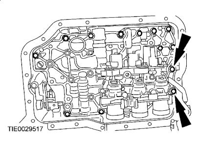
Remove the main control valve body and accumulators.
NOTE:Each accumulator is equipped with 2 springs. All 4 springs are different sizes.
NOTE:Note the size and location of the accumulator springs to aid assembly.
NOTE:Note the shape of each piston and the piston bore from which the piston was removed. The shape and size will vary depending on application. The piston must be installed in its correct bore during assembly.
Remove the accumulator pistons and springs.
Installation
NOTE:The thin longer springs are for the neutral and drive accumulator.
NOTE:Accumulator bore and pistons are matched by depth; some pistons may have steps. Install the pistons in the same bore as removed.
Install the accumulator pistons and springs.
Accumulator 1 and 2.
Accumulator N and D.
CAUTION:Make sure that the manual valve is in the manual control valve shift lever.
NOTE:Do not fully tighten the main control valve bolts at this stage.
Install the main control valve body.
Tighten the main control valve body retaining bolts.
Tighten the bolts in the sequence shown.
Tighten to 9 Nm (80 lb-in).
NOTE:It is necessary to connect the electrical connectors in the same positions as noted in disassembly. Connector color letters are cast into the solenoid body.
Install the main control valve wiring harness, connect the electrical connectors and install the ground wire bolt.
Solenoid SSC; Color N (Neutral/White).
Solenoid SSE; Color G (Green).
Solenoid SSD; Color L (Blue).
Solenoid EPC; Color B (Black).
Solenoid SSA; Color N (Neutral).
Solenoid SSB; Color B (Black).
Tighten to 10 Nm (89 lb-in).
Install the fluid filter.
Connect the TFT sensor electrical connector.
Install the fluid pan. For additional information, refer to FLUID PAN, GASKET AND FILTER.
Hope this helps

SPONSORED LINKS
Wednesday, March 24th, 2010 AT 2:16 AM