Hi,
I'm not sure where to start. This couldn't be a more simple circuit but nothing is matching up with my schematic which is based on your VIN code.
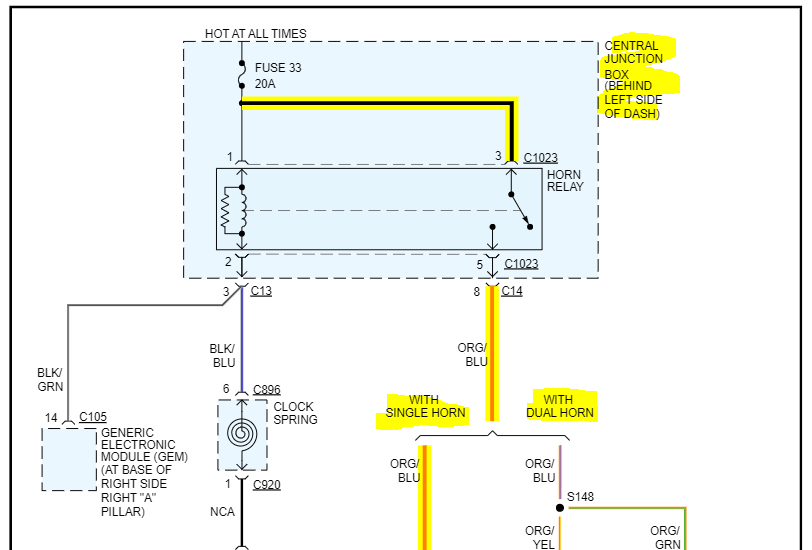
We need to confirm a few things. First, the vehicle may have come with one horn or two. However, the power supply stays the same. The only difference is with two horns, there is a splice from the power supply which branches to two horns.
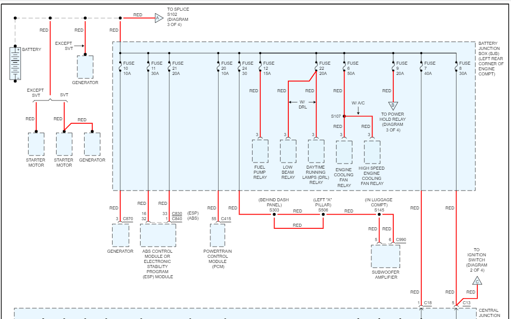
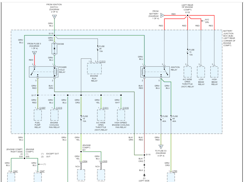
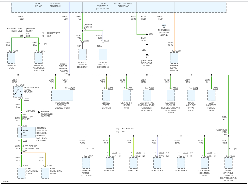
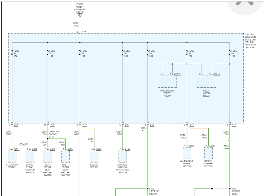
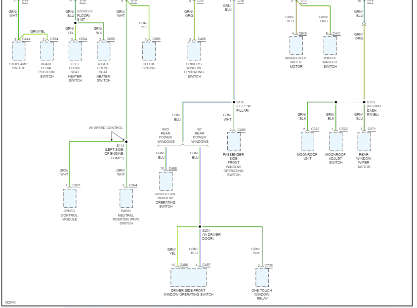
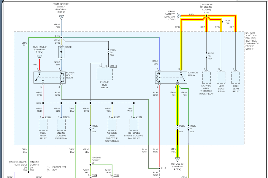
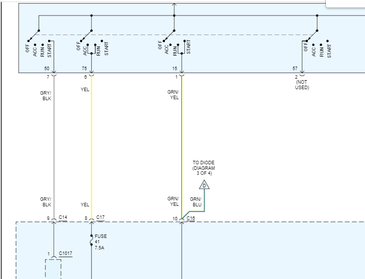
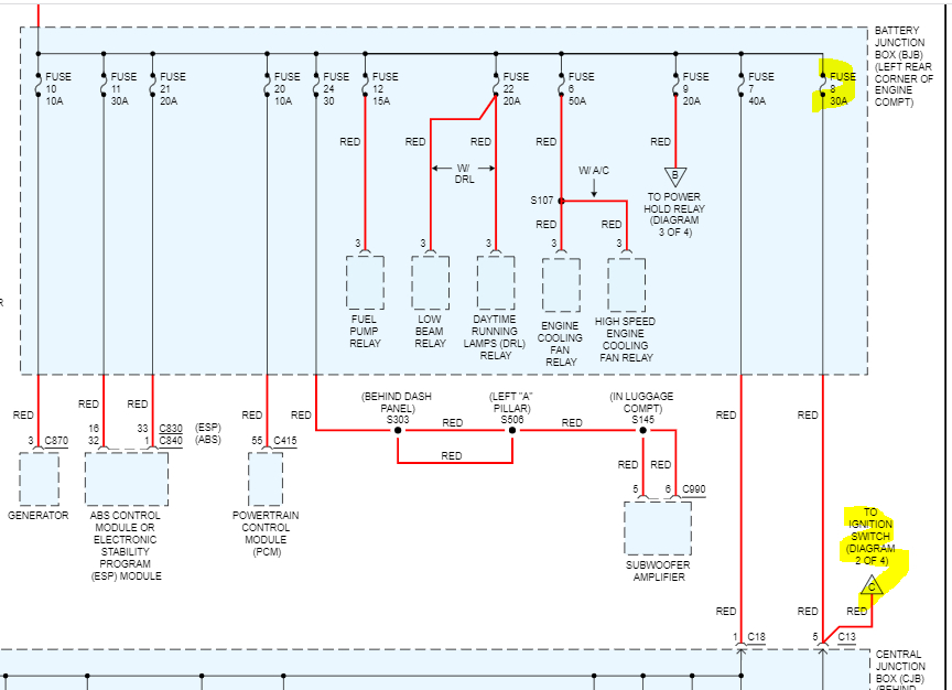
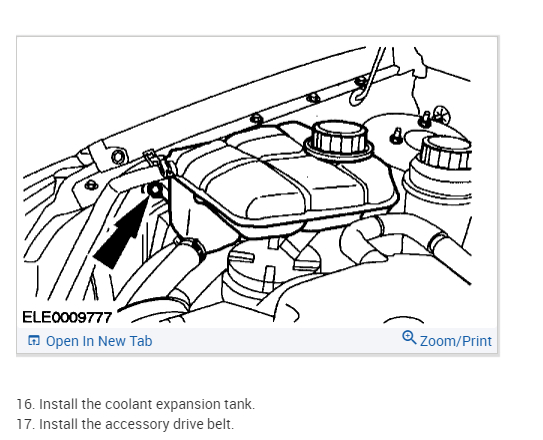
I attached the schematic below for you as a reference.
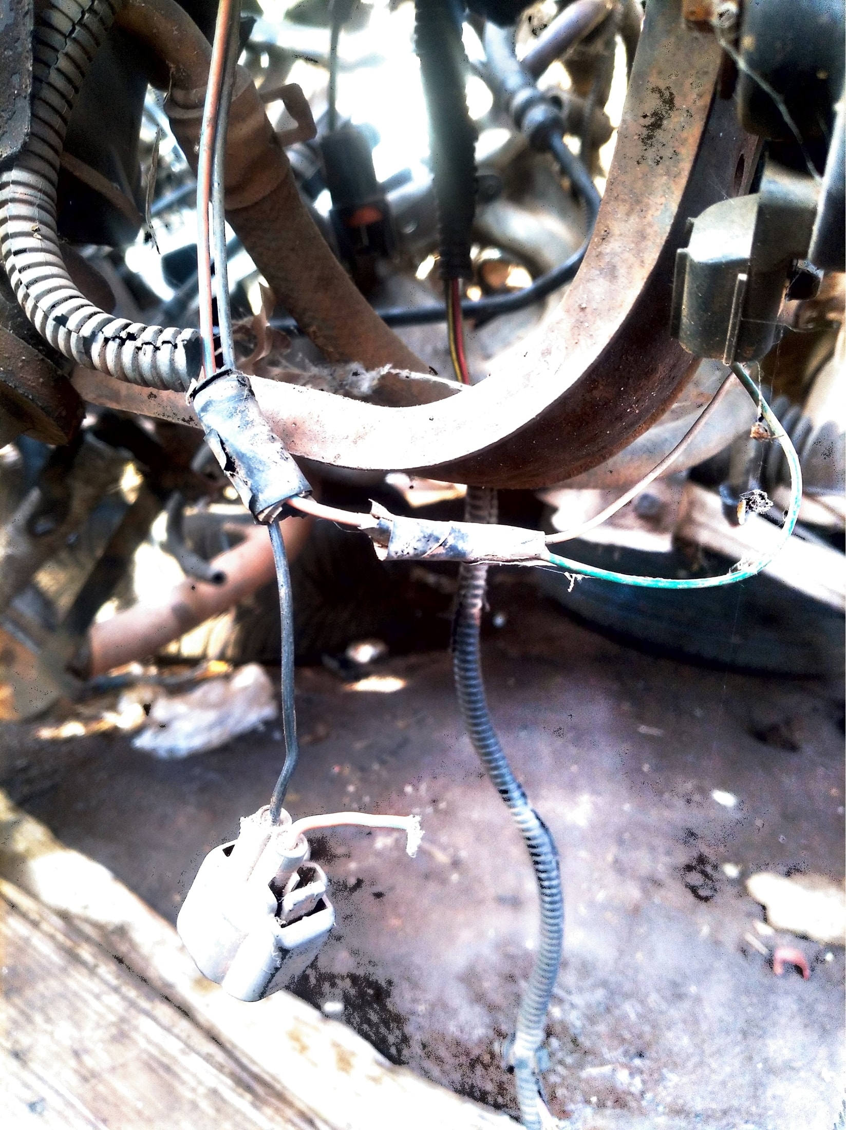
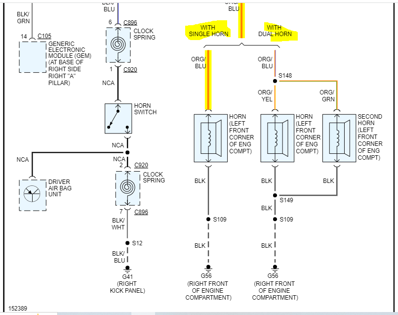
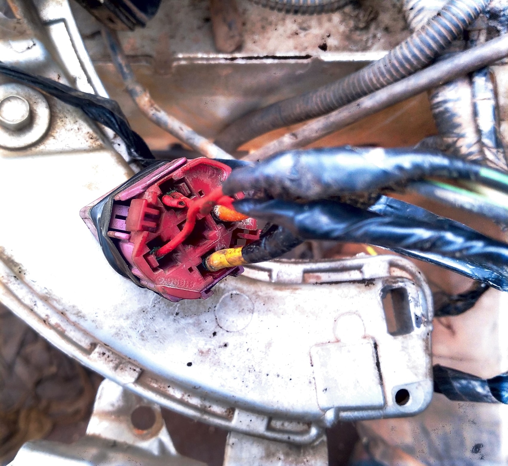
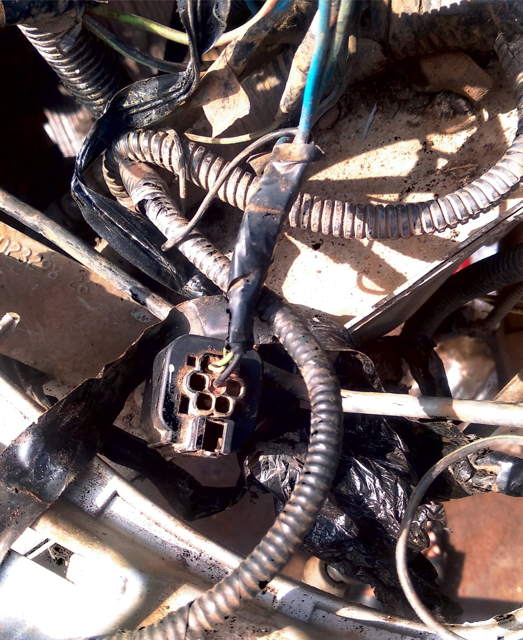
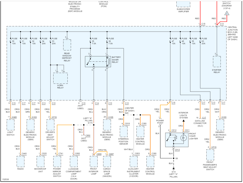
From the horn relay, the power supply should be via an orange wire with a blue tracer. If you have only one horn, power from that wire goes directly to the horn. At the horn connector, there is a black wire that should run to ground at the right front of the engine compartment.
If you have two horns, power is still provided via the orange wire with a blue tracer. However, there is a splice into an orange wire with a yellow tracer. The orange/yellow wires go to the two horns. Again, the black wires splice together and go to ground.
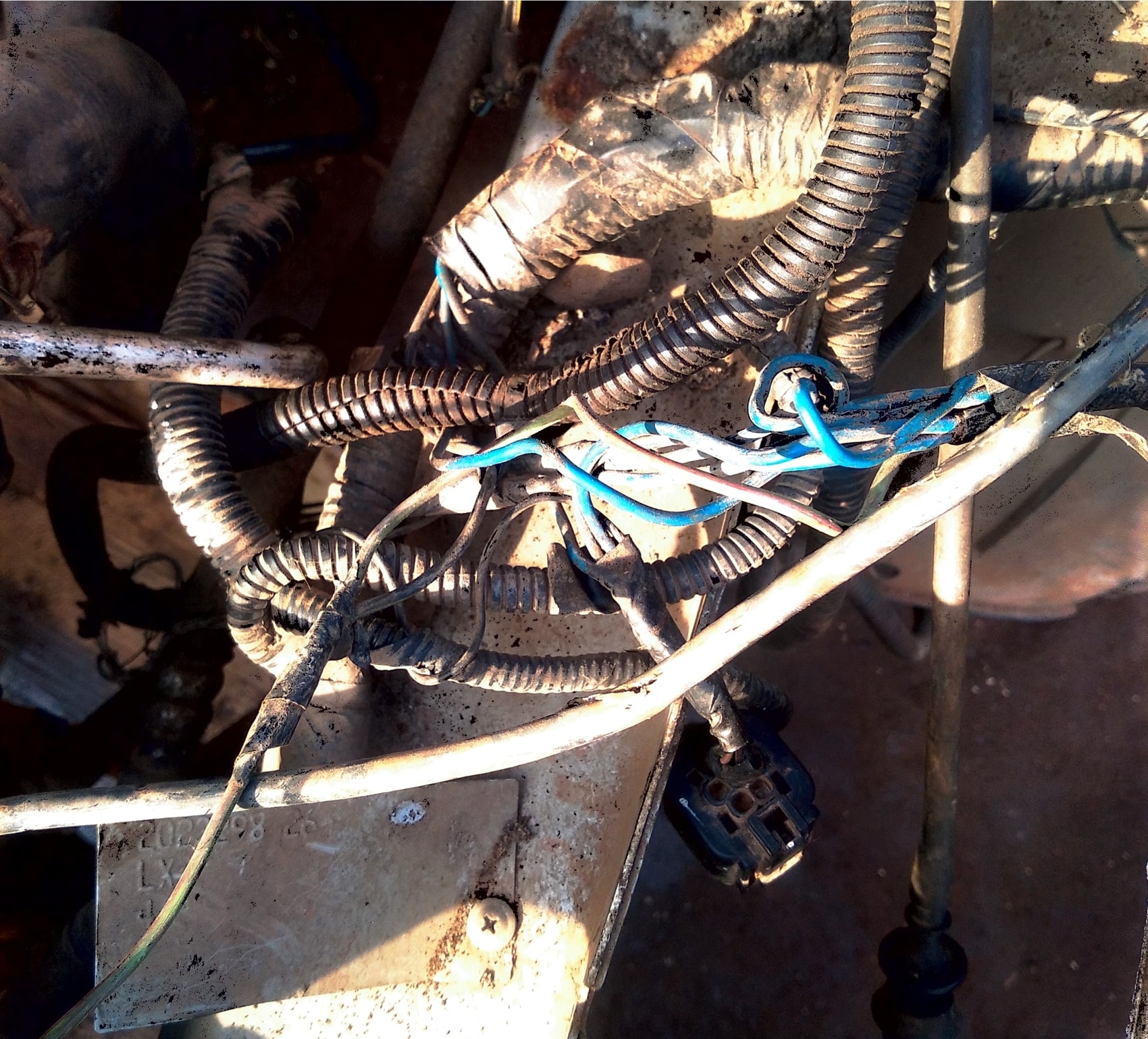
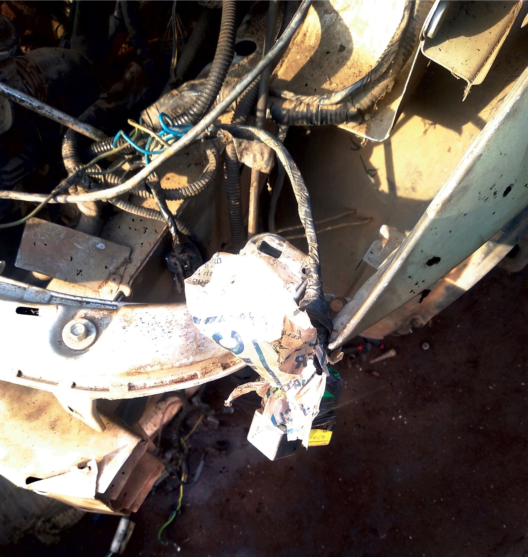
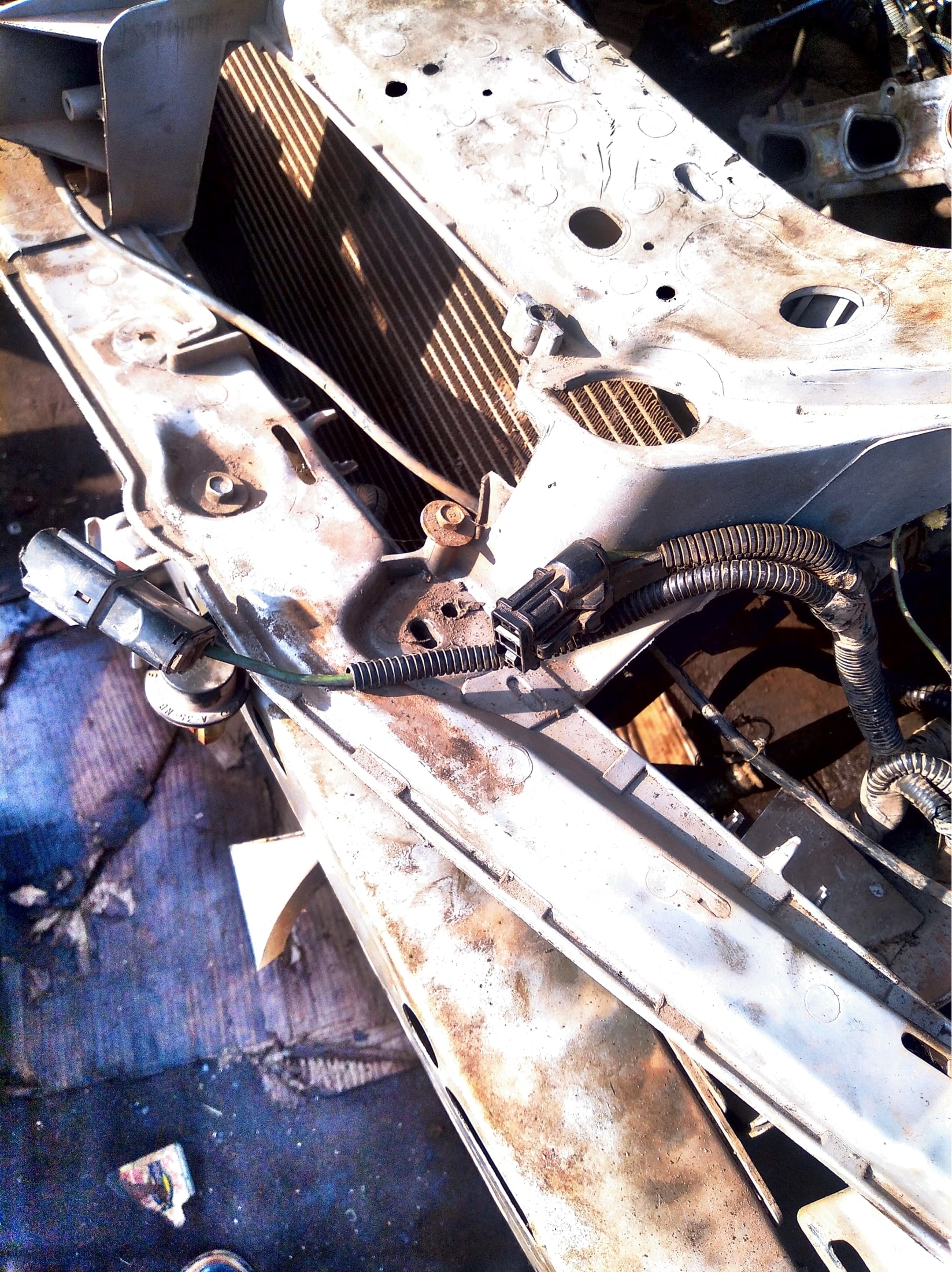
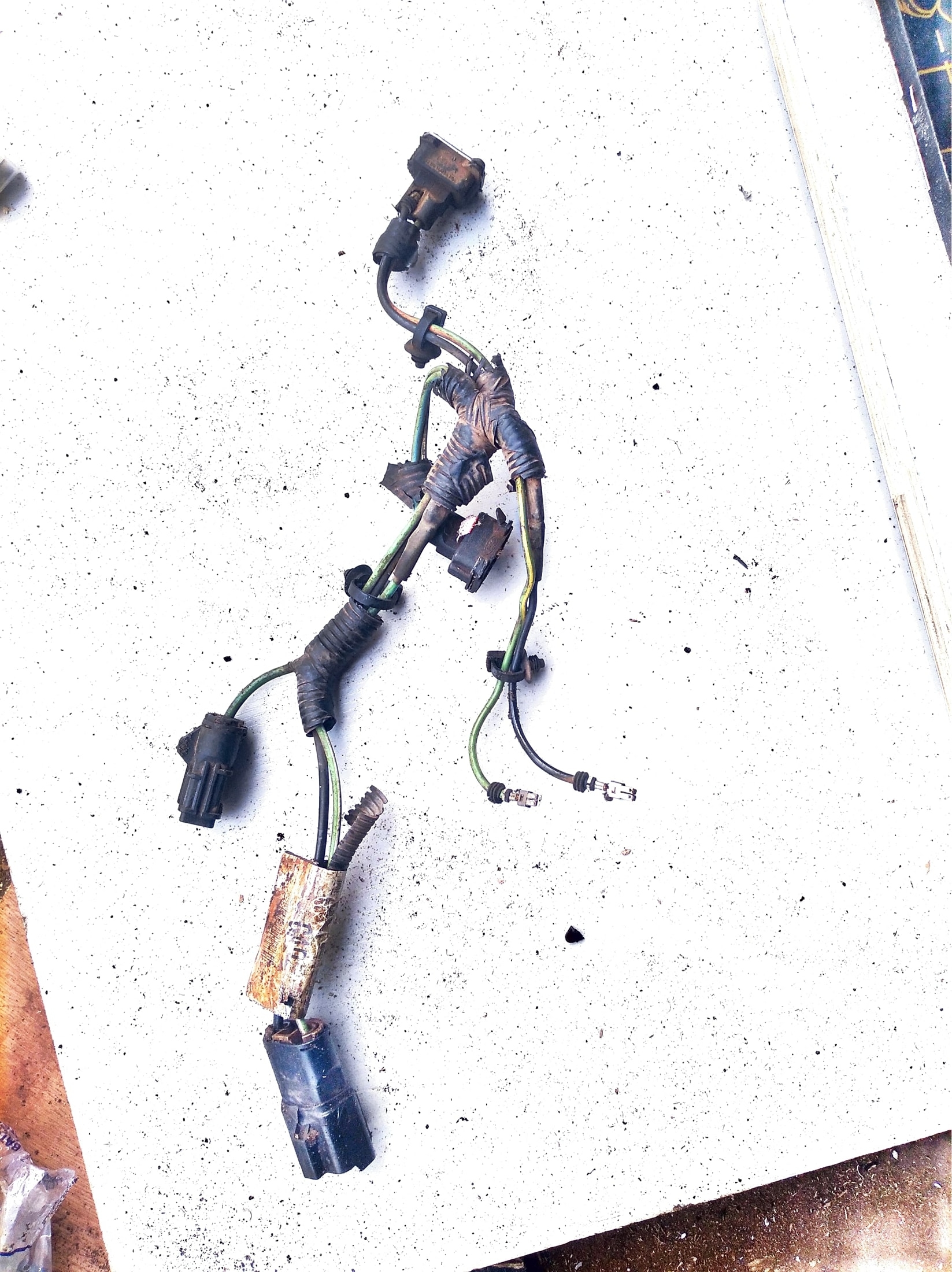
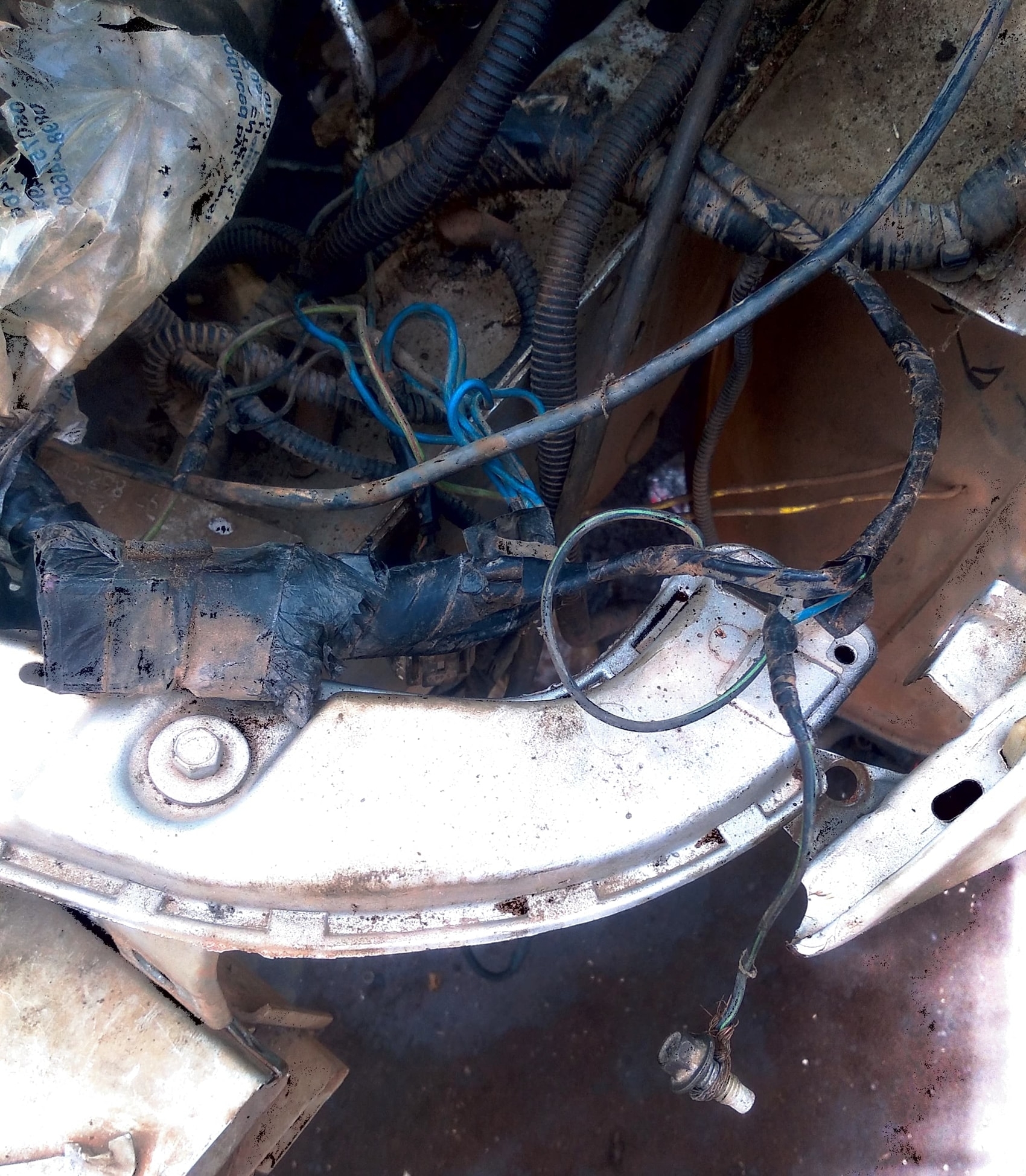
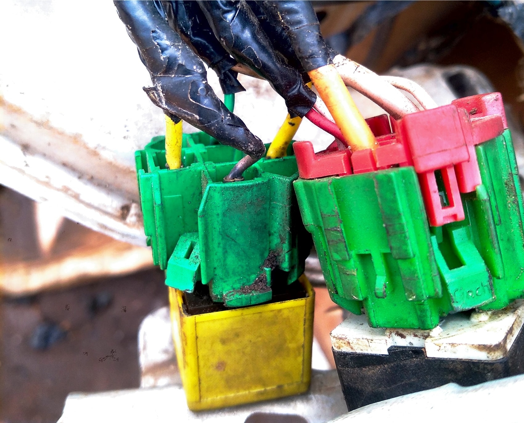
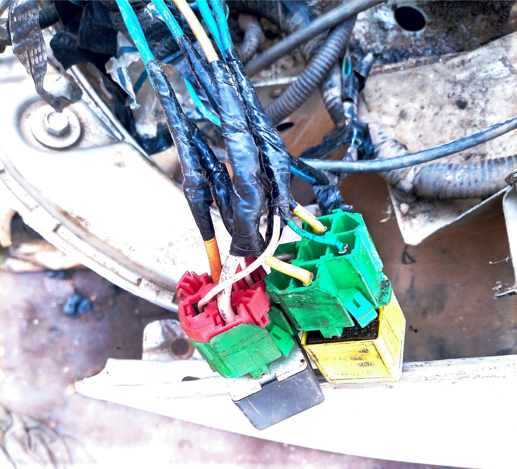
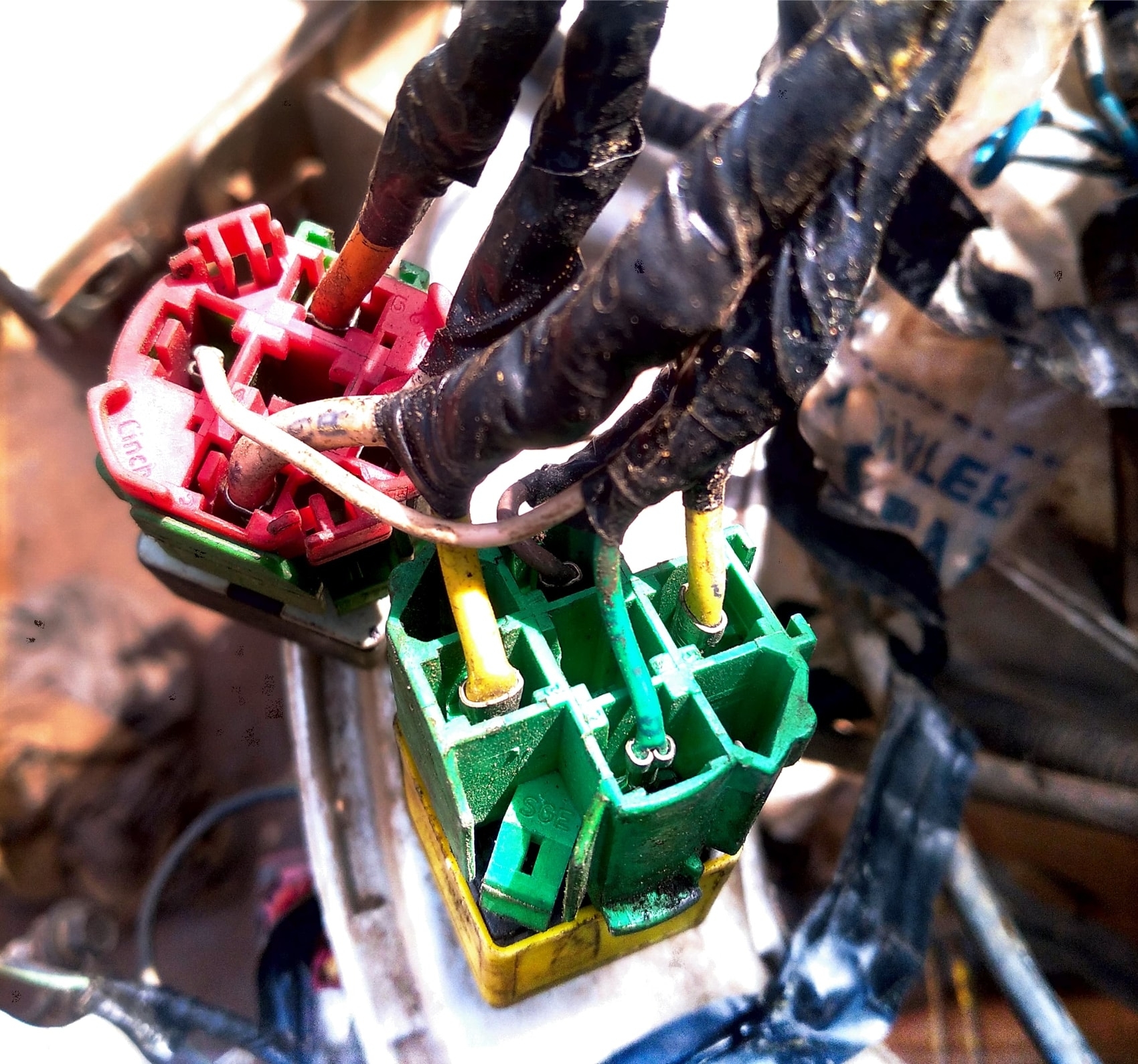
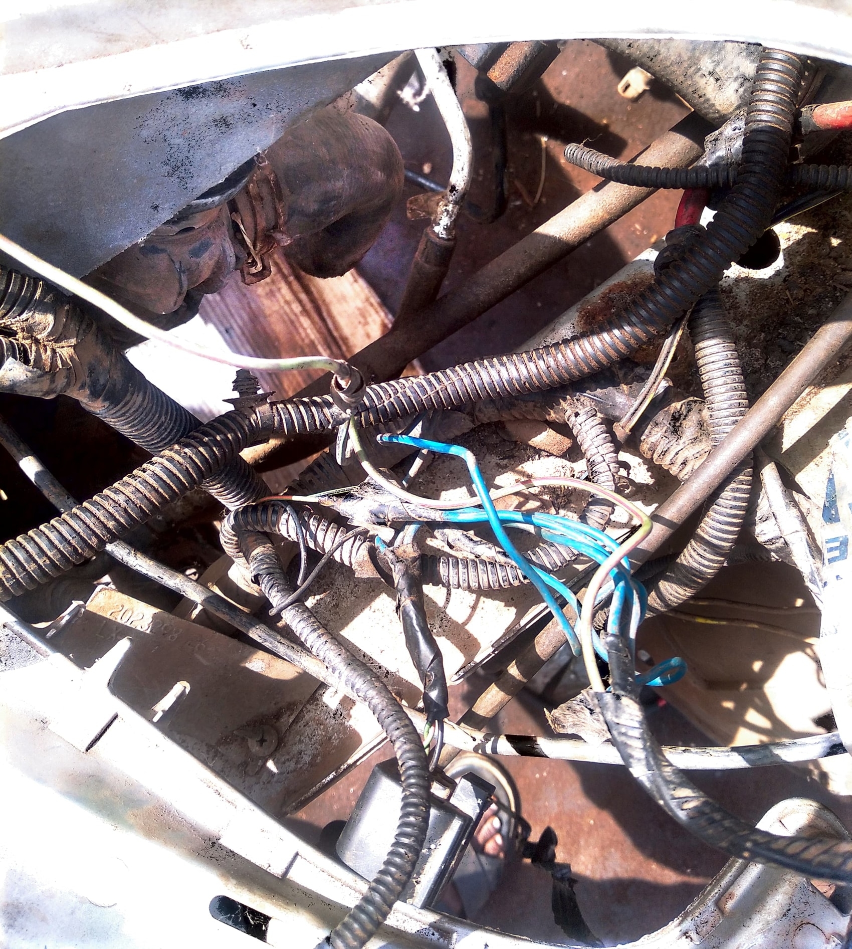
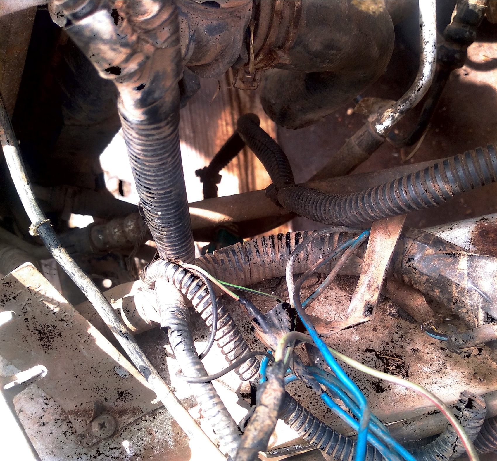
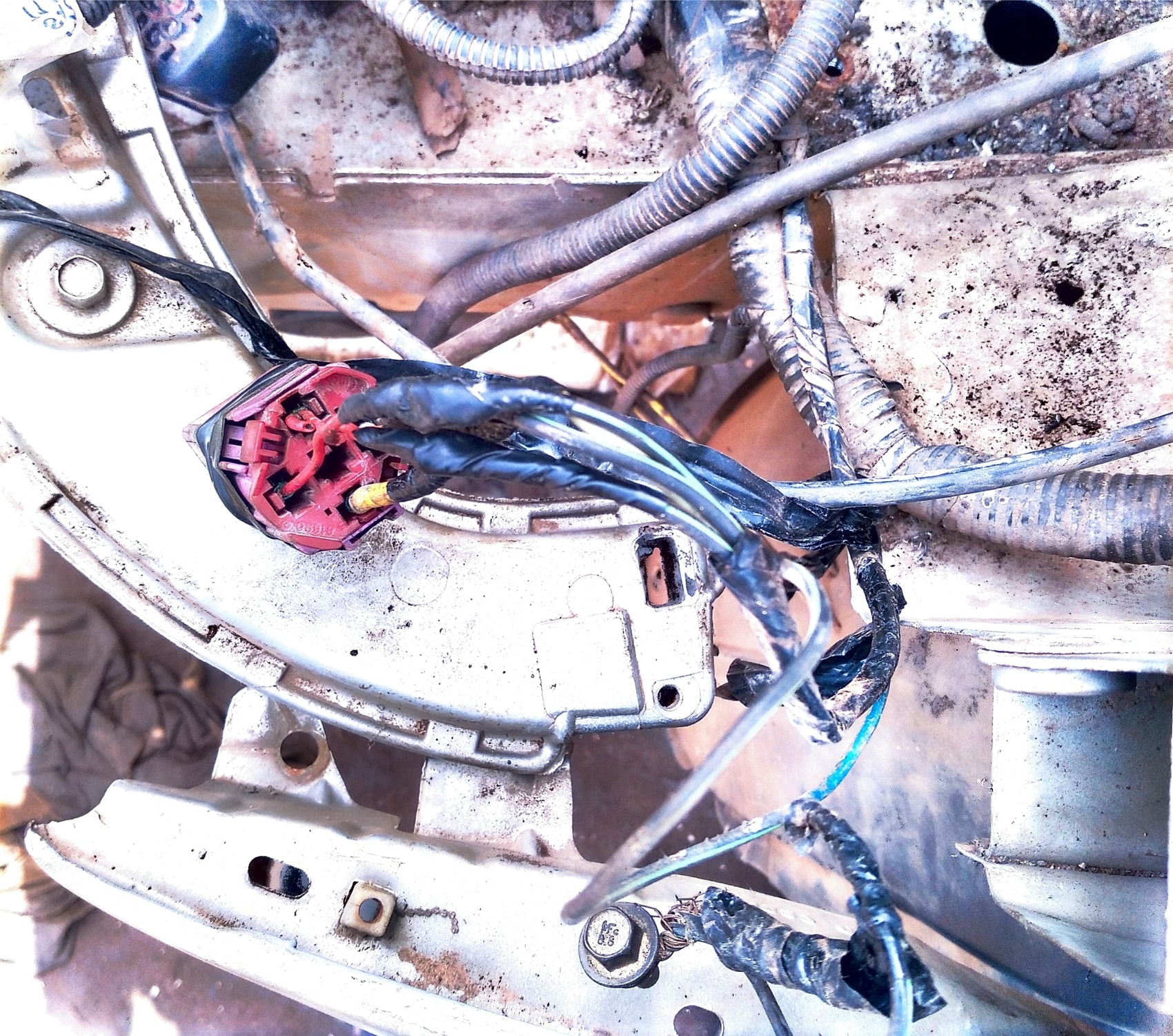
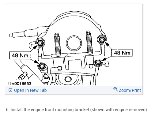
The reason I'm confused is you didn't mention any of the wire colors I mentioned. If you were to clean the wires, can you tell if what I mentioned is present? I'm not sure why, but if appears different wiring was spliced in place of the original wiring and then insulated with electrical tape. When you join wires together, they need to be soldered and heat shrink needs to be placed over the connection for insulation. You can't twist them together and tape them. The connection will eventually fail.
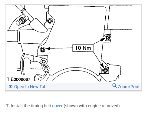
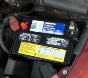
Let me know about the wire colors, and hang in there. We can get it working. I could walk you through doing it and you will do a 100 times better job. It would just require a few tools, a solder gun, and heat shrink. Also, if you have a test light, see if there is power to any of the wires at the horns when a helper presses the horn button.
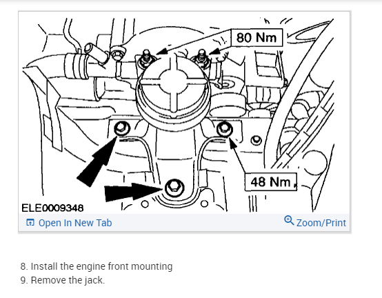
Take care and if I don't hear from you, have a great Christmas.
Joe
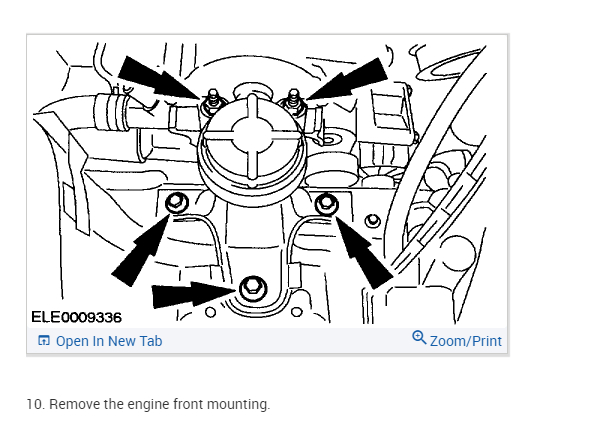
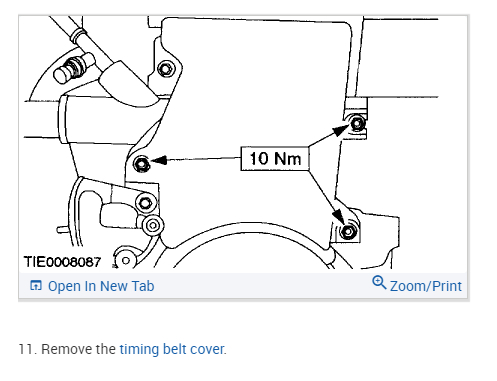
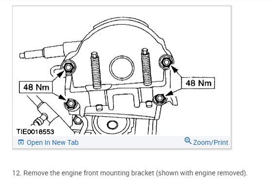
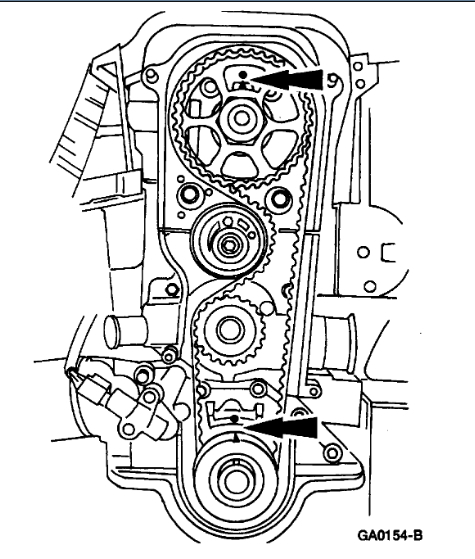
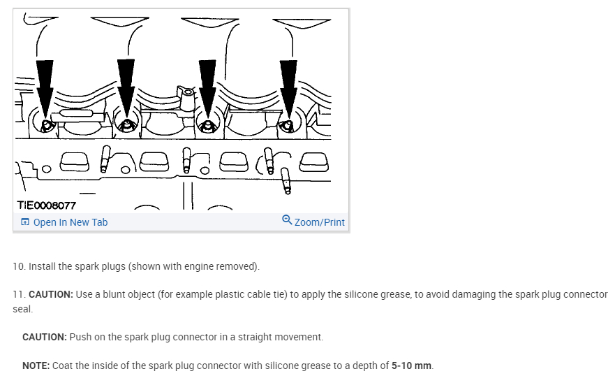
See pics below.
Images (Click to make bigger)
Saturday, December 24th, 2022 AT 12:35 PM