Welcome to 2CarPros.
Honestly, I have a feeling you may be correct. First, lets check for a bad head gasket. Here is a link that shows how it is done:
https://www.2carpros.com/articles/head-gasket-blown-test
Also, if the engine is cold, open the cooling system and start the engine. Does coolant shoot out? If so, you nailed it with the idea that compressed air is getting into the system from a head gasket.
If you find the gasket is bad, here are the directions for replacement. First will be the directions for cylinder head removal, then inspection, and finally instillation. All attached pictures will correlate with these directions.
I am only providing this in case you find the gasket is the issue.
______________________________
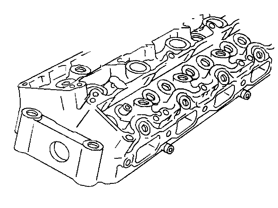
13. CYLINDER HEAD REMOVAL
Tools Required
- J 38188 Cylinder Head Broken Bolt Extractor Kit (if needed)
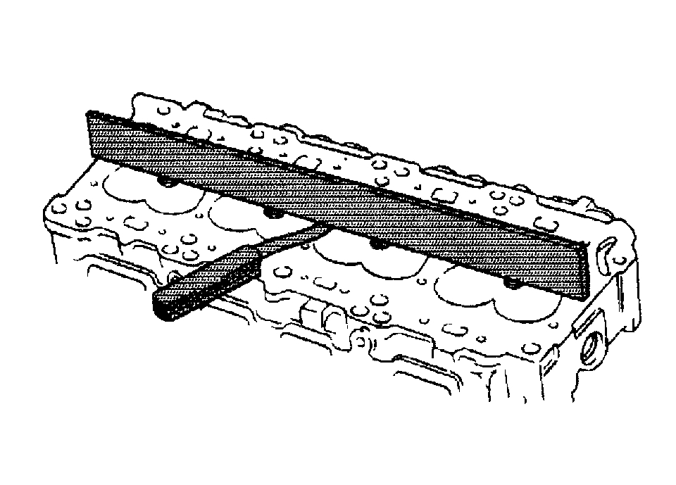
Pic 1
1. Remove the cylinder head to the block bolts. Follow the reverse of the tightening sequence.
2. Remove the cylinder head.
3. Remove the cylinder head gasket.
Notice: Engine damage may result if an abrasive paper, pad, or motorized wire brush is used to clean any engine gasket surfaces.
pic 2
4. Clean all of the gasket surfaces.
5. Use the following procedures when cleaning the cylinder head and cylinder block surfaces:
Important: Be careful not to gouge or scratch the gasket surfaces. Do not gouge or scrape the combustion chamber surfaces. The feel of the gasket surface is important, not the appearance. There will be indentations from the gasket left in the cylinder head after all to the gasket material is removed. These small indentations will be filled in by the new gasket.
Use a razor blade gasket scraper to clean the cylinder head and cylinder block gasket surfaces.
Use a razor blade gasket scraper to clean the cylinder head and cylinder block gasket surfaces. Do not scratch or gouge any surface.
Important: Do not use any other method or technique to clean these gasket surfaces.
Use a new razor blade for each cylinder head and cylinder block.
Hold the razor blade as parallel to the gasket surface as possible.
Important: Do not use a tap to clean the cylinder head bolt holes.
6. Clean the old sealer/lube and dirt from the bolt, the studs, and the bolt holes.
7. Clean the bolt holes using a nylon bristle brush.
Caution: Wear safety glasses to avoid injury when using compressed air or any cleaning solvent. Bodily injury may occur If fumes are inhaled or if skin is exposed to chemicals.
8. When cleaning the cylinder head bolt holes 1 - 8 use a suitable commercial spray liquid solvent and compressed air from an extended-tip blow gun to reach the bottom of the holes.
9. Remove any broken long cylinder head bolts using the J 38188.
_________________________________________
34. CYLINDER HEAD CLEAN AND INSPECT
Valve Cleaning and Inspection
Important: Do not scratch the valve stem with the wire brush.
pic 3
1. Clean the valves of carbon, oil, and varnish. Carbon can be removed with a wire brush. Varnish can be removed by soaking the valves in Parts Immersion Solvent GM P/N 12345368 or an equivalent.
2. Clean the valve guides.
3. Inspect the valve stem for wear. The valve stem end may be reconditioned by grinding.
4. Follow the grinder manufacturer's instructions. Ensure that the new surface is perpendicular to the valve stem.
5. Inspect the valve keeper groove for chipping or wear. Replace the valve if chipped or worn.
6. Inspect the valve face for burning or cracking. If pieces are broken off, inspect the corresponding piston and cylinder head area for damage.
7. Inspect the valve stem for burrs and scratches. Burrs and minor scratches may be removed with an oil stone.
8. Inspect the valve stem for straightness and the valve head for bending or distortion. Use V blocks. Bent or distorted valves must be replaced.
9. Clean the deposits from the valve face. Inspect the valve face for grooving.
10. Replace the valve if the face is grooved. Valve faces cannot be machined. If worn or damaged, the valves must be replaced.
11. The valves may be lightly lapped to the valve seats.
Cylinder Head and Gasket Surface Cleaning and Inspection
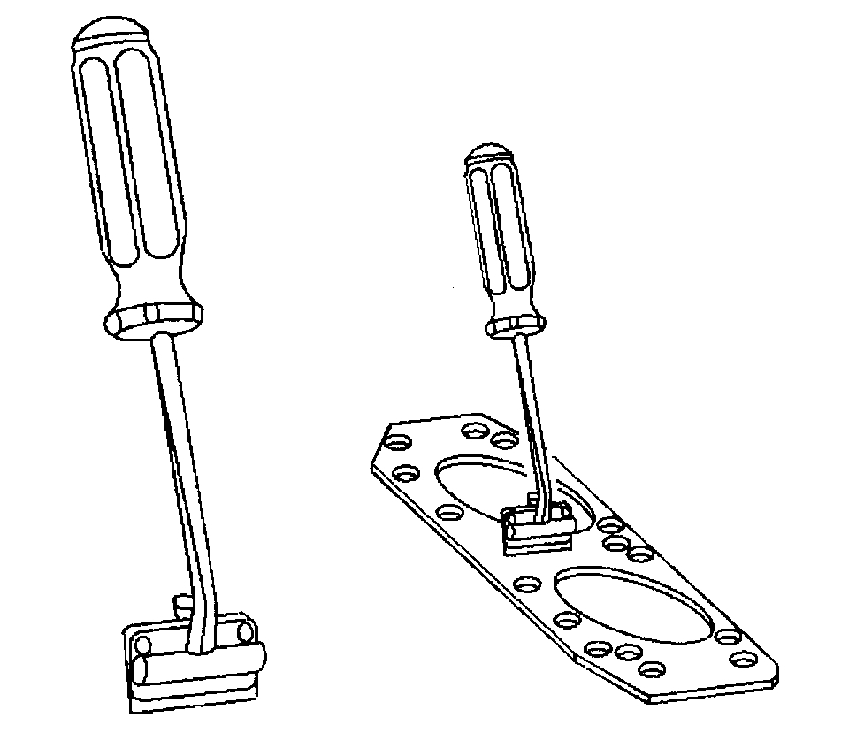
1. Use the following procedure to remove the cylinder head cup plugs:
1.1. Obtain a suitable self-threading screw.
1.2. Drill a hole in the plug.
1.3. Install the self-threading screw.
1.4. Pry out the plug and discard it.
1.5. Remove the spark plugs.
2. Inspect the cylinder head gasket and mating surfaces for leaks, corrosion and blow-by. If the gasket has failed, use the following faults to determine the cause:
Improper installation
Loose or warped cylinder head
Missing, off location or not fully seated dowel pins
Corrosion in the seal area around the coolant passages
Chips or debris in the cylinder head bolt holes
Bolt holes in the cylinder block not drilled or tapped deep enough
Other
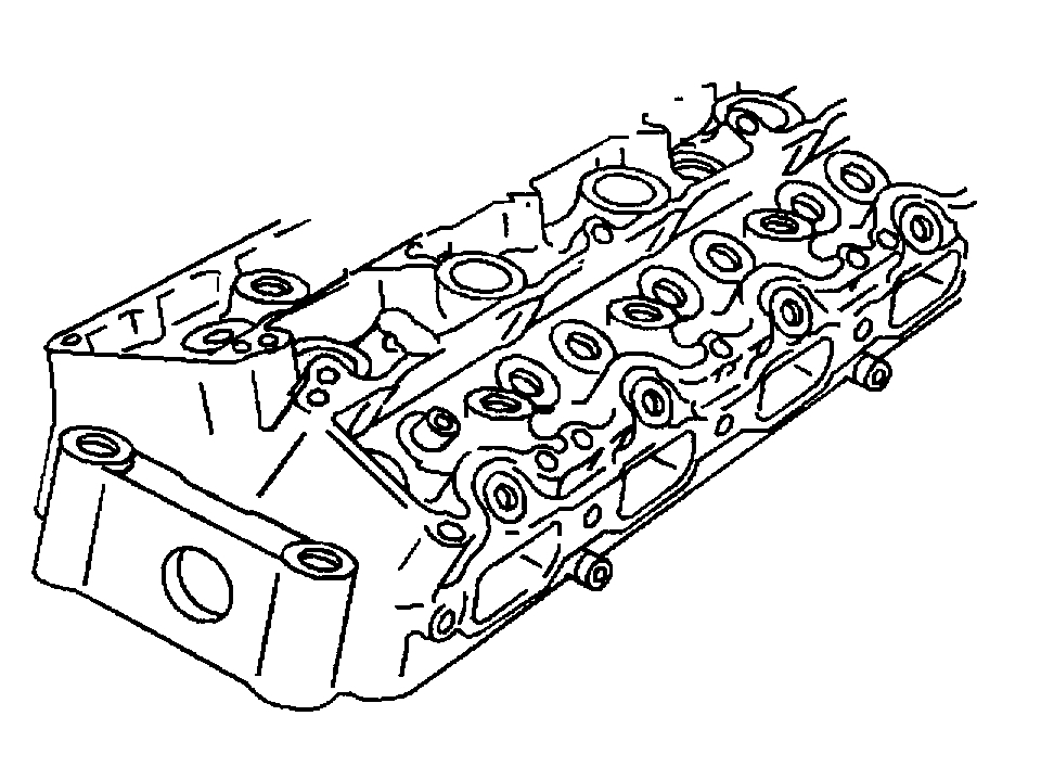
pic 4
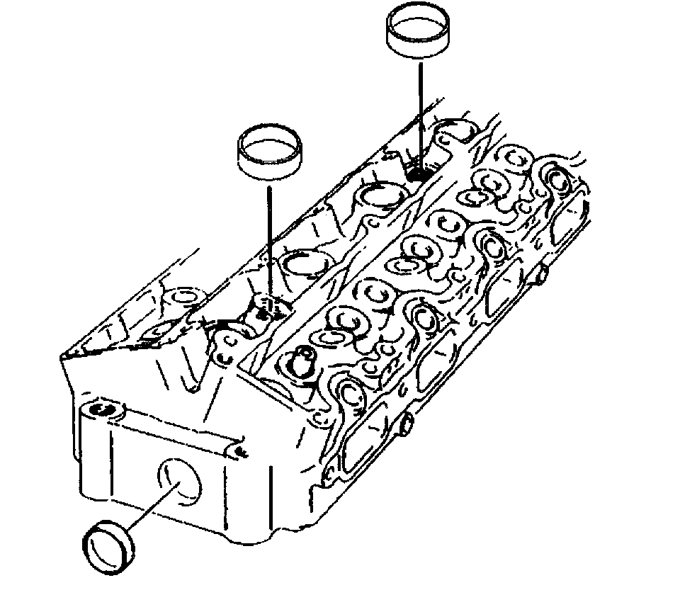
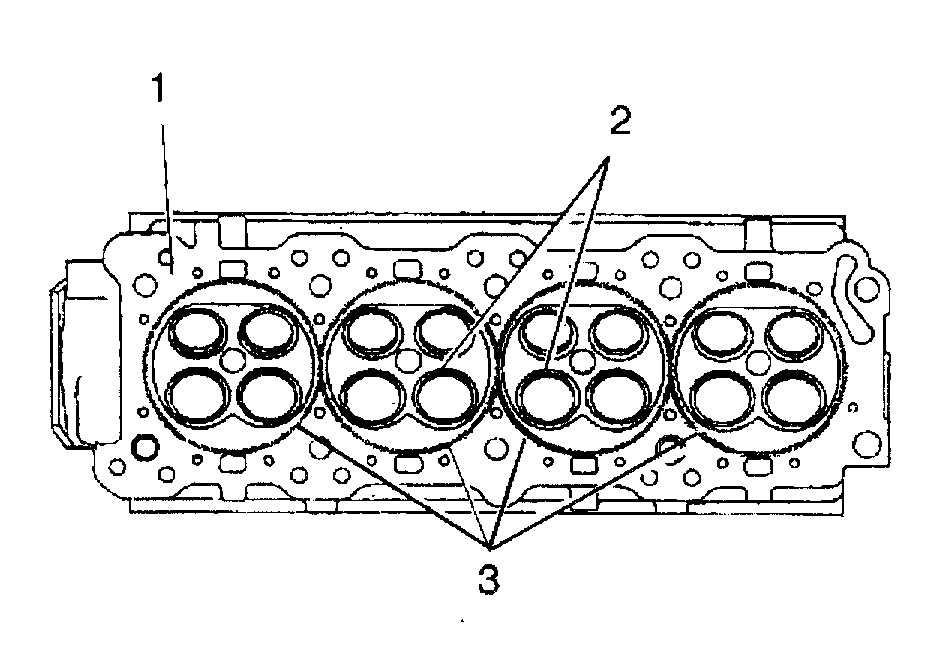
3. Inspect the cylinder head gasket surface.
The cylinder head may be reused if corrosion is found only outside a 4 mm (0.375 inch) band around each combustion chamber (1).
Replace the cylinder head if the area between the valve seats is cracked (2).
Replace the cylinder head if corrosion has been found inside a 4 mm (0.375 inch) band around each combustion chamber (3).
4. Clean the cylinder head bolts.
Important: Do not use a wire brush on any gasket sealing surface.
5. Clean the cylinder head. Remove all varnish, soot and carbon to the bare metal.
6. Clean the valve guides.
7. Clean the threaded holes. Use a nylon bristle brush.
8. Clean the remains of the sealer from the plug holes.
9. Inspect the cylinder head bolts for damaged threads or stretching and damaged heads caused by improper use of tools.
10. Replace all suspect bolts.
Important: Do not attempt to weld the cylinder head. Replace the cylinder head instead.
11. Inspect the cylinder head deck for corrosion, sand inclusions and blow holes.
pic 5
12. Inspect the cylinder head deck, the intake, and exhaust manifold mating surfaces for flatness. These surfaces may be reconditioned by parallel grinding.
13. Use the following steps to determine the amount of reconditioning needed:
If the warpage is less than 0.076 mm (0.003 inch), reuse the cylinder head, but do not resurface.
If the warpage is between 0.076 mm (0.003 inch) and 0.25 mm (0.010 inch), resurface the cylinder head before reusing.
If the warpage is over 0.25 mm (0.010 inch), discard the cylinder head.
14. Inspect all the threaded holes for damage. The threads may be reconditioned with thread inserts.
15. Inspect the sealing surfaces.
16. Inspect the cylinder head cup plugs.
_______________________________________________________
53. CYLINDER HEAD INSTALLATION
Tools Required
- J 36660-A Torque Angle Meter
pic 6
1. Install the cylinder head gasket to the block.
Important: Do not use any sealing material.
2. Install the cylinder head.
3. Lightly apply clean engine oil to the threads and the bottom side of the flange of the head bolt and allow the oil to drain before installing.
Notice: Refer to Fastener Notice in Service Precautions.
pic 7
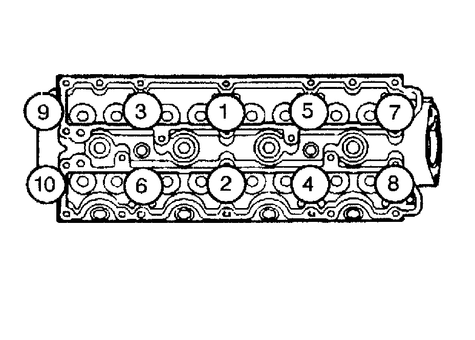
4. Install and tighten the cylinder head bolts in sequence.
Tighten bolts 1-8 to 65 Nm (40 ft. lbs.).
Tighten bolts 9-10 to 40 Nm (30 ft. lbs.).
Then turn all the bolts an additional 90 degrees in sequence, using the J 36660-A.
__________________________________
Here are the directions (which will be needed if the head needs removed) for timing chain removal and replacement. With the mileage on the vehicle, I would recommend replacing the chain, sprockets and tensioner.
_____________________________
2000 Oldsmobile Alero L4-144 2.4L DOHC VIN T SFI
Timing Chain, Sprocket, and Tensioner Replacement
TIMING CHAIN, SPROCKET, AND TENSIONER REPLACEMENT
CAMSHAFT TIMING CHAIN, SPROCKET, AND TENSIONER REPLACEMENT
Tools Required
- J36008-A Camshaft Sprocket Alignment Pins
- J39579 Camshaft Sprocket Wrench
Removal Procedure
Caution: Unless directed otherwise, the ignition and start switch must be in the OFF or LOCK position, and all electrical loads must be OFF before servicing any electrical component. Disconnect the negative battery cable to prevent an electrical spark should a tool or equipment come in contact with an exposed electrical terminal. Failure to follow these precautions may result in personal injury and/or damage to the vehicle or its components.
Notice: The timing chain on the LD9 (VIN T) Twin Cam Engine is not to be replaced with the timing chain from any other model year. The timing sprockets are different on the Twin Cam engine and the shape of the links matches the sprockets. Engine damage may result if the wrong timing chain is used. The timing chain and the crankshaft sprocket must be marked so that they are reinstalled in the same side facing out at the time of reassembly.
1. Disconnect the negative battery cable.
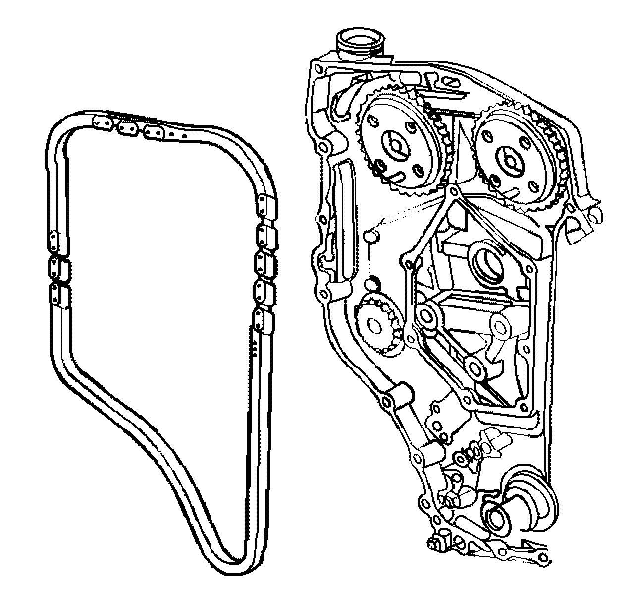
2. Remove the engine front cover. See: Timing Cover > Procedures > Engine Front Cover Replacement
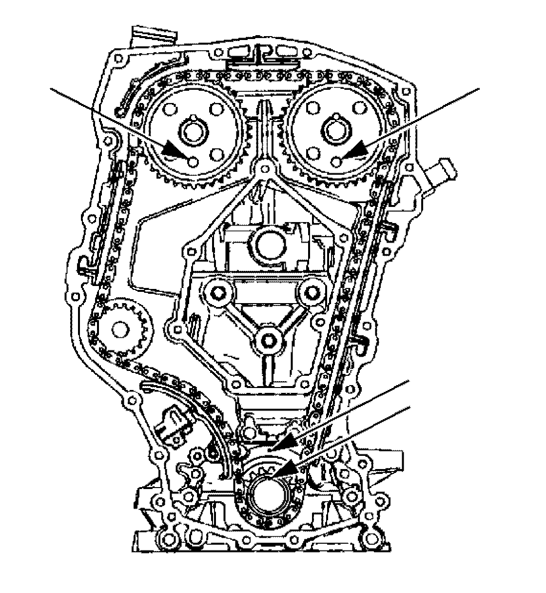
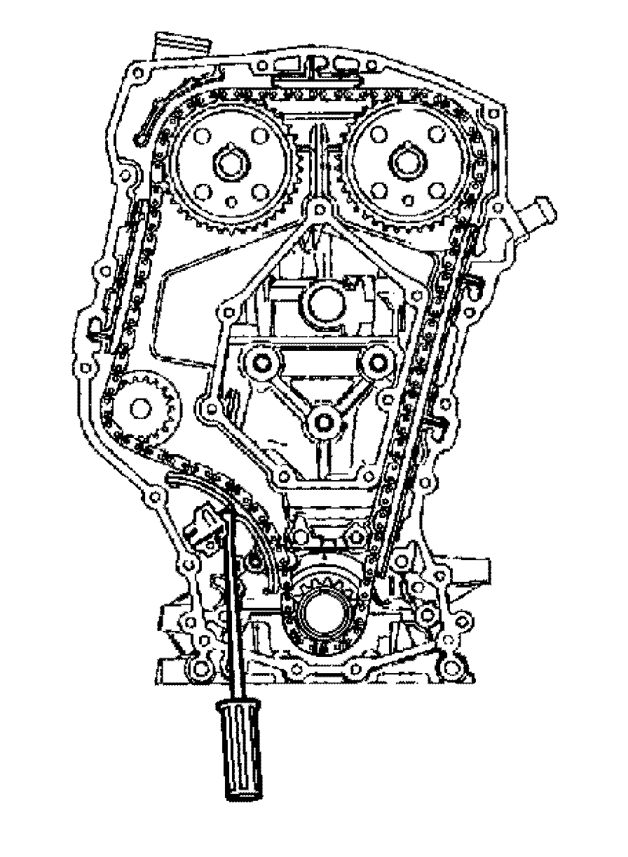
3. Rotate the crankshaft clockwise (as viewed from the front of the engine, normal rotation) until the camshaft sprocket timing dowel pin holes align with the holes in the timing chain housing.
pic 8
4. Set the crankshaft sprocket keyway pointing upwards. Align with the centerline of the cylinder bores. This is the timed position.
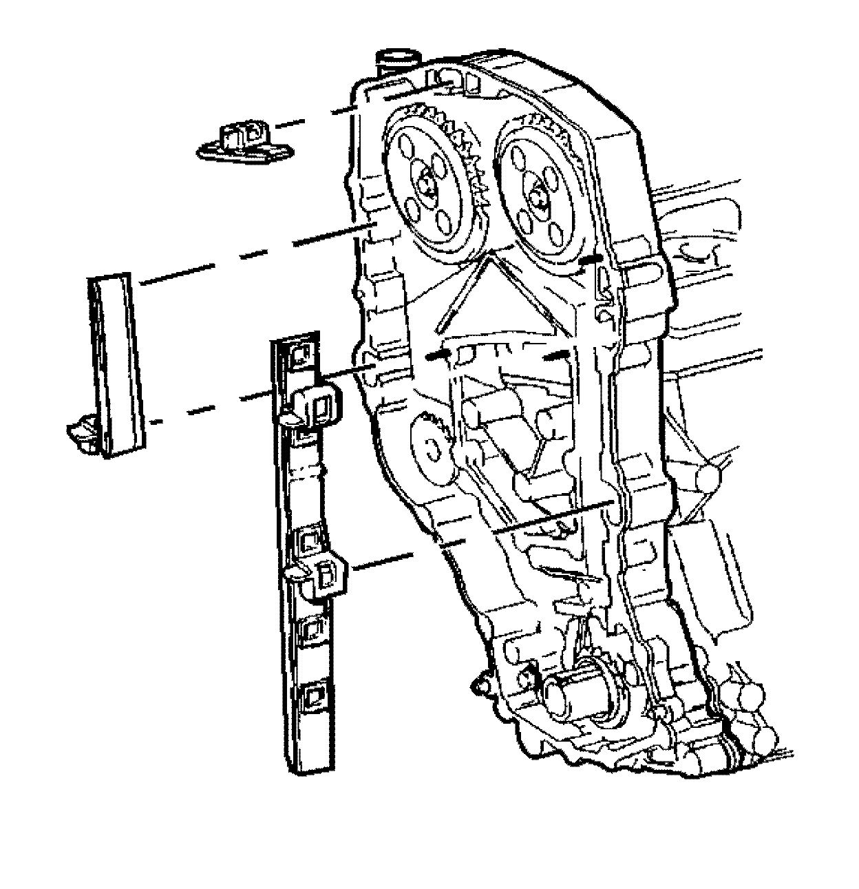
5. Remove the timing chain guides.
6. Raise and support the vehicle.
7. Ensure that all of the slack in the timing chain is above the tensioner assembly.
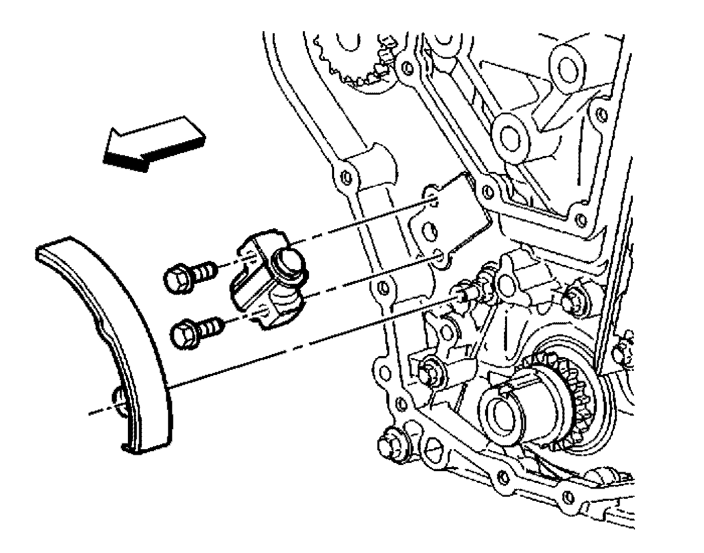
8. Remove the timing chain tensioner bolts and the tensioner.
pic 9
9. Remove the tensioner shoe. Use a small locking ring plier in order to engage the hole in the locking tab and remove the shoe from the stud.
pic 10
Notice: Do not attempt to pry the sprocket off the camshaft or damage to the sprocket or chain housing could occur.
Important: Mark the timing chain and the crankshaft sprocket prior to removal. If the chain or the crankshaft sprocket is installed with the wear pattern in the opposite direction, noise and increased wear may occur.
10. Mark the crankshaft sprocket and the timing chain outer surface.
11. Remove the timing chain.
12. Lower the vehicle.
pic 11
13. Holding the intake camshaft sprocket with J 39579 , remove the sprocket bolt and washer.
14. Remove the washer from the bolt and rethread the bolt back into the camshaft.
15. Using a 3-jaw puller and the relief holes in the sprocket, remove the intake camshaft sprocket.
16. Repeat this procedure for the exhaust camshaft sprocket.
17. Clean the old sealant from the bolt with a wire brush.
18. Clean the threaded hole in the camshaft with a round nylon bristle brush.
19. Inspect the parts for wear. Replace the parts as necessary. Some scoring of the timing chain shoe and the guides is normal.
20. Replace the timing chain shoe or guides if the scoring exceeds 1.12 mm (45 in).
Installation Procedure
pic 12
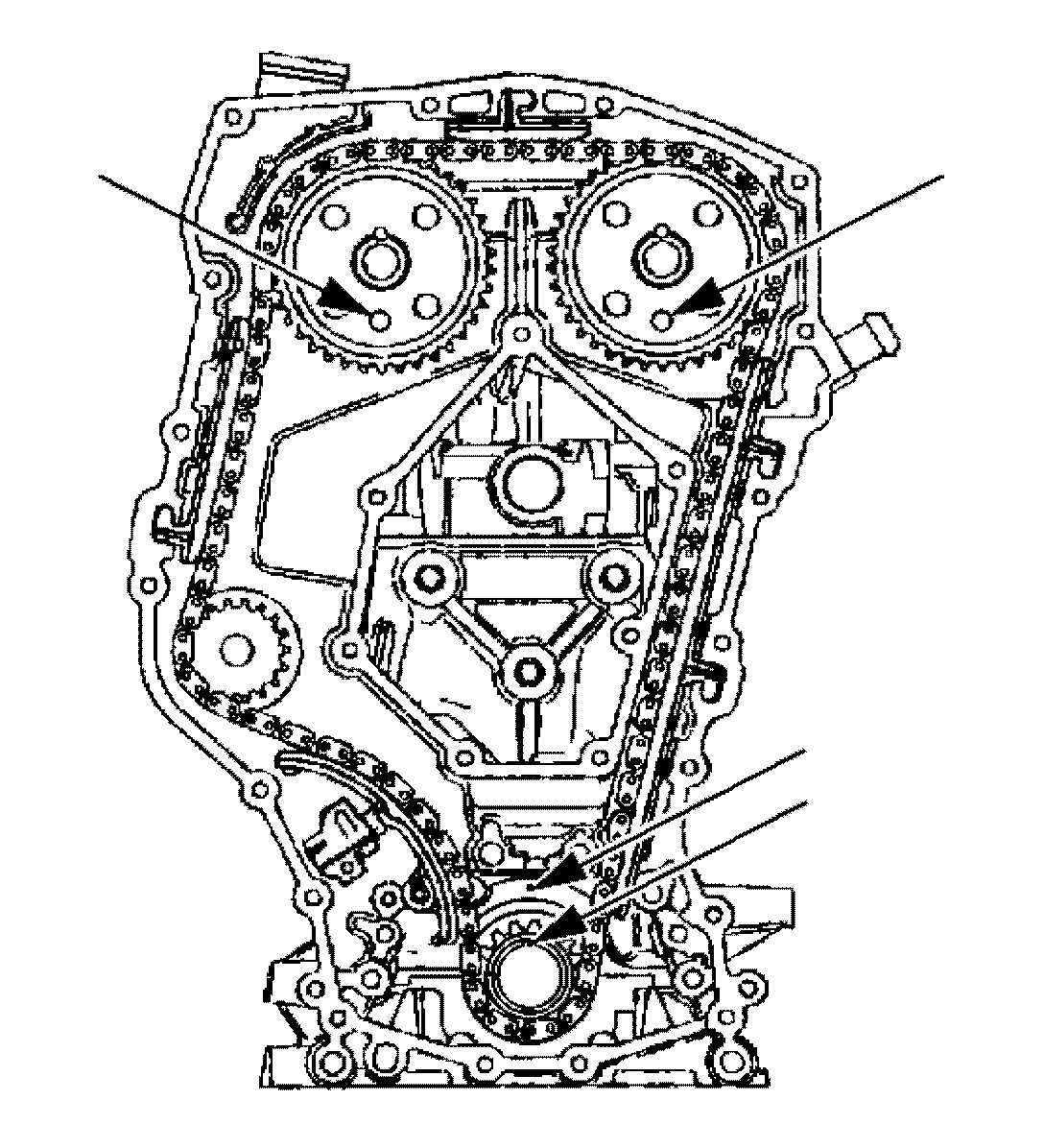
1. Use Adhesive/Sealant Compound GM P/N 12345493 or equivalent on the camshaft sprocket bolt. Install the intake and exhaust camshaft sprockets onto the camshafts with the marked surface showing.
Notice: Use the correct fastener in the correct location. Replacement fasteners must be the correct part number for that application. Fasteners requiring replacement or fasteners requiring the use of thread locking compound or sealant are identified in the service procedure. Do not use paints, lubricants, or corrosion inhibitors on fasteners or fastener joint surfaces unless specified. These coatings affect fastener torque and joint clamping force and may damage the fastener. Use the correct tightening sequence and specifications when installing fasteners in order to avoid damage to parts and systems.
2. Install the retaining bolts and washers to the intake and exhaust camshaft sprockets.
Tighten the bolts to 70 Nm (52 ft. lbs.) while holding the sprockets with the J 39579.
3. Install the J 36800 through the holes in the camshaft sprockets into the holes in the timing chain housing. This will position the camshaft for correct timing.
4. If the camshafts are out of position (you must rotate the camshaft more than 1/8 turn in order to install the alignment dowel pins), use the following procedure.
4.1 Rotate the crankshaft 90 degrees clockwise off of the TDC in order to give the valves adequate clearance to open.
4.2 Once the camshafts are in position and the dowels installed, rotate the crankshaft counter clockwise back to the top dead center.
pic 13
Notice: Do not rotate the crankshaft clockwise to TDC. Valve or piston damage could occur.
Important: The side of the timing chain that was marked during removal must be showing when the chain is installed.
5. Install the timing chain over the exhaust camshaft sprocket, around the coolant pump, and around the crankshaft sprocket.
5.1 Remove the alignment dowel pin from the intake camshaft.
5.2 Using the J 39579 , rotate the intake camshaft sprocket counterclockwise enough in order to slide the timing chain over the intake camshaft sprocket.
5.3 Release the J 39579 . The length of the chain between the 2 camshaft sprockets will tighten.
5.4 If properly timed the intake camshaft alignment dowel pin should slide in easily. If the dowel pin does not fully index, the camshafts are not timed correctly and the procedure must be repeated.
6. Leave the alignment dowel pins installed.
7. Raise and support the vehicle.
8. The timing marks on the crankshaft and on the cylinder block should be aligned when the slack is removed from the chain linking the intake camshaft sprocket and the crankshaft sprocket. If the marks are not aligned, move the chain one tooth forward or rearward, remove the slack and re-examine the marks.
pic 14
Important: Use the following steps in order to reset the timing chain tensioner assembly to the zero position.
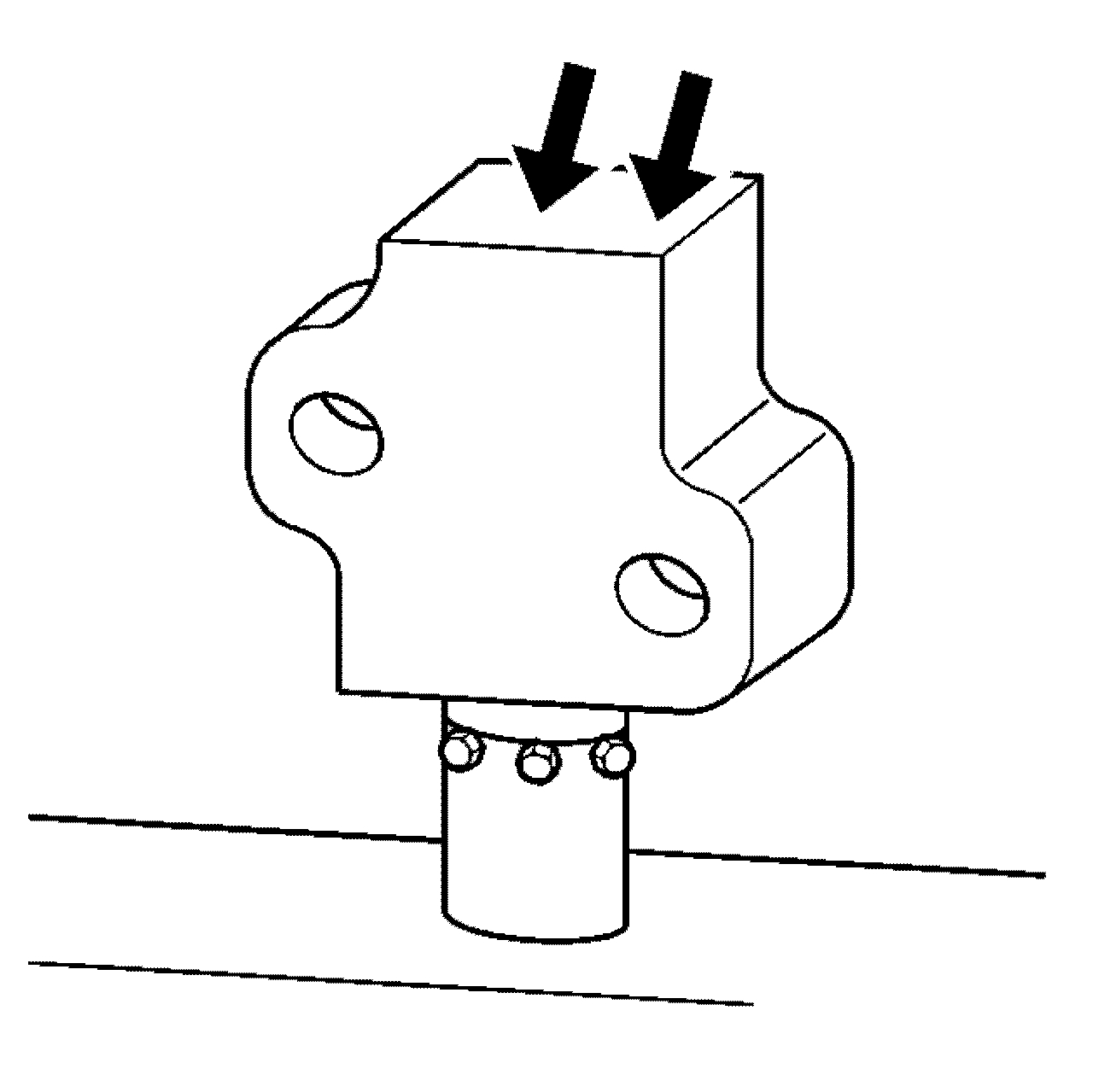
9. Reset the timing chain tensioner assembly.
9.1 Insert the tensioner plunger assembly into the tensioner housing.
9.2 With the tensioner plunger fully extended, turn the complete assembly upside down on a bench or other flat surface.
9.3 With the plunger face against the workbench, press firmly on the bottom of the tensioner housing.
9.4 Compress the plunger until the plunger is seated flush in the tensioner.
pic 15
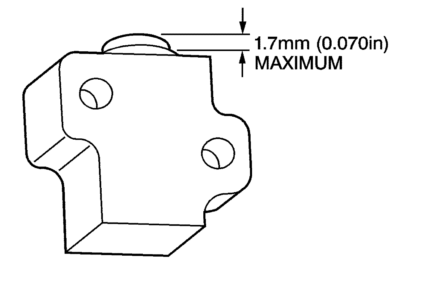
10. Check the plunger to make sure the plunger is out of the cylinder at the correct dimension. The correct dimension for the plunger to extend out of the cylinder is 1.7 mm (0.07 in.) maximum.
pic 16
11. Loosely install the tensioner assembly and bolts to the timing chain housing.
12. Install the timing chain tensioner shoe on the stud.
13. Apply hand pressure to the timing chain tensioner shoe until the locking tab seats in the groove in the stud.
14. Tighten the timing chain tensioner bolts. Do Not overtighten.
Tighten the bolts to 10 Nm (89 in. lbs.).
pic 17
Important: the timing chain tensioner is not released from the installation position, engine damage will occur when the engine is started.
15. Release the timing chain tensioner plunger.
15.1 Using a flat blade screwdriver, cotter pin remover, or similar tool, press firmly against the face of the timing chain tensioner plunger.
Important: If the timing chain tensioner cannot be depressed, the plunger is not properly reset and the procedure for resetting the timing chain tensioner should be repeated.
15.2 Depress the timing chain tensioner plunger until the plunger is bottomed out in the bore of the timing chain tensioner.
15.3 Release the tensioner plunger. the plunger should press firmly against the back of the timing chain tensioner shoe.
16. Remove J 36800 from the camshaft sprockets.
17. Rotate the crankshaft clockwise 2 full rotations. Align the crankshaft keyway with the mark on the cylinder block, and reinstall the alignment dowel pins. The pins should slide in easily if the engine is timed correctly.
pic 18
18. Install the timing chain guides.
19. Install the engine front cover. See: Timing Cover > Procedures > Engine Front Cover Replacement
20. Connect the negative battery cable.
Tighten the bolt to 16 Nm (12 ft. lbs.).
__________________________________________________
Images (Click to make bigger)
SPONSORED LINKS
Saturday, May 4th, 2019 AT 6:57 PM