Check engine light on

Tiny
ANGELWILKINS
  • MEMBER
  • 2002 MITSUBISHI GALANT
  • 2.4L
  • 4 CYL
  • AUTOMATIC
  • 143,000 MILES
After using a scanner came up with po335 and po340 codes. I replaced camshaft sensor and crankshaft sensor (new) and disconnected the battery and still have the codes. Car starts and runs fine, but will not pass emission test. Help please.
Sunday, May 27th, 2018 AT 5:47 PM

19 Replies

Tiny
JACOBANDNICKOLAS
  • MECHANIC
  • 108,320 POSTS
Hi and thanks for using 2CarPros. Com. If you replaced the parts, you need to clear the codes using a scanner and not disconnecting the battery. If it is a hard code, it will remain.

Let me know if this is what you have done.

Thanks,
Joe
Was this
answer
helpful?
Yes
No
+1
Sunday, May 27th, 2018 AT 9:08 PM
Tiny
ANGELWILKINS
  • MEMBER
  • 10 POSTS
Well let me tell you that was the first thing I did. I cleared the codes with the scanner and it was the same, so I disconnected the battery and still the same. Of course the check engine light was off after I did this with the scanner and the battery, but when I shut off the engine and turn it on again came up with the same codes.
Was this
answer
helpful?
Yes
No
-1
Monday, May 28th, 2018 AT 12:26 PM
Tiny
JACOBANDNICKOLAS
  • MECHANIC
  • 108,320 POSTS
Hi again. I did some research and found the following technical service bulletin. I feel it relates to the issue you have. Take a look at it and let me know your thoughts.

No: TT-133-13-003

DATE: December, 2006

MODEL: see Below

SUBJECT:
MFI DTC P0335 AND/OR P0340 AFTER ENGINE REPAIR
MFI DTC P0335 and/or P0340 After Engine Repair - 2000-2005 Eclipse/Eclipse Spyder and 1999-2003 Galant 2.4L engine. The camshaft position sensor sensing blade, p/n MD346813, is for models up to and including 2001. On 2002 models, the sensing blade (p/n MD374910) changed. The new part can also be used in an older engine. However, the old part cannot be used in a later engine. If an old part is used in a 2002 or later engine, MFI codes P0335 and/or P0340 will set.

Did you replace the component mentioned? Has there ever been major engine work done? Has the head ever been changed?

Let me know.

Joe
Was this
answer
helpful?
Yes
No
Tuesday, May 29th, 2018 AT 6:51 PM
Tiny
ANGELWILKINS
  • MEMBER
  • 10 POSTS
My mechanic only replaced the crank shaft sensor and the cam shaft sensor. But not that blade you talking about. If is possible for you to send me photo of this part and where is located? Please.
Was this
answer
helpful?
Yes
No
+1
Thursday, May 31st, 2018 AT 6:46 AM
Tiny
JACOBANDNICKOLAS
  • MECHANIC
  • 108,320 POSTS
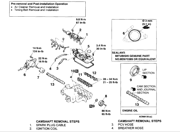
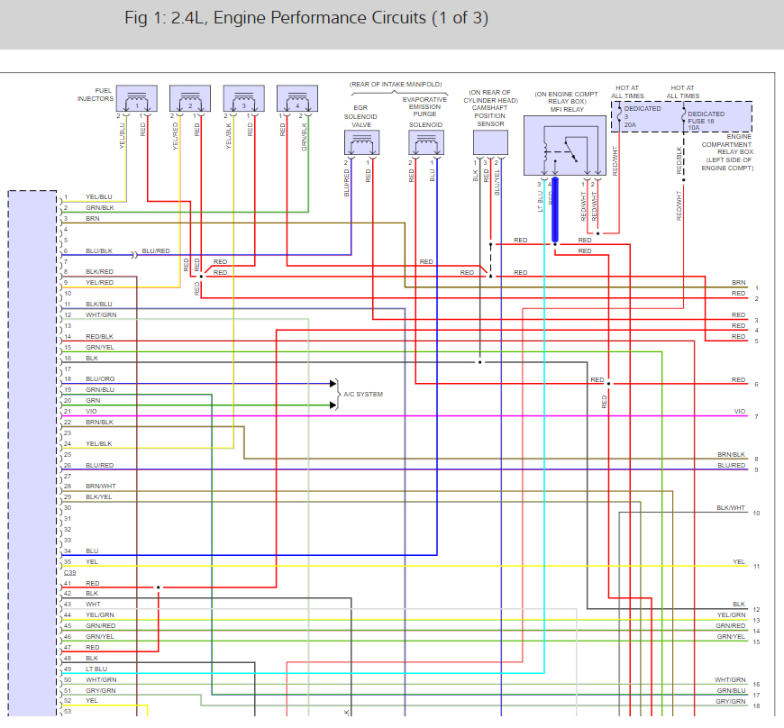
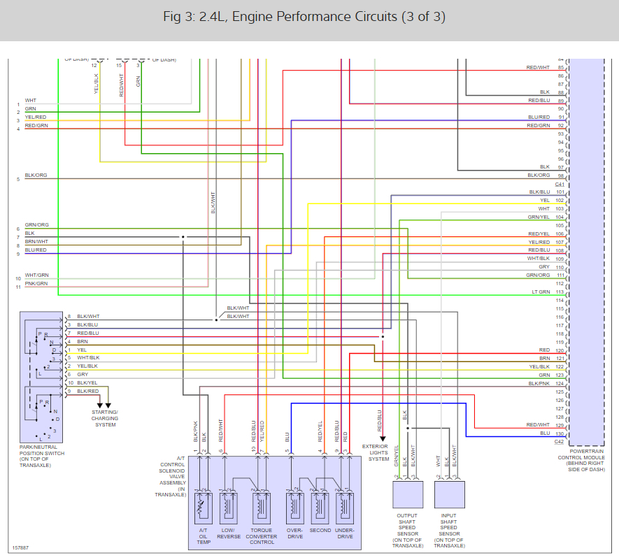
Not a problem. See number 7 in the attached pictures. (First two pictures)

Since both the P0335 and P0340 deal with the cam sensor, here is diagnostic information specific to those codes. It is quite extensive plus there are several pictures attached.

2002 Mitsubishi Galant DE L4-2350cc 2.4L SOHC MFI
Vehicle  A L L Diagnostic Trouble Codes ( DTC )  Testing and Inspection  P Code Charts  P0335
P0335
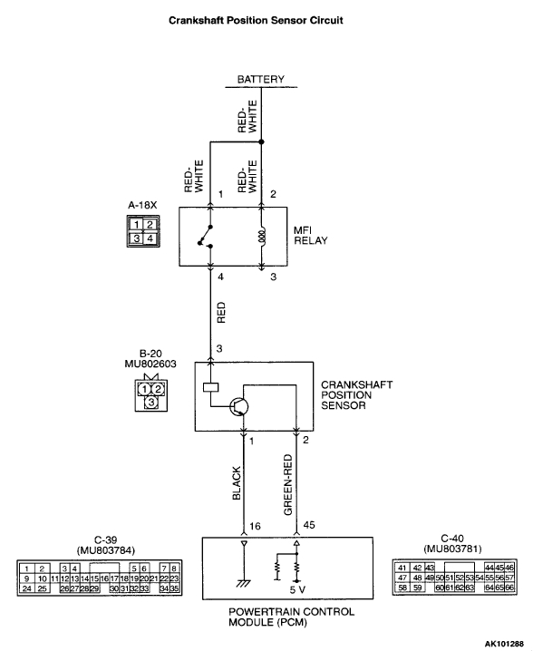
Crankshaft Position Sensor Circuit
Connectors
CIRCUIT OPERATION
The crankshaft position sensor power is supplied from the MFI relay (terminal 4).
Terminal 1 of the crankshaft position sensor is grounded with PCM (terminal 16).
A 5-volt voltage is applied on the crankshaft position sensor output terminal (terminal 2) from the PCM (terminal 45). The crankshaft position sensor generates a pulse signal when the output terminal is opened and grounded.
TECHNICAL DESCRIPTION
The crankshaft position sensor detects the crank angle (position) of each cylinder, and converts that data to pulse signals, which are then input to the PCM.
When the engine is running, the crankshaft position sensor outputs a pulse signal.
The PCM checks whether pulse signal is input while the engine is cranking.
DTC SET CONDITIONS
Check Conditions
Engine is being cranked.
Judgment Criteria
Crankshaft position sensor output voltage has not changed (no pulse signal is input) for 2 seconds.
Check Conditions, Judgment Criteria
Normal signal pattern has not been input for cylinder identification from the crankshaft position sensor signal and camshaft position sensor signal for 2 seconds.
TROUBLESHOOTING HINTS (The most likely causes for this code to be set are:)
Crankshaft position sensor failed.
Open or shorted crankshaft position sensor circuit, or loose connector.
PCM failed.
DIAGNOSIS
Required Special Tools
MB991502; Scan Tool (MUT-II)
MB991658: Test Harness Set
STEP 1. Using scan tool MB991502, check data list item 22: Crankshaft Position Sensor.
CAUTION: To prevent damage to scan tool MB991502, always turn the ignition switch to the "LOCK" (OFF) position before connecting or disconnecting scan tool MB991502.
Connect scan tool MB991502 to the data link connector.
Start the engine and run at idle.
Set scan tool MB991502 to the data reading mode for item 22, Crankshaft Position Sensor.
The tachometer and engine speed indicated on the scan tool should much.
Turn the ignition switch to the "LOCK" (OFF) position.
Q: Is the sensor operating properly?
YES: It can be assumed that this malfunction is intermittent.
Refer to How to Use Troubleshooting/Inspection Service Points.
NO: Go to Step 2.
STEP 2. Using the oscilloscope, check the crankshaft position sensor.
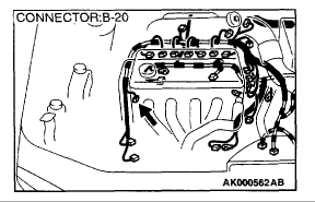
Do not disconnect the crankshaft position sensor connector B-20.
Connect the oscilloscope probe to terminal 2 of the crankshaft position sensor by backprobing.
NOTE: Connect the oscilloscope probe to terminal 45 by backprobing when measuring with the PCM connector.
Start the engine and run at idle.
Check the waveform.
The waveform should show a pattern similar to the illustration.
Turn the ignition switch to the "LOCK" (OFF) position.
Q: Is the waveform normal?
YES: Go to Step 3.
NO: Go to Step 5.
STEP 3. Check connector B-20 at the crankshaft position sensor for damage.
Q: Is the connector in good condition?
YES: Go to Step 4.
NO: Repair or replace it. Refer to Harness Connector Inspection. Then go to Step 21.
STEP 4. Using scan tool MB991502, check data list item 22: Crankshaft Position Sensor.
CAUTION: To prevent damage to scan tool MB991502, always turn the ignition switch to the "LOCK" (OFF) position before connecting or disconnecting scan tool MB991502.
Connect scan tool MB991502 to the data link connector.
Turn the ignition switch to the "ON" position.
Set scan tool MB991502 to the data reading mode for item 22, Crankshaft Position Sensor.
The tachometer and engine speed indicated on the scan tool should much.
Turn the ignition switch to the "LOCK" (OFF) position.
Q: Is the sensor operating properly?
YES: It can be assumed that this malfunction is intermittent.
Refer to How to Use Troubleshooting/Inspection Service Points.
NO: Replace the PCM. Then go to Step 21.
STEP 5. Check connector B-20 at the crankshaft position sensor for damage.
Q: Is the connector in good condition?
YES: Go to Step 6.
NO: Repair or replace it. Refer to Harness Connector Inspection. Then go to Step 21.
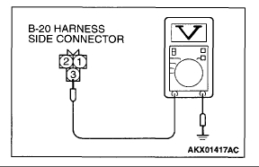
STEP 6. Check the sensor supply voltage at crankshaft position sensor harness side connector B-20.
Disconnect the connector B-20 and measure at the harness side.
Turn the ignition switch to the "ON" position.
Measure the voltage between terminal 2 and ground.
Voltage should be between 4.8 and 5.2 volts.
Turn the ignition switch to the "LOCK" (OFF) position.
Q: Is the voltage normal?
YES: Go to Step 11.
NO: Go to Step 7.
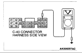
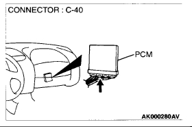
STEP 7. Check the sensor supply voltage at PCM connector C-40 by backprobing.
Do not disconnect the PCM connector C-40.
Disconnect the crankshaft position sensor connector B-20.
Turn the ignition switch to the "ON" position.
Measure the voltage between terminal 45 and ground by backprobing.
Voltage should be between 4.8 and 5.2 volts.
Turn the ignition switch to the "LOCK" (OFF) position.
Q: Is the voltage normal?
YES: Go to Step 8.
NO: Go to Step 9.
STEP 8. Check connector connector C-40 at PCM for damage.
Q: Is the connector in good condition?
YES: Repair it because of open circuit between crankshaft position sensor connector B-20 terminal 2 and PCM connector C-40 terminal 45. Then go to Step 21.
NO: Repair or replace it. Refer to Harness Connector Inspection. Then go to Step 21.
STEP 9. Check connector C-40 at PCM for damage.
Q: Is the connector in good condition?
YES: Go to Step 10.
NO: Repair or replace it. Refer to Harness Connector Inspection. Then go to Step 21.
STEP 10. Check for short circuit to ground between crankshaft position sensor connector B-20 terminal 2 and PCM connector C-40 terminal 45.
Q: Is the harness wire in good condition?
YES: Replace the PCM. Then go to Step 21.
NO: Repair it. Then go to Step 21.
STEP 11. Check the power supply voltage at crankshaft position sensor harness side connector B-20.
Disconnect the connector B-20 and measure at the harness side.
Turn the ignition switch to the "ON" position.
Measure the voltage between terminal 3 and ground.
Voltage should be battery positive voltage.
Turn the ignition switch to the "LOCK" (OFF) position.
Q: Is the voltage normal?
YES: Go to Step 13.
NO: Go to Step 12.
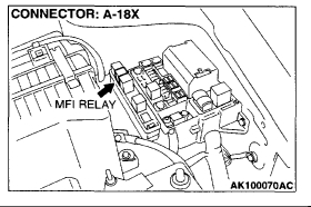
STEP 12. Check connector B-18X at MFI relay for damage.
Q: Is the connector in good condition?
YES: Repair harness wire between MFI relay connector B-18X terminal 4 and crankshaft position sensor connector B-20 terminal 3 because of open circuit or short circuit to ground. Then go to Step 21.
NO: Repair or replace it. Refer to Harness Connector Inspection. Then go to Step 21.
STEP 13. Check the continuity at crankshaft position sensor harness side connector B-20.
Disconnect the connector B-20 and measure at the harness side.
Check for the continuity between terminal 1 and ground.
Should be less than 2 ohm.
Q: Is the continuity normal?
YES: Go to Step 16.
NO: Go to Step 14.
STEP 14. Check connector C-40 at PCM for damage.
Q: Is the connector in good condition?
YES: Go to Step 15.
NO: Repair or replace it. Refer to Harness Connector Inspection. Then go to Step 21.
STEP 15. Check for open circuit and harness damage between crankshaft position sensor connector B-20 terminal 1 and PCM connector C-39 terminal 16.
Q: Is the harness wire in good condition?
YES: Replace the PCM. Then go to Step 21.
NO: Repair it. Then go to Step 21.
STEP 16. Check connector B-18X at the MFI relay for damage.
Q: Is the harness connector in good condition?
YES: Go to Step 17.
NO: Repair or replace it. Refer to Harness Connector Inspection. Then go to Step 21.
STEP 17. Check connector C-115 at ECM (M/T> or connector C-40 at PCM for damage.
Q: Is the connector in good condition?
YES: Go to Step 18.
NO: Repair or replace it. Refer to Harness Connector Inspection. Then go to Step 21.
STEP 18. Check for harness damage between MFI relay connector B-18X terminal 4 and crankshaft position sensor connector B-20 terminal 3.
Q: Is the harness wire in good condition?
YES: Go to Step 19.
NO: Repair it Then go to Step 21.
STEP 19. Check for harness damage between crankshaft position sensor connector B-20 terminal 2 PCM connector C-40 terminal 45.
Q: Is the harness wire in good condition?
YES: Go to Step 20.
NO: Repair it. Then go to Step 21.
STEP 20. Check the crankshaft position sensor vane.
Q: Is the vane in a good condition?
YES: Replace the crankshaft position sensor. Then go to Step 21.
NO: Repair it. Then go to Step 21.
STEP 21. Test the OBD-II drive cycle.
Carry out a test drive with the drive cycle pattern. Refer to Procedure 6 - Other Monitor.
Check the diagnostic trouble code (DTC).
Q: Is the DTC P0335 is output?
YES: Retry the troubleshooting.
NO: The inspection is complete.

______________________________________________________
Was this
answer
helpful?
Yes
No
+1
Thursday, May 31st, 2018 AT 8:28 PM
Tiny
ANGELWILKINS
  • MEMBER
  • 10 POSTS
Okay, a mechanic told me that the crankshaft angle plate and/or the camshaft angle plates could be the issue, but I do not know where these two are located and the part number or how much they cost. Do you have any idea of these? Can you send me some pictures where these are located in my car? Thanks for your help.
Was this
answer
helpful?
Yes
No
+1
Saturday, June 2nd, 2018 AT 1:36 PM
Tiny
KEN L
  • MASTER CERTIFIED MECHANIC
  • 43,072 POSTS
These codes can be caused by the timing belt being off one tooth. Does the car run or?

Here is a guide that will help you check the camshaft timing:

https://www.2carpros.com/diagrams/mitsubishi/galant/2002

Please let us know what happens.

Cheers, Ken
Was this
answer
helpful?
Yes
No
Tuesday, June 5th, 2018 AT 11:24 AM
Tiny
ANGELWILKINS
  • MEMBER
  • 10 POSTS
Yes the car runs fine, very smooth, shifting gears fine and it has a new timing belt. The timing is fine because I have a second mechanic working on it and put a new one right in front of me. The computer is fine also because it is sending the right voltage to the sensor and back. Both camshaft and crankshaft plates are fine. Both sensors are fine not showing any damage/scratches by the plates. The problem is when he reset the code with the scanner and the car start/runs fine but once shut off engine light comes back, even with the car running. He put the scanner it reads same codes are back without the engine light on. This mechanic has an expensive computer reader or scanner to do the job and he says the computer its fine. I do not know what else can it be.
Was this
answer
helpful?
Yes
No
Wednesday, June 6th, 2018 AT 4:37 PM
Tiny
KEN L
  • MASTER CERTIFIED MECHANIC
  • 43,072 POSTS
I would check the wiring between the computer and the sensors for high resistance. Here is a guide to help and and the wiring diagrams:

https://www.2carpros.com/articles/how-to-check-wiring

If everything checks out it only leaves the camshaft timing being off or the computer is bad.

Check out the diagrams (below). Please let us know what you find. We are interested to see what it is.

Cheers, Ken
Was this
answer
helpful?
Yes
No
+2
Thursday, June 7th, 2018 AT 6:06 PM
Tiny
ANGELWILKINS
  • MEMBER
  • 10 POSTS
This is going to take more time that I ever though. My mechanic said that all the wiring is fine, the only one thing left is the computer. Because the timing is fine, it has been double checked by two mechanics. I will let you know after the new computer is installed, but when this is done what I need to do after I install the new computer? Any steps I need to follow?
Was this
answer
helpful?
Yes
No
Sunday, June 17th, 2018 AT 3:18 PM
Tiny
KEN L
  • MASTER CERTIFIED MECHANIC
  • 43,072 POSTS
It makes sense the computer is bad it happens all the time. Some computers are plug and play yours is one of them if you get a used one. If you get a new one it will need to be programmed into the car. Here is the location please let us know what happens. (Below)
Was this
answer
helpful?
Yes
No
Monday, June 18th, 2018 AT 10:00 AM
Tiny
ANGELWILKINS
  • MEMBER
  • 10 POSTS
Hello again, just to give you an update; new/used ECU was installed, but engine just cranking and wont start, the mechanic told me that now I need to program the key so will communicate with the computer, good thing that engine check light its gone and hope after the programming of the key works fine. However, locksmith said that I need to get some others parts (ignition key cylinder/module from fuse box under the hood ) from the same vehicle that ECU was pulled, in order to program the key. Now my question to you, is this necessary to program a key for this Mitsubishi? What other things needs to be done after that?
Was this
answer
helpful?
Yes
No
Saturday, June 23rd, 2018 AT 6:52 PM
Tiny
KEN L
  • MASTER CERTIFIED MECHANIC
  • 43,072 POSTS
You should be able to have a shop reprogram it for you for about $130.00. The only reason you would need the ignition key module is if you do not want to reprogram. That way the RF chip in the key will match the computer.
Was this
answer
helpful?
Yes
No
Sunday, June 24th, 2018 AT 12:08 PM
Tiny
ANGELWILKINS
  • MEMBER
  • 10 POSTS
Okay, so far I installed the ignition key module and the module for the key under the dashboard and I am using the old key and still not responding. Now the key guy is going to get a new key because the old key I cannot reprogram it. And here I am waiting for this guy almost two days now and I cannot move the car to a shop because does not start. I am stuck with this. Anyways I will let you guys know how this ends. Hope I do not get another surprise.
Was this
answer
helpful?
Yes
No
Friday, June 29th, 2018 AT 5:50 PM
Tiny
KEN L
  • MASTER CERTIFIED MECHANIC
  • 43,072 POSTS
Once it is programmed you should be fine, let us know.
Was this
answer
helpful?
Yes
No
Saturday, June 30th, 2018 AT 11:34 AM
Tiny
ANGELWILKINS
  • MEMBER
  • 10 POSTS
Okay, the key guy could not do anything. Vehicle gives P1610 code, and he said there is a problem with any of the three components I replaced and I will not be able to program the key or start the vehicle, unless I fix one of the three components. Now what should I do? Should I removed the ignition key module and just use the new/used computer and see what happen or removed one by one until I find the problem? What will you recommend? The three components I replaced are: 1. A black box under the driver side next to the fuses (I think this is the ignition key module). 2. Then a round ring where you put the key in to start the vehicle (some type of antenna). 3. The computer (or ECU. What should I do?
Was this
answer
helpful?
Yes
No
Monday, July 9th, 2018 AT 5:35 PM
Tiny
ROL*S.
  • MECHANIC
  • 61 POSTS
Hi Angel, those parts you installed are all out of one car right? Except for the key.
I think what happened was the immobilizer-ECU saw an unrecognizable key and send that info to the PCM, so p1610 was generated, PCM made it un-startable. And without a scanner that can program, I think you have to basically lucked out. You have access to a regular scanner? One that can erase codes? Need to try and get rid of 1610. And if there is no scanner, try to clear it by disconnecting battery. Thing about it is, without a scanner, you do not know if the code got cleared. Then the key needs to be left in the run position for a half hour. That way the immobilizer-ECU does not think an unrecognizable key is not trying to start it and the key turns familiar. If that happens, the ECU tells the PCM its all good, the PCM does not go into un-start able mode and it fires up. Of course you have to make sure the battery is charged enough to sit for a half an hour with the key on run then still be able to crank after. So do put a charger on it. It is either that or find a shop or a dealer that can program it. Good luck Angel, let us know how it turned out.
Was this
answer
helpful?
Yes
No
Friday, July 13th, 2018 AT 8:38 AM
Tiny
ANGELWILKINS
  • MEMBER
  • 10 POSTS
Hi guys, well I think I am gonna keep looking for the right guy to program my ECU because the last one could not do it. So until then everything still the same. Any ways I have a friend who owns a 2008 Mitsubishi lancer LS automatic and he wants to change the transmission because his is not shifting right, so he wants to know if he install the new/used transmission he needs to program it like I need to do with my Galant? Or just install it and drive it? What can you tell him about his situation?
Was this
answer
helpful?
Yes
No
Monday, August 6th, 2018 AT 5:21 PM
Tiny
KEN L
  • MASTER CERTIFIED MECHANIC
  • 43,072 POSTS
The transmission should be okay. I have not heard of having to program the valve body but you never know. Let us know what happens.
Was this
answer
helpful?
Yes
No
Tuesday, August 7th, 2018 AT 9:57 AM

Please login or register to post a reply.

Related Check Engine Light Content

Sponsored links