Alternator wiring diagram?

Tiny
TERRY BOYD
  • MEMBER
  • 1998 DODGE CARAVAN
  • 3.3L
  • 6 CYL
  • 2WD
  • AUTOMATIC
  • 310,000 MILES
I need to know precisely where to find the fusible link between the alternator and the battery, since both lines to the alternator connections run in one wrapped bundle.

Suspect that fusible link may be the problem as to why not only the alternator light is on, but I had weird glitches in instrument panel (loss of tachometer and speedometer, ABS light coming on). In process of changing the PCM which I suspect may have received damage to the voltage regulator chip inside. Really getting tired of dismantling the top of my engine compartment if you know my meaning. And I need my one and only transportation!

Added Information:
New alternator and new battery installed prior to symptoms described.
Monday, February 20th, 2017 AT 11:13 AM

59 Replies

Tiny
STEVE W.
  • MECHANIC
  • 12,978 POSTS
The link is in the positive cable right near the battery terminal. Check the ASD relay as well. Here is the wiring diagrams for the alternator so you can see how the system works with a guide to test the wiring as well.

https://www.2carpros.com/articles/how-to-check-wiring

Check out the diagrams (Below). Please let us know what you find. We are interested to see what it is.
Was this
answer
helpful?
Yes
No
+9
Monday, February 20th, 2017 AT 12:03 PM
Tiny
TERRY BOYD
  • MEMBER
  • 5 POSTS
Will check. Thanks
Was this
answer
helpful?
Yes
No
+2
Monday, February 20th, 2017 AT 12:41 PM
Tiny
TERRY BOYD
  • MEMBER
  • 5 POSTS
Steve W. That is not it! This is not letting me add a photo as it should. So I cannot show you. Main big cable from post is to the starter/starter solenoid, smaller red cable (ten gauge) goes to the PDC, also to the PDC is a dark green cable (ten gauge) and that is to the PCM. No fusible links. I am not a pro mechanic, but I do know what a fusible link is and where they should be placed and placing this one at the target area (battery) is not the proper place. Logically a fusible link is placed close to the source of the powering device in order to protect the system and targeted area which in this case is the battery and PCM since the voltage regulator circuitry and control chip are located within the PCM.

Thanks for the help, but not for this computer controlled system without an external voltage regulator unlike a 1970's model of Dodge.
Was this
answer
helpful?
Yes
No
+2
Tuesday, February 21st, 2017 AT 6:07 AM
Tiny
TERRY BOYD
  • MEMBER
  • 5 POSTS
For all With this problem.
Check with your local auto parts store and have them look up your vehicle to see whether your car has a fusible link in the charging system. I did just that since my local Dodge dealer would not tell me if it did or not. This particular model of Grand Caravan does not have a fusible link in the charging system. The reason given were the amount of relay, fuses and other safeguards installed in the system. The voltage regulating system is a control chip in the voltage regulator circuitry that's inside the PCM and cannot be repaired independently, the entire PCM must be replaced.
Was this
answer
helpful?
Yes
No
+3
Tuesday, February 21st, 2017 AT 9:20 AM
Tiny
STEVE W.
  • MECHANIC
  • 12,978 POSTS
I guess that Dodge must lie then.

These are the wiring diagrams for that vehicle and both show that it has a fusible link (A111 Dark. Green ten gauge) spliced to the black with gray wire that goes to the alternator at the battery end.

And in your complaint about being given wrong information you state "Main big cable from post is to the starter/starter solenoid, smaller red cable (ten gauge) goes to the PDC, also to the PDC is a dark green cable (ten gauge) and that's to the PCM. NO FUSIBLE LINKS"

The dark green wire is the fusible link. It is bonded (electrical splice 09) to the Black with gray stripe about one foot down the harness.

Go look at the wire on the battery terminal of your alternator. What color is it?
Was this
answer
helpful?
Yes
No
+2
Tuesday, February 21st, 2017 AT 10:17 AM
Tiny
KEN L
  • MASTER CERTIFIED MECHANIC
  • 42,909 POSTS
I agree with Steve W. The fusible links are near the battery on the fender well of the drivers side tire and they fail often I have replaced many myself.

Ken - Site Admin
Was this
answer
helpful?
Yes
No
+5
Tuesday, February 21st, 2017 AT 6:51 PM
Tiny
TERRY BOYD
  • MEMBER
  • 5 POSTS
Maybe these will help what I said. And as I said there's no fusible link in this vehicle. Left RED is main, right RED leads to PDC and that Dark Green (same color as my schematic says the fusible link A111 is) leads from PDC to the PCM. The bundle under the PDC between the PDC and PCM has the Red Main in it but NO FUSIBLE LINK. So, after tracing every bundle from battery to alternator including the leads to the ignition system and fuel injectors and not finding anything I went to the Dodge Dealer parts store to get a brand new ASD RELAY and asked their chief mechanic (showing every photo I had taken). He looked it up and looked up my VIN and found that this 1998 Grand Caravan Sport does not have a fusible link. So, when I post what I am told by a dealer's mechanic after an hour and twenty minutes of searching and waiting it's not my imagination. Besides it makes no difference now anyway because I had to order a whole new PCM after having this one checked out because the voltage circuitry chip smoked out. Presumption is by what the codes showed is that it lost ground apparently of which I have no doubt since that fender was severely damaged in an accident 2 yrs ago. Just one of several parts that had to be replaced in time as a result. Like I saud, Thanks For Your Help!
Was this
answer
helpful?
Yes
No
+1
Tuesday, February 21st, 2017 AT 7:25 PM
Tiny
CARADIODOC
  • MECHANIC
  • 33,743 POSTS
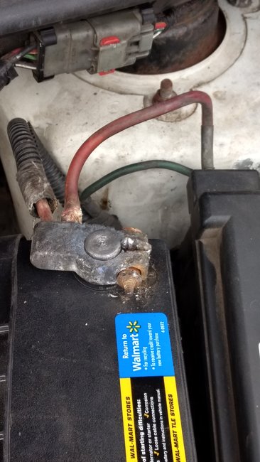
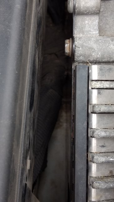
There's a lot of misinformation here. You found the dull dark green wire. That is the fuse link wire. Tug on it. If it acts like a wire, it's good. If it acts like a rubber band, it's burned open. The problem is it doesn't come off the battery cable like in years past. The smaller positive battery wire bolts to the under-hood fuse box. That connection is where the fuse link wire is bolted.

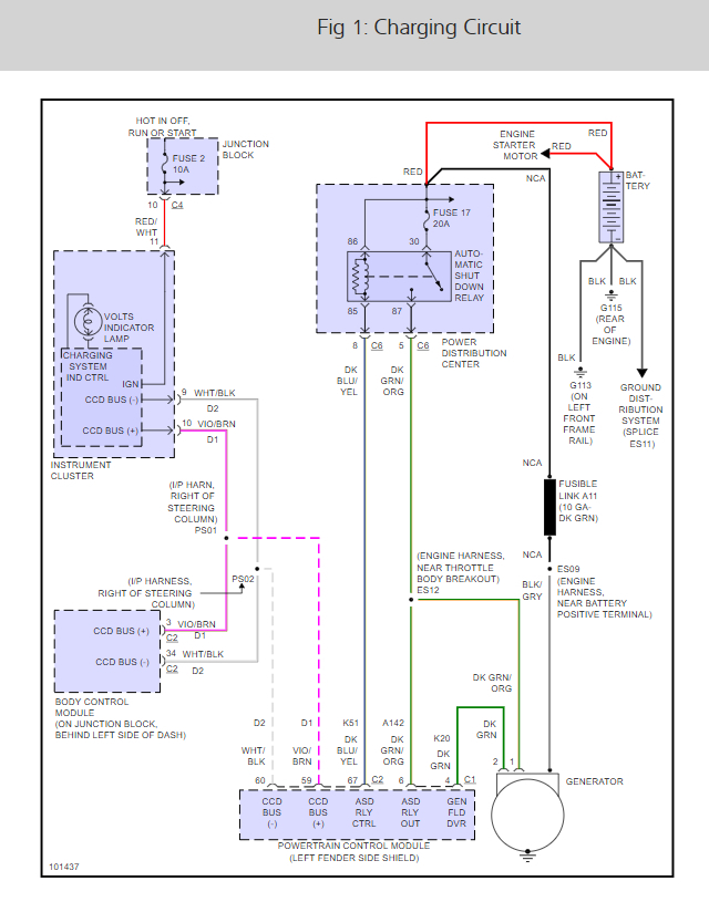
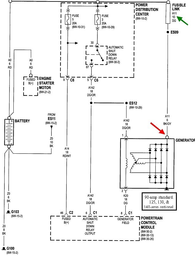
The next problem is most of these diagrams only show what is relevant to the specific circuit. You could have multiple fuse link wires bolted to that connection, but the one for the alternator does not go to the Engine Computer. It goes straight to the alternator's output terminal.

There is no need to even have to know where that fuse is unless testing proves otherwise. Just measure the voltage on the alternator's output stud. It should have full battery voltage all the time. If it does, you're done in that circuit.

Forget the ASD relay. It's true that it sends current to the alternator's field winding, but it also powers the ignition coil pack and injectors. If the engine runs, the ASD relay is turning on. Less than ten seconds to eliminate those two circuits.

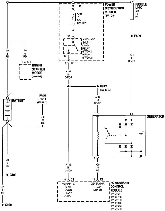
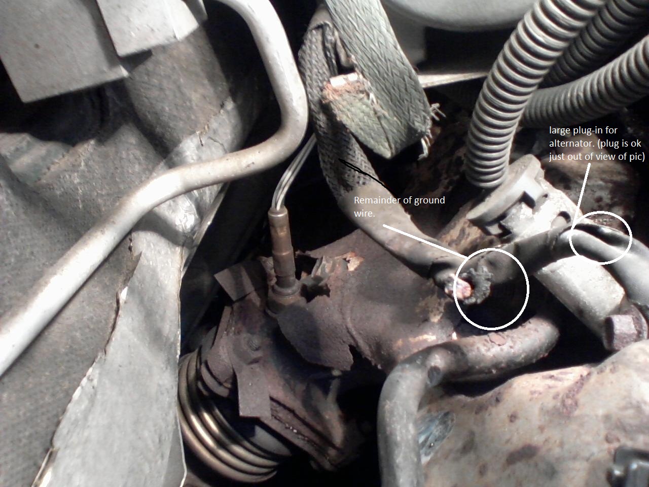
It is also correct the voltage regulator lives inside the Engine Computer, but it is incapable of being damaged by the alternator. They put it there to simplify the circuitry needed to provide information used to modify the target charging voltage. That can include wide-open-throttle, turning on the AC compressor, engine running too hot, ambient air / battery temperature real cold, etc. It is possible for the regulator circuit to fail, but it's not very common. I've only run into one since 1990. That low-current circuit is also real easy to test. Look at the two smaller terminals bolted to the back of the alternator. The engine must be running for them to have voltage from the ASD relay. One will have full battery voltage. The other one must have less, but not 0 volts. If you find 0 volts, the brushes are worn. (Nine bucks for a replacement assembly). If you find exactly the same voltage on both terminals, there is a break after that point. That could be the voltage regulator is open, but it is much more likely there's a corroded terminal in the connector going to it.

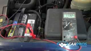
Typically you'll find between 4-11 volts on the second terminal. The lower the voltage, the greater the difference there is across the two of them, and the larger the electromagnetic field is. That one voltage will tell you if the low-current input circuit, including the voltage regulator, is working.
Was this
answer
helpful?
Yes
No
+7
Tuesday, February 21st, 2017 AT 8:09 PM
Tiny
STEVE W.
  • MECHANIC
  • 12,978 POSTS
Looking it up by VIN wouldn't matter. The wiring doesn't change for the charging system based on the option package for the Caravan.
The accident it was in however could easily have changed that. Whoever repaired it probably decided that a straight run of 10 gauge green fuse link was easier than splicing together the wiring like the OEM part. Not uncommon. Did the PDC also get replaced at that time?

Either way, you seem to have it repaired. Good luck with it. Oh does it have the clunk in the front that they get after about 80K when the sway bar bushings wear out?
Was this
answer
helpful?
Yes
No
+3
Tuesday, February 21st, 2017 AT 8:32 PM
Tiny
GIUGGIOLA
  • MEMBER
  • 0 POST
I had this problem and had to replace the ECM cost me $140.00 for a rebuilt unit I got from eBay, all fixed, I love this site.
Was this
answer
helpful?
Yes
No
Wednesday, February 22nd, 2017 AT 12:11 PM
Tiny
CKAHRL
  • MEMBER
  • 1 POST
Steve: I have a 2000 Town and Country. I am sure the fusible link to the alternator is shot (I have reasons). Apparently, the link is right by the battery/powerthingy. But before I take the cable bundle apart, it is unclear to me what kind of link it is. Some places say 14GA others say 16GA. I saw one place where it said 10GA, which sounds way too big. Also, in the schematic you give, the fusible link says: 10GA Drk GRN. But the wire running to it says NCA. What in the world is NCA? Is the link really 10GA? Autozone has links listed as 14GA and one as 16GA with a fuse which sounds small. Does the 10GA refer to the cable, in which the 14 GA would be right?
Was this
answer
helpful?
Yes
No
Tuesday, December 10th, 2019 AT 2:16 PM
Tiny
CARADIODOC
  • MECHANIC
  • 33,743 POSTS
If you "have reasons", please share them so we can have the same confidence in your diagnosis as you do. Also, please start a new question specific to your vehicle, and be sure to include the engine size and mileage. Some diagrams are different for different engine sizes, and we look at the mileage when making some judgement calls. When you add to an old question, it was a private conversation between just a few people, and they are the only ones who will get an automated e-mail link when an addition is posted. As such, none of the other experts will see your addition or have a chance to reply. That limits the help you will receive. Your new question might also help others researching this topic.

We can try to solve your problem here, but if you need to start a new question, here's a shortcut to get you there quicker:

https://www.2carpros.com/questions/new

There were four sizes of alternators available for this model and year. The wiring harness will always be the same except for the fuse or fusible link. Those are selected at the factory for the size of the alternator being installed. In this case, all they show is a 10-gauge wire, denoted by its dark green insulation. In this diagram, the fuse link is shown way up in the top right corner with my green arrow pointing to it. The small circle on top indicates that end is bolted to the under-hood fuse box. "ES09" right below it indicates that is a soldered splice to the wire it protects. That is circuit "A11 6 BK/GR". "A" circuits are always tied right to the battery positive side. This is circuit A11. It's a 6-gauge wire with black insulation and a gray tracer, (stripe). Most commonly these fuse links are part of a larger bundle of wires, but they are left out where they can be seen.

The place to start is by measuring the voltage at the alternator's large output terminal with the engine not running. That's the red arrow in the diagram. You must find that voltage is the same as battery voltage at all times. If you find 0 volts, suspect the fuse link is burned open. It's best to check this with a test light rather than a digital voltmeter. The advantage to using a fuse link wire is they are slow-acting, so they tolerate momentary current surges. The disadvantage is when they burn open, they leave a carbon track behind, and those can conduct enough current for a digital voltmeter to pick it up and falsely show there's 12 volts at the output terminal. A test light needs current flow to operate, and sufficient current can't get through that carbon track to make the bulb light up. For that reason, test lights are more accurate in this type of circuit.

If you need a new fuse link, they can be purchased at any auto parts store. You'll get a piece about a 8" long. That is plenty to be cut to make two or three repairs. The length of the fuse link isn't important. All that matters is this is the weak link in the chain, so it will burn open before the rest of the wire overheats.
Was this
answer
helpful?
Yes
No
+2
Tuesday, December 10th, 2019 AT 3:30 PM
Tiny
KEITH HAMM
  • MEMBER
  • 1 POST
  • 1997 DODGE CARAVAN
  • 6 CYL
  • 2WD
  • AUTOMATIC
  • 165,000 MILES
The alt. Shows 90 amp with a load the battery voltage still falls to about 12.2 volts sense wire has 8.6 volts ing. Wire has full battery volts the b+ volts at computer is full battery volts running out of ideas
Was this
answer
helpful?
Yes
No
Monday, September 21st, 2020 AT 7:15 PM (Merged)
Tiny
CARADIODOC
  • MECHANIC
  • 33,743 POSTS
Is that all one sentence? Do you mean you get 90 amps during a load test or there is a sticker on it that says it's a 90 amp alternator? What are the three voltages on the three alternator wires? The two smaller ones must be measured with the engine running.

Caradiodoc
Was this
answer
helpful?
Yes
No
+1
Monday, September 21st, 2020 AT 7:15 PM (Merged)
Tiny
CAT206
  • MEMBER
  • 13 POSTS
  • 1996 DODGE CARAVAN
In removing the alternator the location of the ground wire was melted off of the back, tracing the wire back a little showed the melted other side. Need to replace the alternator and have to replace the ground wire, it is wrapped with the power wire and I need to know where it goes.
Was this
answer
helpful?
Yes
No
Monday, September 21st, 2020 AT 7:15 PM (Merged)
Tiny
DOCFIXIT
  • MECHANIC
  • 18,828 POSTS
There is no ground wire can you ID color? Think it is Black/Gray if so power feed from BATT cable through a fuesible link. That maybe what fried. Was ALT light on before?
Was this
answer
helpful?
Yes
No
+1
Monday, September 21st, 2020 AT 7:15 PM (Merged)
Tiny
CAT206
  • MEMBER
  • 13 POSTS
I am attaching a photo of what is left of the wire, I can go try to pull on it to see what color the wire sheathing is, but I didnt notice a color before.
Was this
answer
helpful?
Yes
No
Monday, September 21st, 2020 AT 7:15 PM (Merged)
Tiny
DOCFIXIT
  • MECHANIC
  • 18,828 POSTS
Yep that is power lead
Was this
answer
helpful?
Yes
No
Monday, September 21st, 2020 AT 7:15 PM (Merged)
Tiny
CAT206
  • MEMBER
  • 13 POSTS
Ok so how does one go about changing it? Is there a diagram? There is no room to work in this vehicle so it is very hard to trace the wires back
Was this
answer
helpful?
Yes
No
Monday, September 21st, 2020 AT 7:15 PM (Merged)
Tiny
DOCFIXIT
  • MECHANIC
  • 18,828 POSTS
Remove ALT see if ypou can cut insulation away. Will need to soilder a 10AMP fuselink. May end up having to replace charging loom. Have ALT tested to see if that is reason for wire frying
Was this
answer
helpful?
Yes
No
Monday, September 21st, 2020 AT 7:15 PM (Merged)

Please login or register to post a reply.

Sponsored links