Alternator not charging

Tiny
RANCHER2
  • MEMBER
  • 1976 FORD F-250
  • V8
  • 4WD
  • MANUAL
  • 200,000 MILES
This has a new Centech wiring harness installed with an AMP meter Shunt incorporated with the wiring harness. The Alternator and the external regulator are new. All wiring has been rung out to verify continuity and checks good; and the alternator is well grounded. When running, the alternator shows twelve volts. When electrical load is applied the voltage drops to eleven volts. I am at a loss here, please help.
Saturday, September 24th, 2016 AT 5:37 PM

29 Replies

Tiny
RANCHER2
  • MEMBER
  • 13 POSTS
The new regulator was installed before I replaced the old alternator. Thus I suppose the old alternator may have damaged the new regulator? The regulator has three connections A, S, F, with the A terminal having twelve volts continuous from the positive terminal on the starter solenoid. The regulators S terminal goes to the alternators Sta. Terminal. The regulators F terminal goes to the alternators Field terminal. The BAT terminal on the alternator goes to the BAT buss in the trucks fuse box. I have jumped between the A and F terminals (effectively bypassing the regulator) and the voltage reading (taken at the battery) jumps to seventeen volts.
Was this
answer
helpful?
Yes
No
Saturday, September 24th, 2016 AT 6:42 PM
Tiny
RANCHER2
  • MEMBER
  • 13 POSTS
By having the alternator produce seventeen volts when the regulator is bypassed tells me the new alternator is okay, and that perhaps the new regulator is damaged. All the wiring is correctly wired IAW Centech's wiring diagrams. I also verified each wire for continuity to double check the fuse links have not been compromised. All wiring checks good. I am leaning hard towards an inoperative voltage regulator at this point.
Was this
answer
helpful?
Yes
No
Saturday, September 24th, 2016 AT 6:52 PM
Tiny
CJ MEDEVAC
  • MECHANIC
  • 11,004 POSTS
Maybe clean the connections well (the connectors on the regulator and the harness), do a little tweaking (slight bending) so that the connectors mate up well with the mating surfaces.

Sometimes time and heat sort of disfigure plastic stuff, even new stuff may be warped a little.

Check voltage "off" and "running" at the battery positive and negative posts with a voltmeter.

Return with good news!

The Medic
Was this
answer
helpful?
Yes
No
-1
Saturday, September 24th, 2016 AT 9:43 PM
Tiny
RANCHER2
  • MEMBER
  • 13 POSTS
The battery voltage with the engine off is 12.3 volts. With the engine running the battery voltage is 12.3 volts. When I apply an electrical load (turning on the headlights with the engine running) the battery voltage drops to 11.3 volts. I have double checked all alternator and regulator connections, and verified with a digital test meter the continuity. All electrical connections are good including the grounding of the alternator case.
Was this
answer
helpful?
Yes
No
Sunday, September 25th, 2016 AT 4:29 AM
Tiny
HMAC300
  • MECHANIC
  • 48,601 POSTS
Battery voltage should be 12.4 with a digital meter with everything off so battery may be weak which will cause poor charging. Also check belt is tight. Check at starter relay for a bad fuse or fusible link there it will be a different color and may not be powering up regulator. They are available at auto parts it should have battery voltage on both sides.
Was this
answer
helpful?
Yes
No
Sunday, September 25th, 2016 AT 8:31 AM
Tiny
RANCHER2
  • MEMBER
  • 13 POSTS
- I doubt that a (.1) battery voltage difference will result in the inability of the alternator to charge the battery. However as I'm grasping at straws here, I'm currently topping off the battery's charge.

- I checked the alternator belt and it is tight.

- As for the starter solenoid, the only fusible link attached to the starter solenoid is routed between the positive (positive) side of the solenoid and the battery buss in the trucks fuse box.

- I have tested all the alternator, regulator and starter solenoid's associated wiring for continuity, and it all checks good. Thus telling me the fusible links are good.

- I have attached a scan of Centech's wiring diagram for the alternator for your reference.

- Please understand I am an aircraft mechanic by trade and have a very good grasp on electrical troubleshooting. That said I am completely stumped here. I am desperate enough to use an online help forum to aide me in getting this fixed. If you guys lead me to the fix before I figure it out, I will make a financial contribution to your site out of pure gratefulness.
Was this
answer
helpful?
Yes
No
Sunday, September 25th, 2016 AT 9:39 AM
Tiny
RANCHER2
  • MEMBER
  • 13 POSTS
- Everything thus far is pointing to a bad Voltage Regulator

- When I jump the Voltage Regulator electrical connector (The connector attached to the wiring harness going to the alternator from the regulator) terminals A to F, the Alternator charges the system with seventeen plus volts.

- My question is why is the Alternator putting out seventeen plus volts when the battery terminal of the alternator is still connected between the alternator and the twelve volts battery buss at the fuse box?

- I understand that by jumping A -F I am putting twelve volts to the alternator's field, thus causing the Alternator to produce a charge above twelve volts.

- All that said, I assumed that the wire attached to the battery terminal on the alternator (which is more or less directly connected to the positive side of the battery) would provide enough resistance to limit the alternator from charging above thirteen to fourteen volts?
Was this
answer
helpful?
Yes
No
Sunday, September 25th, 2016 AT 10:39 AM
Tiny
HMAC300
  • MECHANIC
  • 48,601 POSTS
Just for pure joy have you tried disconnecting the shunt/fusible link and wiring the battery to the solenoid like it is supposed to be? I know what you have put in is supposed to be a safety link but try it like that before thinking your regulator is bad. Although it may be. Also the.1 volt is minimal because volt meters can be off as well. Because I used to work in a Ford dealer many years ago I happened to have a factory manual on hand, do not know why I kept the darn things. But anyhow if you originally had a or have a light in truck and now a re putting an amp gauge in they are wired different from the alternator. I am sending both circuits so you can see and maybe helpfully fix your problem. It may still be a voltage regulator problem, but try removing the shunt to see if it will charge then you can see these circuits they are in jpg.
Was this
answer
helpful?
Yes
No
Sunday, September 25th, 2016 AT 11:38 AM
Tiny
RANCHER2
  • MEMBER
  • 13 POSTS
- Okay, I think I am getting closer to figuring it out.

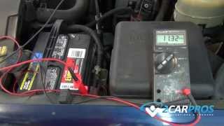
- With the battery at 100% (battery voltage 13.05v) I started the engine.
- The battery voltage dropped to 12.65v with the engine running (The alternator was not charging.)
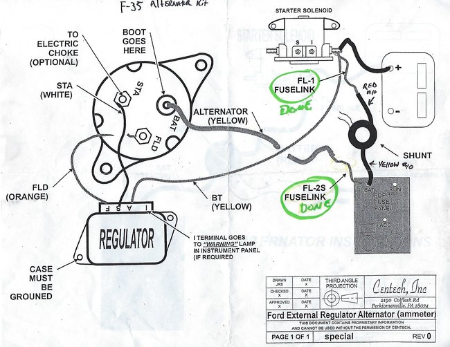
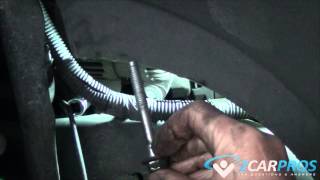
- I then jumped from the Stator terminal on the alternator to the positive post on the battery.
- As soon as the connection was made the alternator started charging at fourteen volts.
- After removing the jumper wire the alternator maintained a charge at fourteen volts

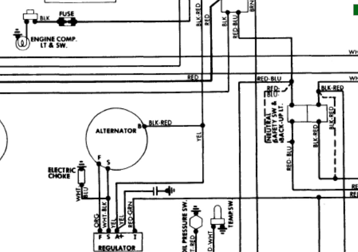
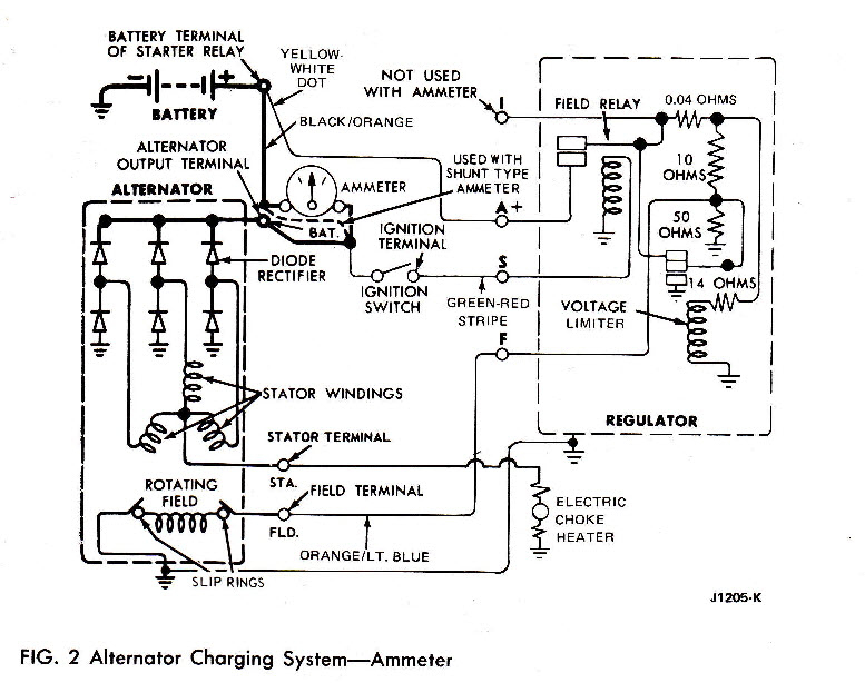
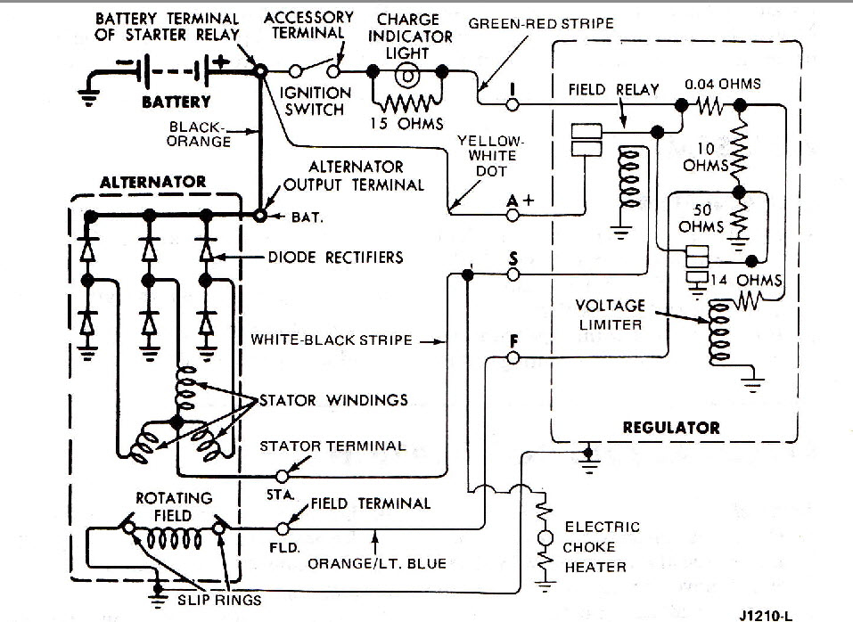
- Now I need to figure out how to excite the Stator terminal on the Alternator.
- I would assume the voltage regulator should take care of exciting the Stator terminal?

- All that said I thought that the voltage regulator applied twelve volts to the field wire going to the alternator and that is what tells the alternator to come on line?

- Thought the Stator. Was merely for sending the signal to the voltage regulator to initiate twelve volts to the field terminal on the alternator, thus bringing the alternator online and charging the battery?
Was this
answer
helpful?
Yes
No
Sunday, September 25th, 2016 AT 11:51 AM
Tiny
RANCHER2
  • MEMBER
  • 13 POSTS
- I just read your reply.
- With what I have seen with jumping the alternators (Sta.) To the battery's positive and resulting in the alternator charging, do you think removing the fusible link will have any effect?
- It appears that whatever signals the alternator to come online is not doing its job.
Was this
answer
helpful?
Yes
No
Sunday, September 25th, 2016 AT 12:04 PM
Tiny
HMAC300
  • MECHANIC
  • 48,601 POSTS
I think the shunt is your problem with the fusible link in it. And I said then to try it with that off just for the heck of it. The two diagrams I sent one was for amp gauge and other for a light and they are wired different those are straight out of a factory manual. So either the shunt is messed up or something in the wiring of that system.
Was this
answer
helpful?
Yes
No
Sunday, September 25th, 2016 AT 12:27 PM
Tiny
RANCHER2
  • MEMBER
  • 13 POSTS
- I removed the shunt along with its fusible links and wired the system IAW the Ford dwg. No joy.

- I bought another new voltage regulator and actually read the directions before installing it.

- The directions say to ohm out the voltage regulators connector "F" terminal to ground.

- If the ohm reading is less than 2.5 ohms check for a short in the alternator.

- My reading was 0 ohms and checking the alternator confirmed it was shorted between the alternator's "F" terminal and ground.

- I am hoping that another new alternator and voltage regulator together will solve this mess.

- My assumption is I burned up the last new volt reg with the original alternator. Then burned up the new alternator with the now damaged voltage regulator. Or perhaps one or both parts were defective from the get go.

- I have attached Centechs ignition wiring diagram for reference.

- If Centechs wiring diagrams were better integrated between the ignition and alternator systems perhaps it would be easier to troubleshoot.

- To be continued.
Was this
answer
helpful?
Yes
No
Sunday, September 25th, 2016 AT 4:36 PM
Tiny
RANCHER2
  • MEMBER
  • 13 POSTS
I had the alternator tested at the local auto parts shop. It tested good.

I'm contacting Centech and inquiring about this issue.

I'll keep you posted with the results.
Was this
answer
helpful?
Yes
No
Sunday, September 25th, 2016 AT 7:29 PM
Tiny
HMAC300
  • MECHANIC
  • 48,601 POSTS
Ok thanks but like I said before the amp guage and lite are both wired different on a factory setup so i'm assuming you have a lite to begin with as ford amp gauges were for crap back then
Was this
answer
helpful?
Yes
No
Monday, September 26th, 2016 AT 6:52 AM
Tiny
RANCHER2
  • MEMBER
  • 13 POSTS
Centech informs me they have seen this problem before usually on older Bronco's.

They said the Alternator is not putting out enough voltage to signal the regulator to ask for more voltage from the alternator.

They told me to run a wire from the ACC buss in my fuse box to the alternator's "S" terminal.

Doing so will effectively provide 12v to excite the Regulators "S" terminal only when the ignition switch is in the run position.

Seems kinda hoaky to me, but I'll give it a go and see what happens.

I'll post the results.
Was this
answer
helpful?
Yes
No
Monday, September 26th, 2016 AT 5:33 PM
Tiny
KEN L
  • MASTER CERTIFIED MECHANIC
  • 42,895 POSTS
I had a thought, do you have a good ground from the engine to the frame? This could cause a problem if you do not.
Was this
answer
helpful?
Yes
No
Monday, September 26th, 2016 AT 10:20 PM
Tiny
HMAC300
  • MECHANIC
  • 48,601 POSTS
One other thing when I did ford alternators years ago they would charge but not pick up a load, meaning if you turned h eadlights on it would discharge and I forget wha the problem was but it seemed to be alternator which you have had tested and it does well. So i' would imagine to go make sure ground is good battery to engine and frame like ken sais.
Was this
answer
helpful?
Yes
No
Tuesday, September 27th, 2016 AT 7:15 AM
Tiny
RANCHER2
  • MEMBER
  • 13 POSTS
Yes the alternator is well grounded as I checked the continuity between the negative post on the battery and the alternator's case and it was good.

A retired Ford mechanic tells me that Ford did in fact run a switched 12v wire to the "S" terminal on the voltage regulator.

I checked the old wiring harness I removed from the truck, and could not find evidence that my truck was wired that way.

I'll have to decide where to run the switched 12v wire to.

I'm leaning on running the wire directly to the alternator's "S" terminal to eliminate any wire splices.
Was this
answer
helpful?
Yes
No
Tuesday, September 27th, 2016 AT 6:09 PM
Tiny
RANCHER2
  • MEMBER
  • 13 POSTS
Problem resolved.

I removed the Stator wire between the alternator and voltage regulator.

I then ran a wire from the ignition buss in the vehicle's fuse box to the "S" terminal on the voltage regulator.

Luckily the new Centech fuse box had several extra fused terminals on the ignition buss. I simply wired into a 15 amp fused terminal & ran the wire to the voltage regulator's "S" terminal.

I fired up the truck and the alternator was charging as advertised at 14.3v.

Now I can get back to working the ranch instead of playing truck mechanic.
Was this
answer
helpful?
Yes
No
Friday, September 30th, 2016 AT 8:15 PM
Tiny
HMAC300
  • MECHANIC
  • 48,601 POSTS
I thought the one diagram I sent to you showed the wire going to the s terminal on voltage regulator. Least it's fixed that's the important part.
Was this
answer
helpful?
Yes
No
Saturday, October 1st, 2016 AT 7:24 AM

Please login or register to post a reply.

Sponsored links