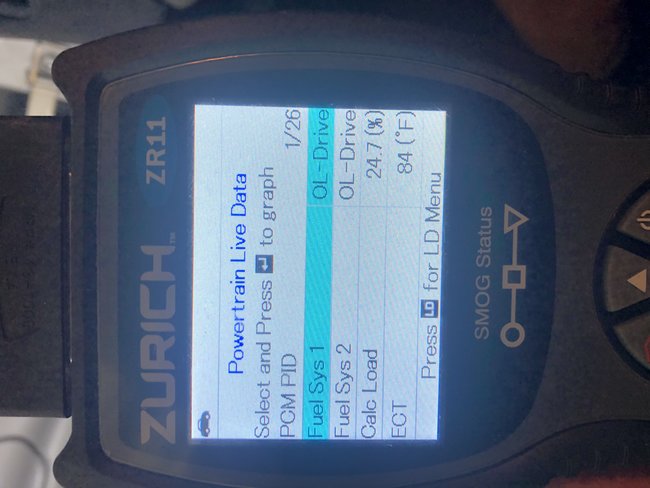
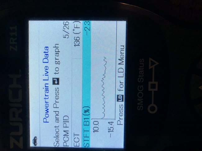
Hi,
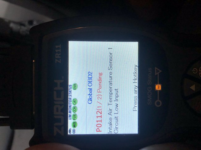
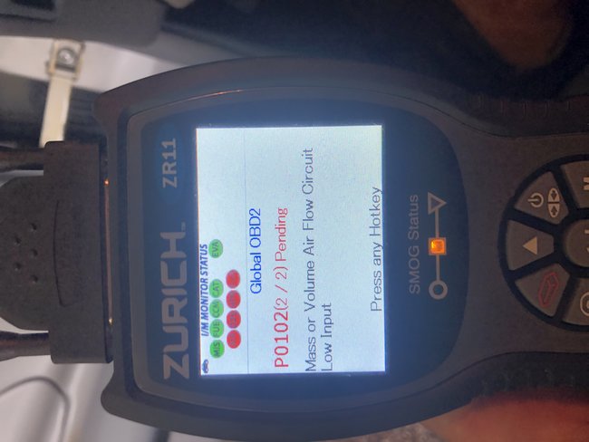
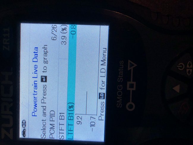
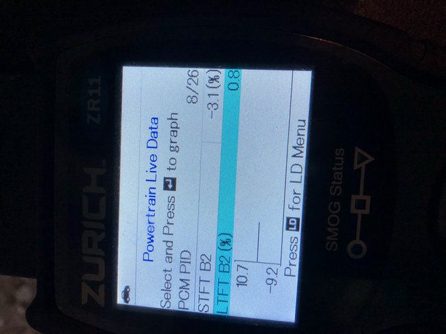
The computer is adding fuel which could indicate a vacuum leak. However, it really isn't what I consider out of range. Now interestingly, the codes you provided both indicate low
voltage. This can be the problem you are experiencing. It could be a poor connection to the sensors (corrosion) an open circuit, or a short to ground.
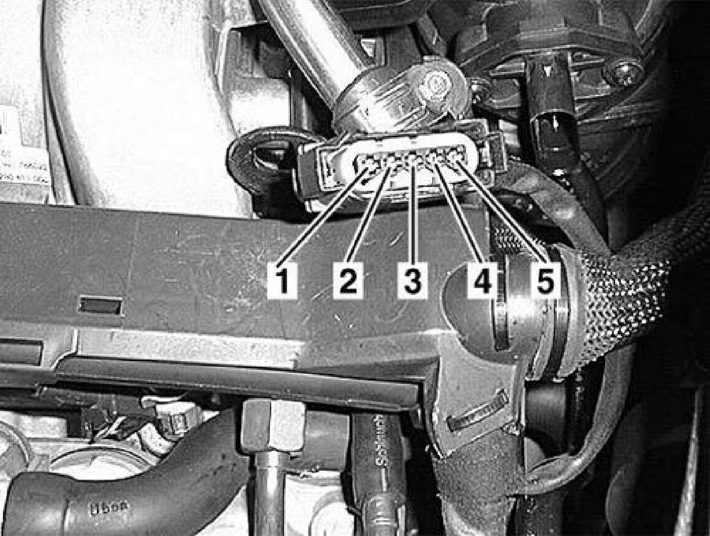
Interestingly on your vehicle, the intake air temperature sensor is integral with the MAF. So, we need to diagnose the MAF to see where the problem is originating. And yes, I feel this has at least a hand in the stalling issue.
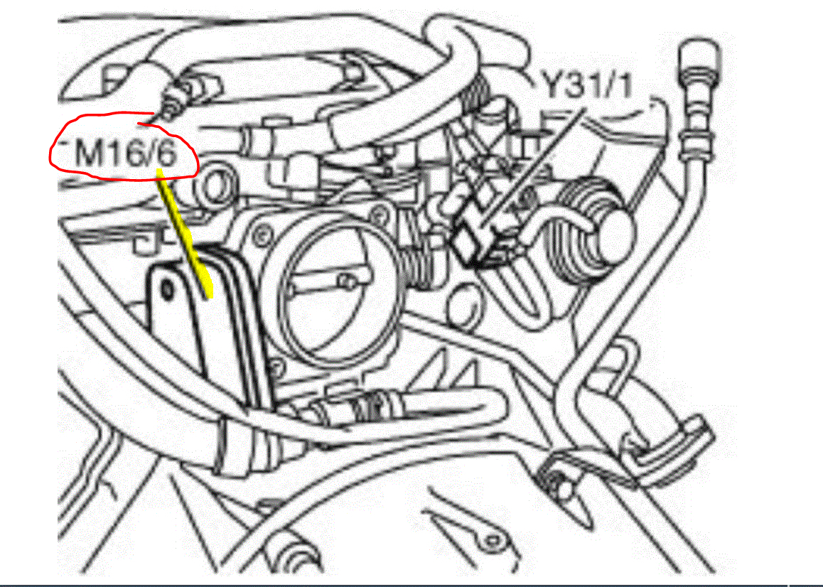
Here is the diagnostic flow chart to check power at the plug. Before you go to this extent, make sure the connection is clean and nothing is stopping power from flowing.
____________________________________
This is a bit involved, so feel free to let me know if I can help. The attached pictures correlate with these directions.
___________________________________
2002 Mercedes Benz C 320 Sedan (203.064) V6-3.2L (112.946)
B2/5 (Hot Film MAF Sensor) : Short Circuit to Ground or Open Circuit
Vehicle ALL Diagnostic Trouble Codes ( DTC ) Testing and Inspection P Code Charts P0102 B2/5 (Hot Film MAF Sensor) : Short Circuit to Ground or Open Circuit
B2/5 (HOT FILM MAF SENSOR) : SHORT CIRCUIT TO GROUND OR OPEN CIRCUIT
B2/5 (Hot Film MAF Sensor) : Short Circuit to Ground or Open Circuit (P0102)
Check component B2/5 (Hot Film MAF Sensor).
Test 1 Test Signal Voltage of Component B2/5 (Hot Film MAF Sensor) By Means Of Actual Value.
Test 2 Test Voltage Supply of Component B2/5 (Hot Film MAF Sensor).
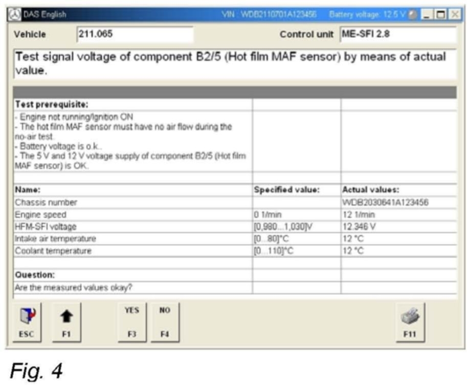
1 Test Signal Voltage of Component B2/5 (Hot Film MAF Sensor) By Means Of Actual Value.
Test requirement
- Battery voltage is o.K.
- The 5 voltage supply of component B2/5 (Hot film MAF sensor) is OK.
- The 12 voltage supply of component B2/5 (Hot film MAF sensor) is OK.
- Engine not running
- Ignition ON
Status of relevant actual value:
- HFM-SFI voltage: Note! Communication with ECU required
Specified value:
- Voltage [0,980.1,030] V
Question
- Are the measured values okay?
Yes
The actual values are okay.
Possible cause and remedy
- Check assignment of component B2/5 (Hot film MAF sensor) to engine model designation.
No
The measured values are not o.K.
Possible cause and remedy
- Test voltage supply of component B2/5 (Hot film MAF sensor).
- Inspect cables from component N3/10 (ME-SFI control module) to component B2/5 (Hot film MAF sensor).
- B2/5 (Hot film MAF sensor)
** End of Test **
2 Test Voltage Supply of Component B2/5 (Hot Film MAF Sensor).
Testr 2-1 Test Voltage Supply 5V of Component B2/5 (Hot Film MAF Sensor).
Test 2-2 Test Voltage Supply 12V of Component B2/5 (Hot Film MAF Sensor).
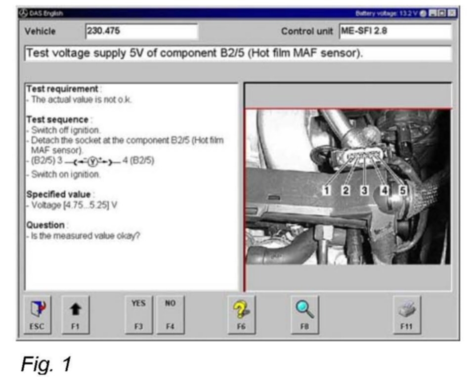
2-1 Test Voltage Supply 5V of Component B2/5 (Hot Film MAF Sensor).
Pic 1
Test requirement
- The actual value is not o.K.
Test sequence
- Switch off ignition.
- Detach the socket at the component B2/5 (Hot film MAF sensor).
- (B2/5) 3 4 (B2/5)
- Switch on ignition.
Specified value
- Voltage[4.75.5.25] V
Question
- Is the measured value okay?
Yes
The measured value is o.K. ** End of test **
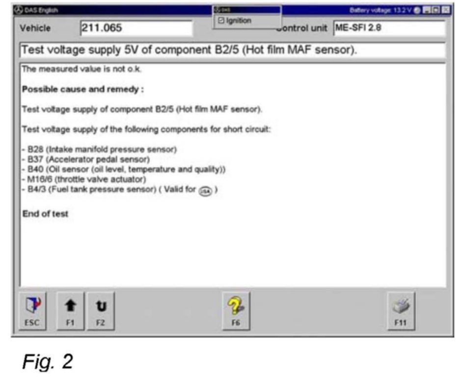
No
The measured value is not o.K. Possible cause and remedy : Test voltage supply of component B2/5 (Hot film MAF sensor). Test voltage supply of the following components for short circuit:
- B28 (Intake manifold pressure sensor)
- B37 (Accelerator pedal sensor)
- B40 (Oil sensor (oil level, temperature and quality))
- M16/6 (throttle valve actuator)
- B4/3 (Fuel tank pressure sensor)(only )
** End of Test **
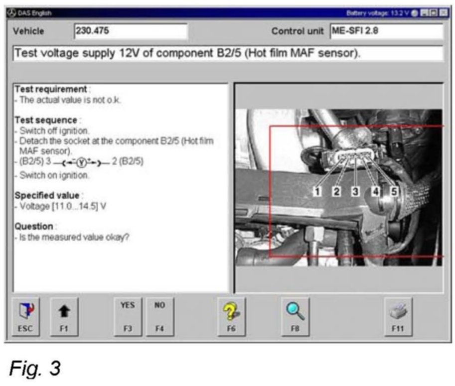
2-2 Test Voltage Supply 12V of Component B2/5 (Hot Film MAF Sensor).
Pic 2
Test requirement
- The actual value is not o.K.
Test sequence
- Switch off ignition.
- Detach the socket at the component B2/5 (Hot film MAF sensor).
- (B2/5) 3 2 (B2/5)
- Switch on ignition.
Specified value
- Voltage[11.0.14.5] V
Question
- Is the measured value okay?
Yes
The measured value is o.K.
Further possible causes of fault
- Unmetered air
- Signal wire
- B2/5 (Hot film MAF sensor)
No
The measured value is not o.K.
Possible cause and remedy
- Cable for voltage supply
________________________________________
I wanted to add this. I found a technical service bulletin (TSB) related to MAF issues. Note that the codes you see are specific Mercedes codes and are different than the P codes the scanner indicated. However, they are the same. This TSB just shows how involved this can become and will need to be followed if we can't find an issue with the aforementioned flow chart.
________________________________________
2002 Mercedes Benz C 320 Sedan (203.064) V6-3.2L (112.946)
Engine Controls - MAF/IAT Sensor DTC Troubleshooting
Vehicle Powertrain Management Sensors and Switches - Powertrain Management Engine Controls - MAF/IAT Sensor DTC Troubleshooting
ENGINE CONTROLS - MAF/IAT SENSOR DTC TROUBLESHOOTING
Related Links
MAF Sensor/Self-Adaptation of Mixture Formation
Description of the Adaptive Mixture Control as Part of Lambda Control
MAF sensor and self-adaptation of mixture formation trouble-shooting diagram
Repair process for fault code P2004-[ ]
Functional description of the MAF sensor:
Upon engine start, a current is passed through the MAF sensor, heating the wire film to a certain temperature. As air passes through the sensor, this film is cooled and the sensor determines how much electricity is required to keep the film up to temperature. This enables the sensor to determine how much air (in weight) is passing through the sensor at any given moment. This signal is then sent to the ECU which it compares to a preprogrammed map to deliver fuel and ignition spark, taking into account other engine inputs such as engine RPM and temperature.
The air intake temperature sensor is also mounted in the mass air flow sensor.
The monitor of the MAF sensor is active after a specified time after engine start and above a specified engine speed threshold.
Pic 3
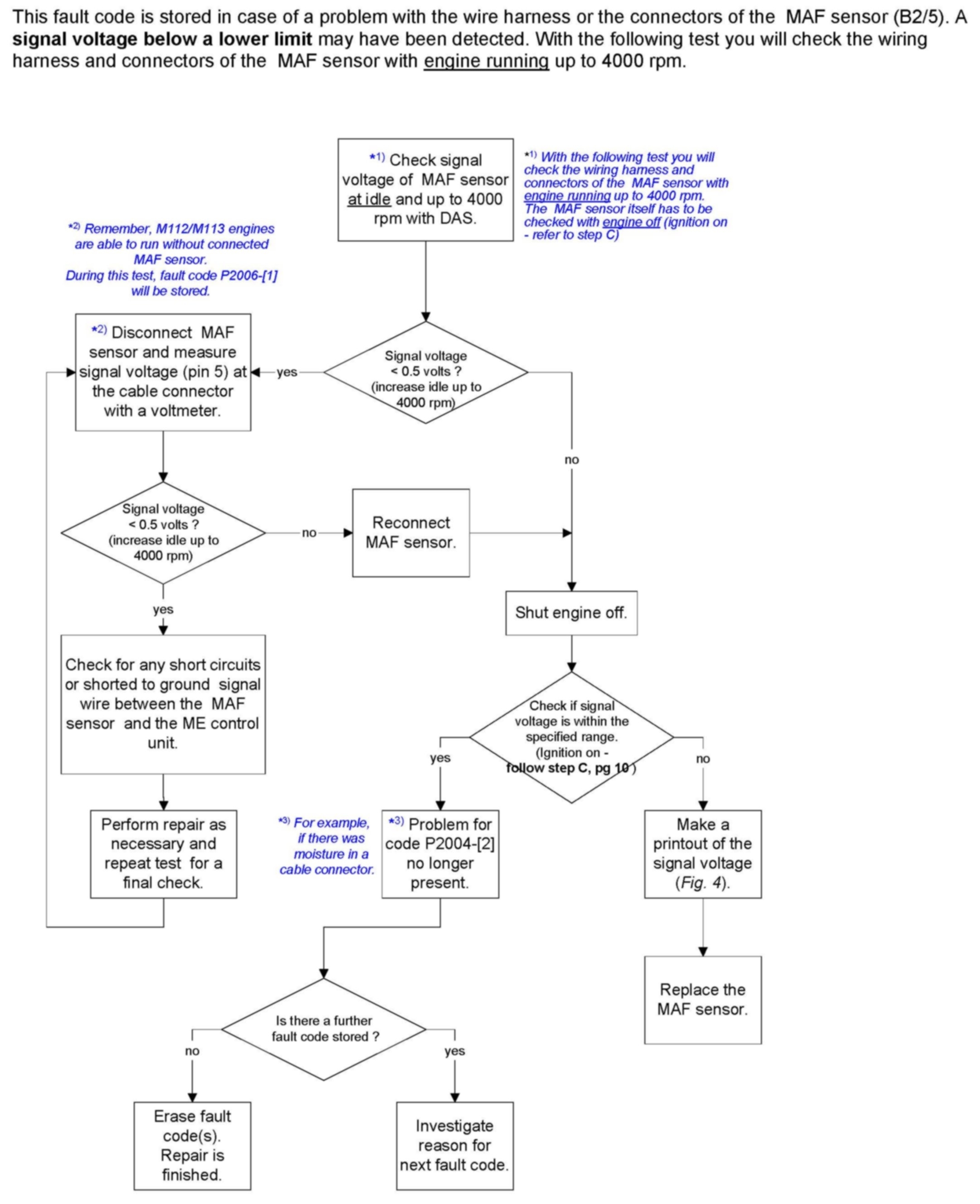
Repair process for fault code P2004-[2]
pic 4
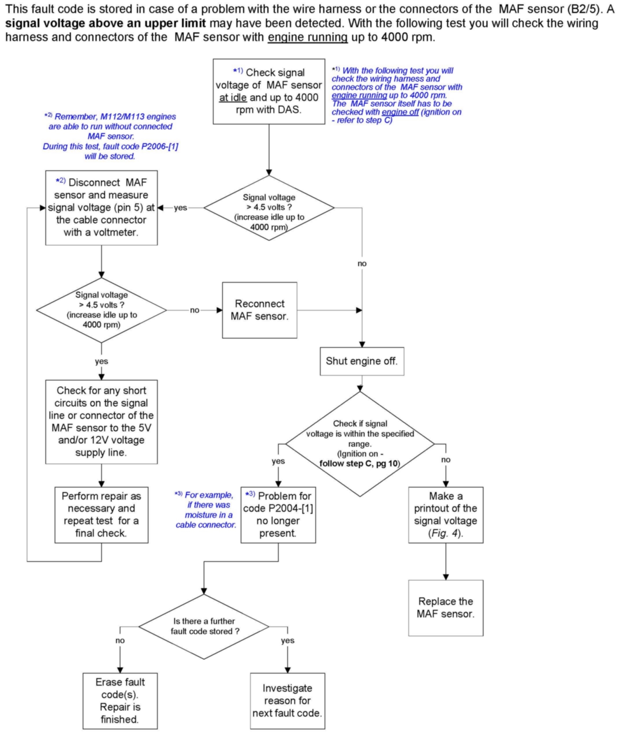
Repair process for fault code P2004-[1]
pic 5
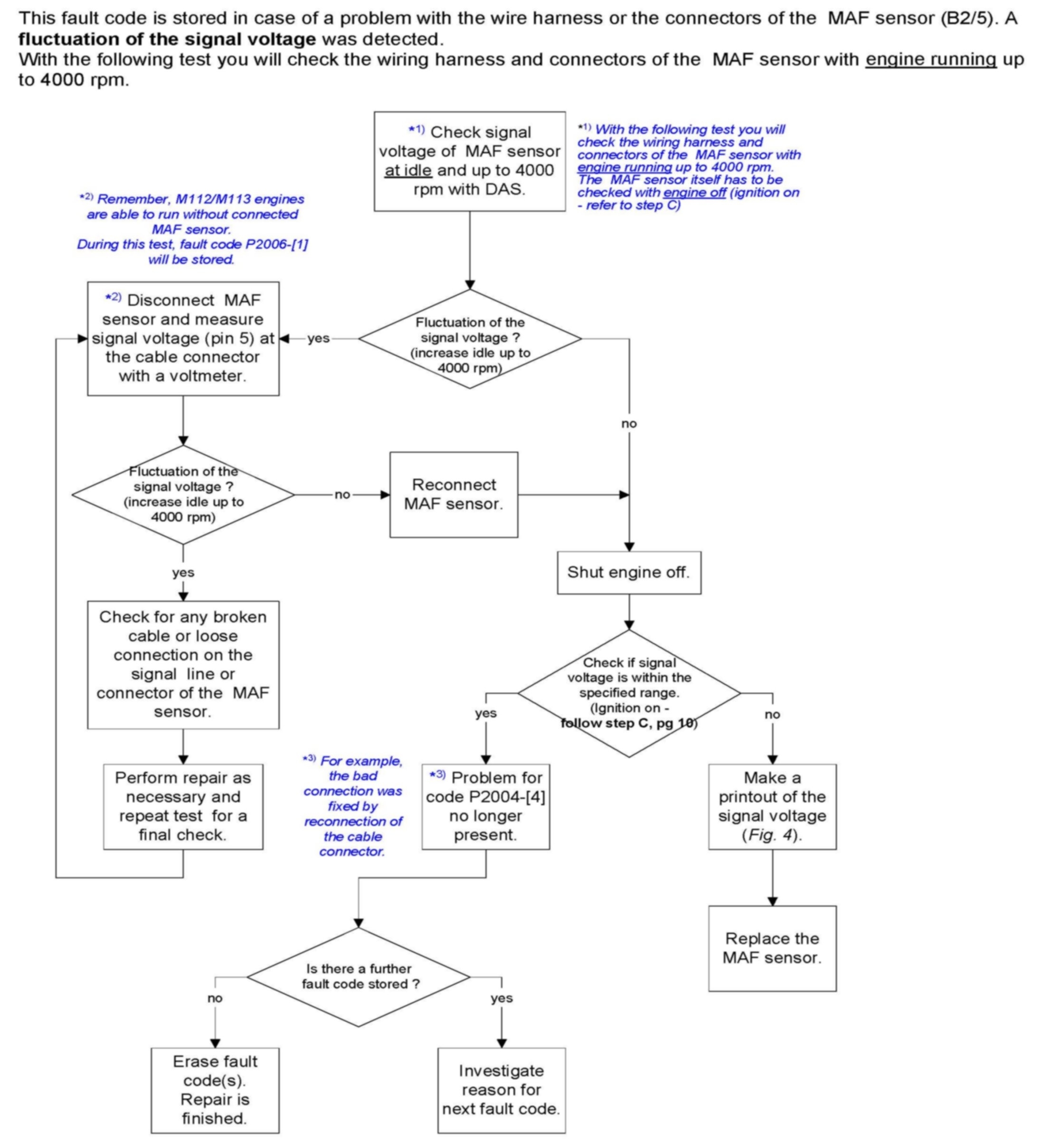
Repair process for fault code P2004-[4]
pic 6
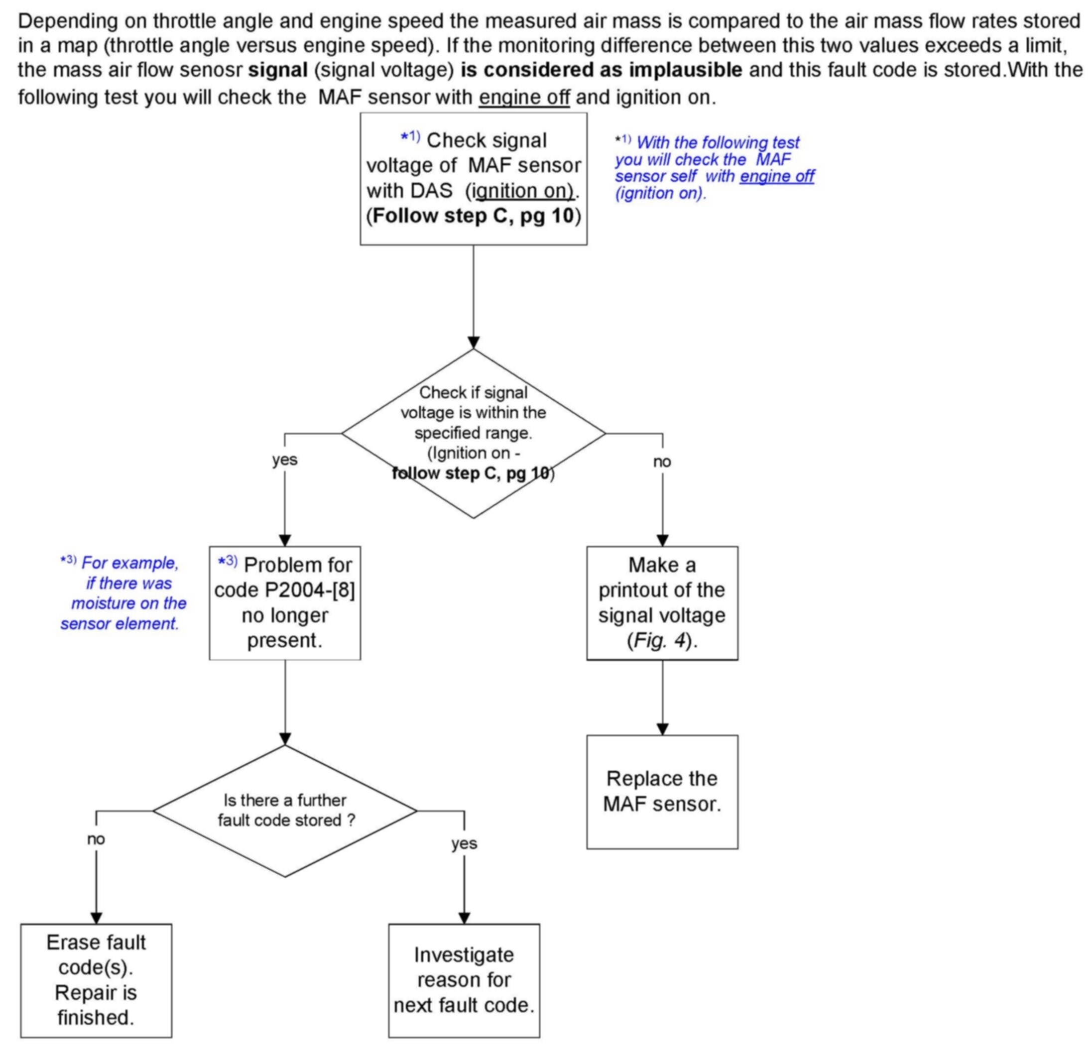
Repair process for fault code P2004-[8]
Description of test steps of remedy process fault codes P2004-[ ]
pic 7
Step A: Test voltage supply 5V of component B2/5 ( MAF sensor).
Step A1: Additionally please check the voltage supply of component B2/5 (MAF sensor) also with running engine to extend this test on higher temperature and vibration conditions of the MAF sensor.
Pic 8
Step A2: If the measured value is not O.K. Please follow the next steps shown in Fig. 2:
Step B: Test voltage supply 12V of component B2/5 ( MAF sensor).
Pic 9
Step B1: Additionally please check the voltage supply of component B2/5 (MAF sensor) also with running engine to extend this test on higher temperature and vibration conditions of the MAF sensor.
If the measured value is not O.K, check for a short circuit on the wiring or connector of the12V battery voltage cable and also the Z-connection (Z7/35) of the MAF sensor (B2/5).
Step C: Test signal voltage of component B2/5 ( MAF sensor) by means of actual value.
Pic 10
Note:
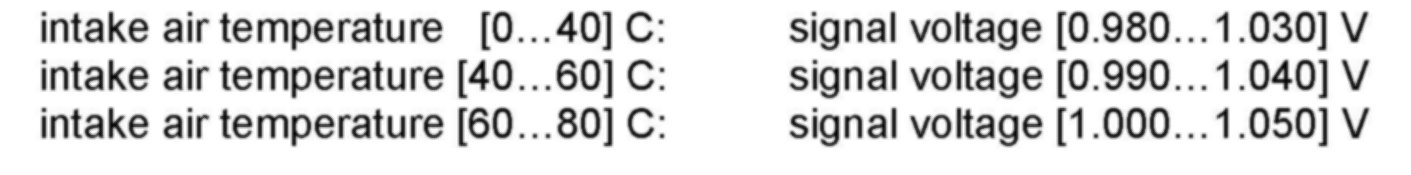
The specified value of the HFM-SFI voltage depends on the intake air temperature (B2/5b1):
pic 11
Specified value
Note:
The signal voltage test is to be done with ignition ON and engine off. If the engine speed (also shown in the screen of the signal voltage test, Fig. 4) is not 0 rpm, the specified value of the signal voltage can't be used for the signal voltage test.
Note:
In order to avoid the possibility of a false signal voltage reading please only perform the signal voltage test with the air filter housing completely assembled on the hot film MAF sensor. Also please ensure that there is no exhaust gas extraction device on the tail pipe of the vehicle. Any air flow thru the hot film MAF sensor during the signal voltage test will cause a false reading.
If the status of the relevant actual value is out of range from the specified value and all test requirements were fulfilled, replace the mass air flow sensor and send this part with the required DAS original printouts to our Quality Evaluation Center.
Note:
Before replacing the mass air flow sensor, check for sand and dirt particles in the clean side (between air filter and engine) of the air intake system and clean if necessary. Check complete air intake system with air cleaner and repair as necessary.
Required DAS-printouts for warranty returns:
Printout of all fault codes of the ME2-SFI-motor electronics (short test).
Freeze frame data of all fault codes stored in the ME2-SFI-motor electronics.
Signal voltage printout Fig. 4 (page 10) of component B2/5 (Hot film MAF sensor).
Returned MAF sensors without the required information will be debited back to the dealer.
Note:
Only original, readable printouts with the VIN number (DAS-readout) of the vehicle are accepted. The required printouts can be made only with DAS-Version starting 02/04.
Pic 12
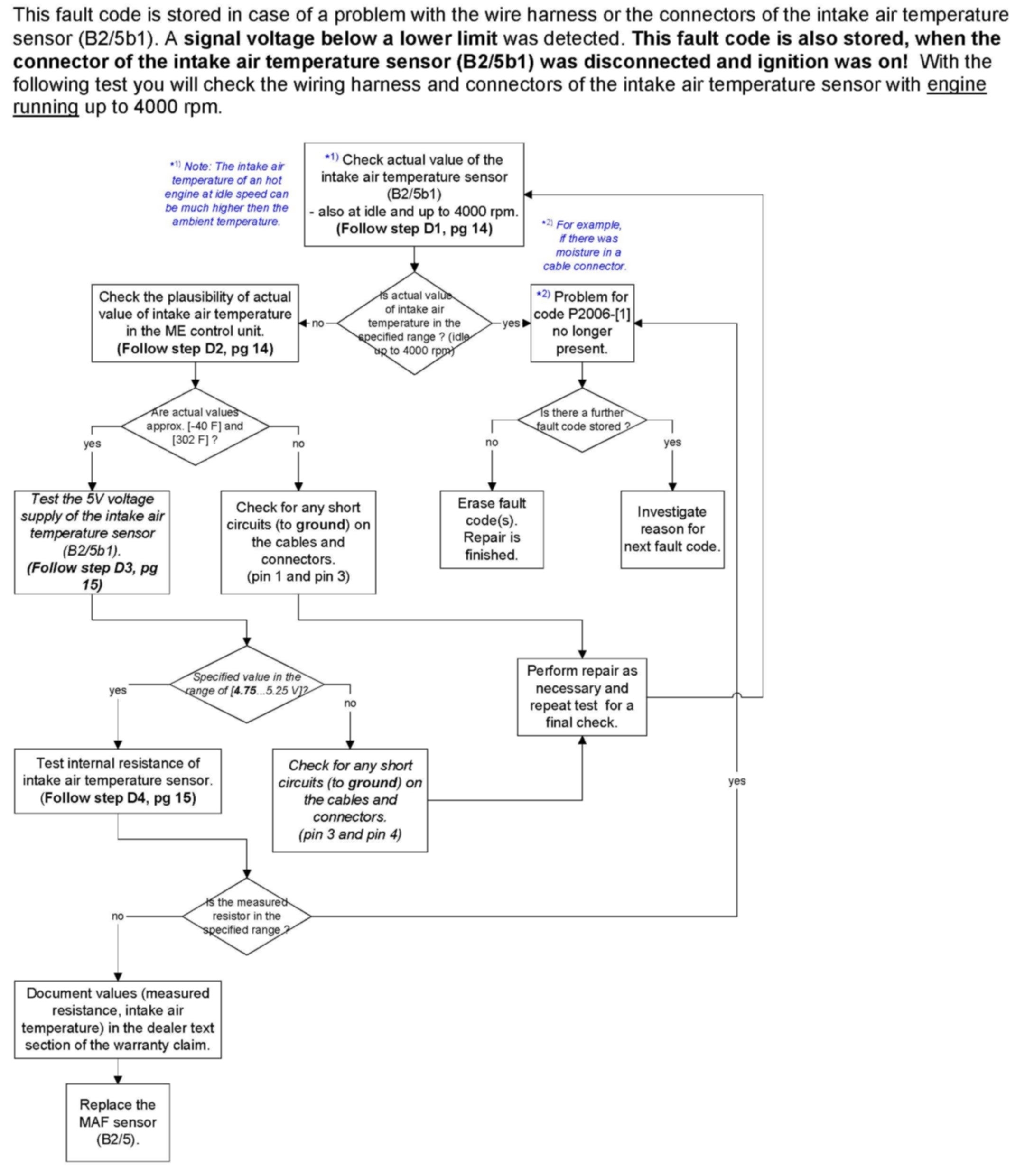
Repair process for fault code P2006-[1]
pic 13
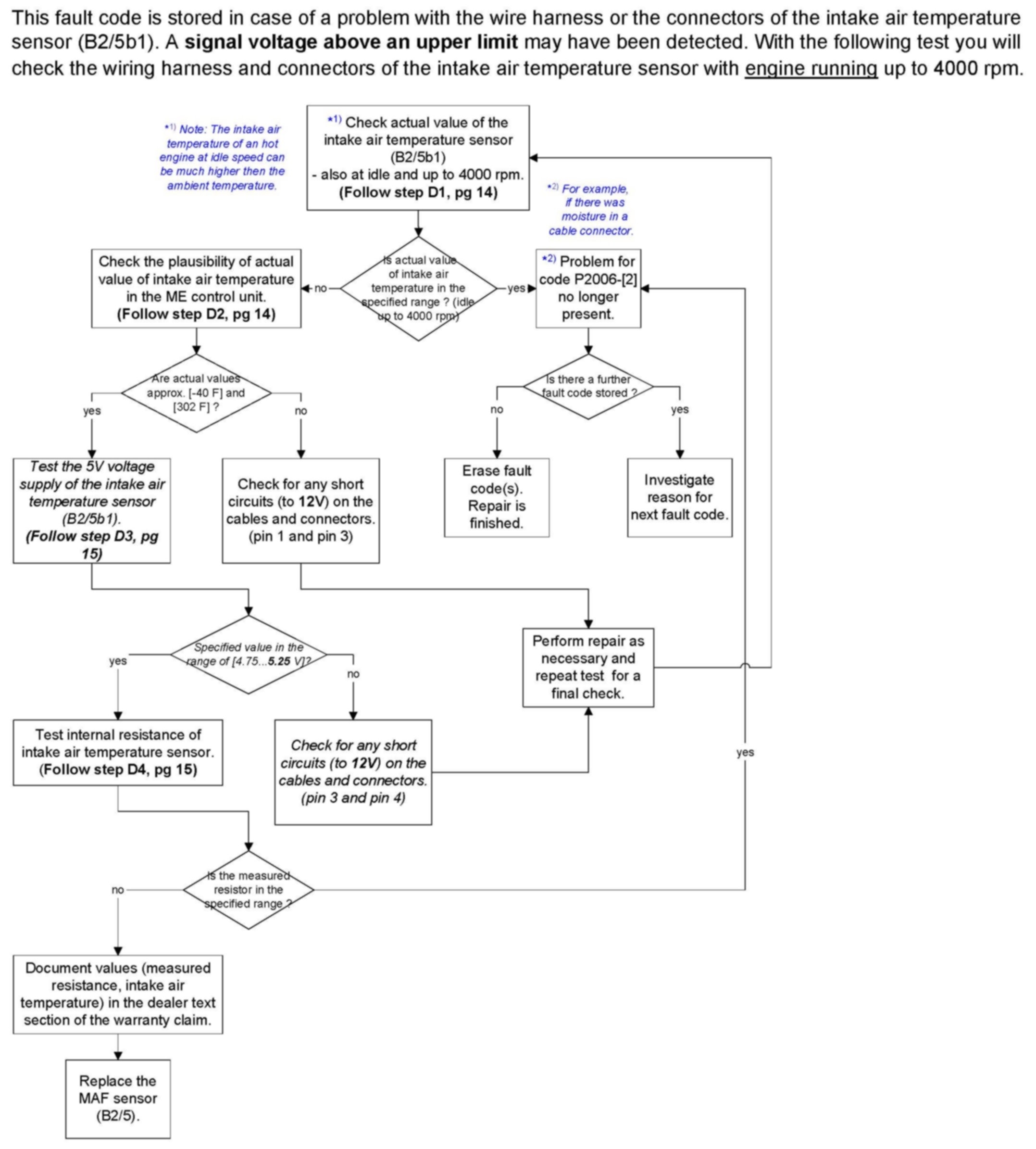
Repair process for fault code P2006-[2]
Description of test steps of remedy process fault codes P2006-[ ]
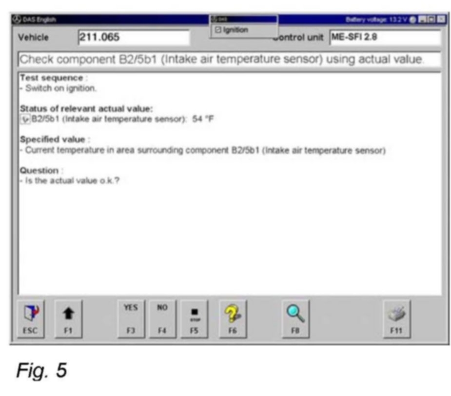
Step D1: Check component B2/5b1 (Intake air temperature sensor) using actual value.
Pic 14
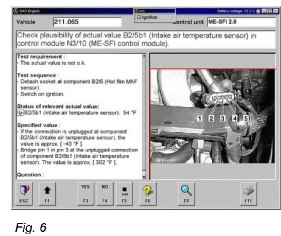
Step D2: Check plausibility of actual value B2/5b1 (Intake air temperature sensor) in control module N3/10 (ME-SFI control module).
Pic 15
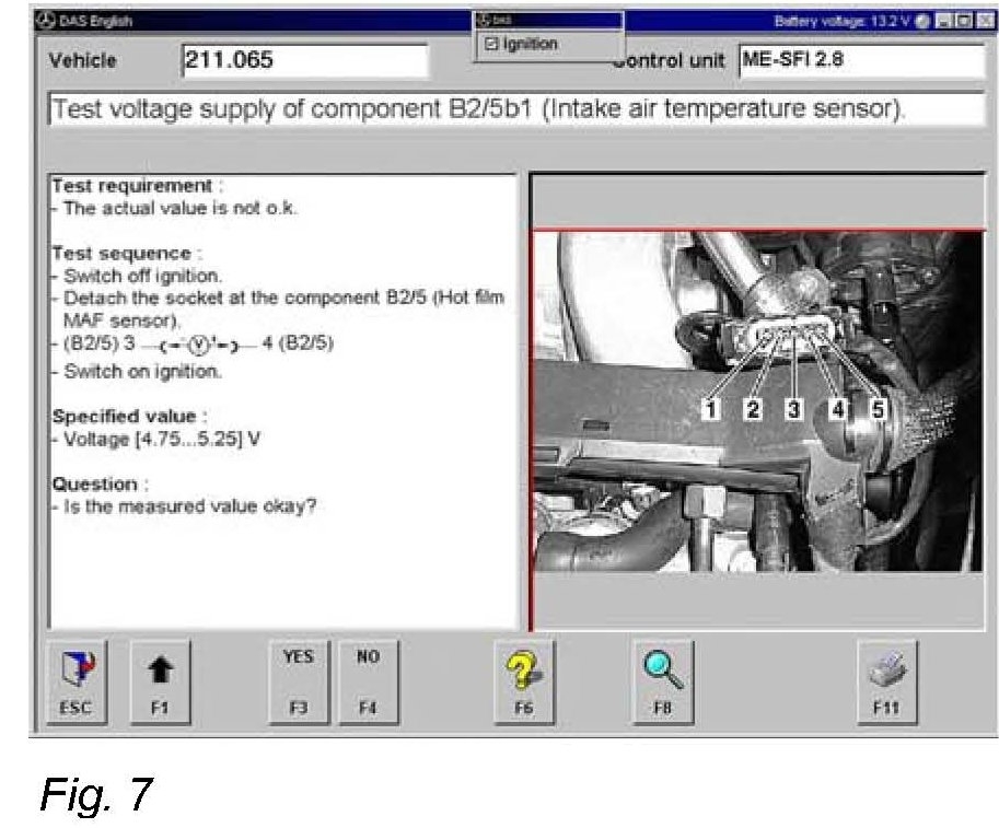
Step D3: Test voltage supply of component B2/5b1 (Intake air temperature sensor).
Pic 16
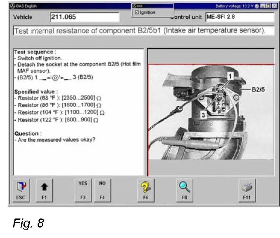
Step D4: Test internal resistance of component B2/5b1 (Intake air temperature sensor).
Pic 17
If the measured value of the resistor of the intake air temperature sensor is out of range from the specified value and all test requirements were fulfilled, replace the mass air flow sensor and send this part with the required DAS-printouts (see below) to our Quality Evaluation Center.
Note:
Before replacing the mass air flow sensor, check for sand and dirt particles in the clean side (between air filter and engine) of the air intake system and clean if necessary. Check complete air intake system with air cleaner and repair as necessary.
Required DAS-printouts for warranty returns:
Printout of all fault codes of the ME2-SFI-motor electronics (short test).
Freeze frame data of all fault codes stored in the ME2-SFI-motor electronics.
Document the value of the measured resistance and the approximate temperature of the area surrounding component B2/5b1 for test purposes in our Quality Evaluation Center in the dealer text section of the warranty claim.
Returned MAF sensors without the required information will be debited back to the dealer as of repair date March 12, 2004.
Note:
Only original, readable printouts with the VIN number (DAS-readout) of the vehicle are accepted.
_________________________________________________
Let me know if you have questions or need help.
Take care,
Joe
Images (Click to make bigger)
Sunday, April 12th, 2020 AT 8:09 PM