Hi and thanks for using 2CarPros.
Honestly, based on your description, it sounds like a bad head gasket.
The first thing we need to do is determine if a head gasket has failed. Follow the directions in the following link and let me know what you find.
https://www.2carpros.com/articles/head-gasket-blown-test
Now, if you determine it is a bad head gasket, here are the directions for replacing it. The attached pictures correlate with these directions.
CYLINDER HEAD REMOVAL AND INSTALLATION
REMOVAL PROCEDURE
1. Disconnect the negative battery cable.
CAUTION: Refer to Battery Disconnect Caution in Service Precautions.
2. Remove the intake manifold. Refer to Intake Manifold Replacement (Complete - VIN 1).
3. Remove the exhaust manifold. Refer to Exhaust Manifold Replacement (Left).
4. Remove the rocker arm cover. Refer to Valve Rocker Arm Cover Replacement (Left).
Picture 1
5. Remove the electronic ignition module.
6. Disconnect the spark plug wires.
7. Remove the generator bracket and the generator. Refer to Generator Replacement in Starting and Charging.
8. Remove the A/C compressor bracket bolt.
9. Remove the power steering pump. Refer to Power Steering Pump Replacement in Steering.
10. Remove the drive belt tensioner. Refer to Drive Belt Tensioner Replacement (VIN 1) and to Drive Belt Tensioner Replacement (VIN 1 - Supercharger).
11. Remove the fuel pipe heat shield.
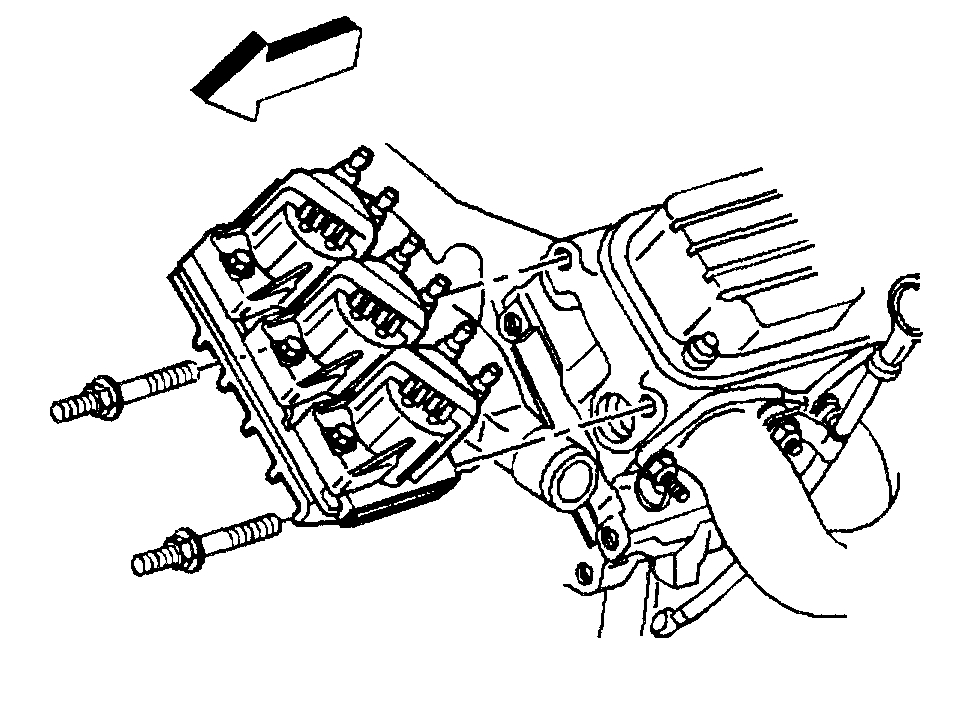
12. Remove the rocker arm assemblies and the pushrods. Refer to Valve Rocker Arm and Push Rod Replacement.
Picture 2
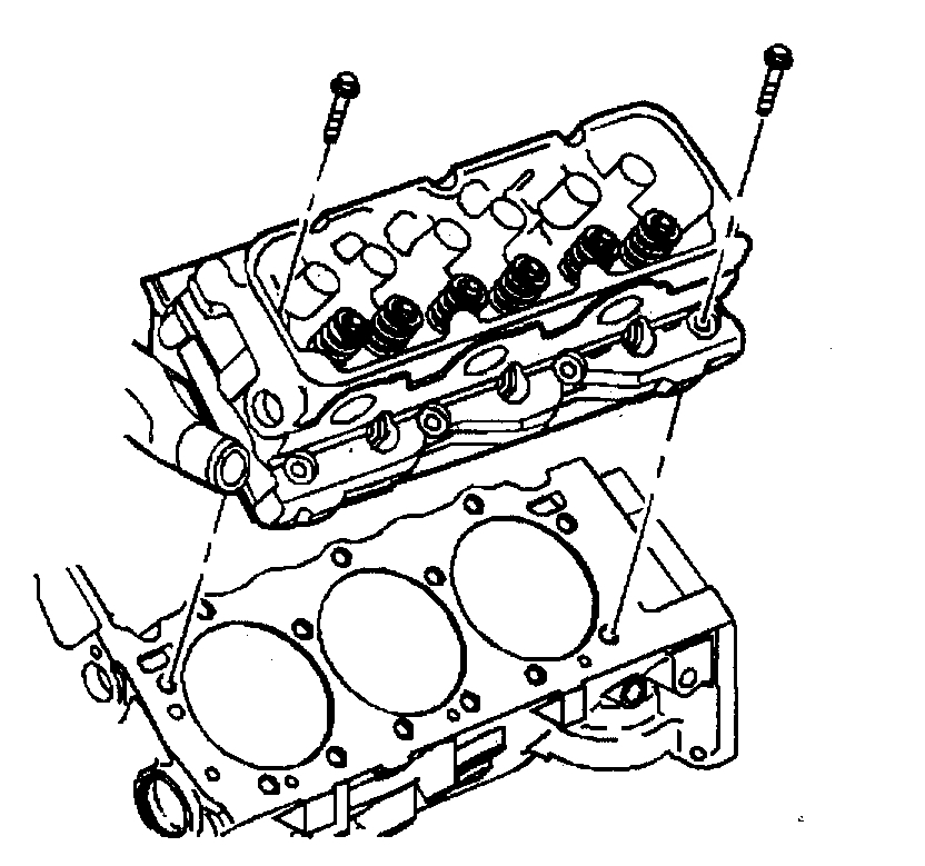
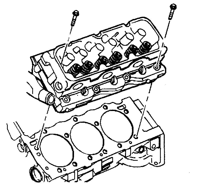
13. Remove the cylinder head bolts. Discard the bolts.
14. Remove the cylinder head.
Picture 3
15. Remove the cylinder head gasket.
16. Clean all of the gasket mating surfaces.
17. Inspect the cylinder head. Refer to Cylinder Head Clean and Inspect in Unit Repair.
INSTALLATION PROCEDURE
^ Tools Required
- J 36660 Torque Angle Meter
- 7/16-14 tap
NOTICE: This engine uses special torque to yield head bolts. This design bolt requires a special tightening procedure. Failure to follow the given procedure will cause head gasket failure and possible engine damage.
1. Clean the threads in the block. Use a 7/16-14 tap.
Picture 4
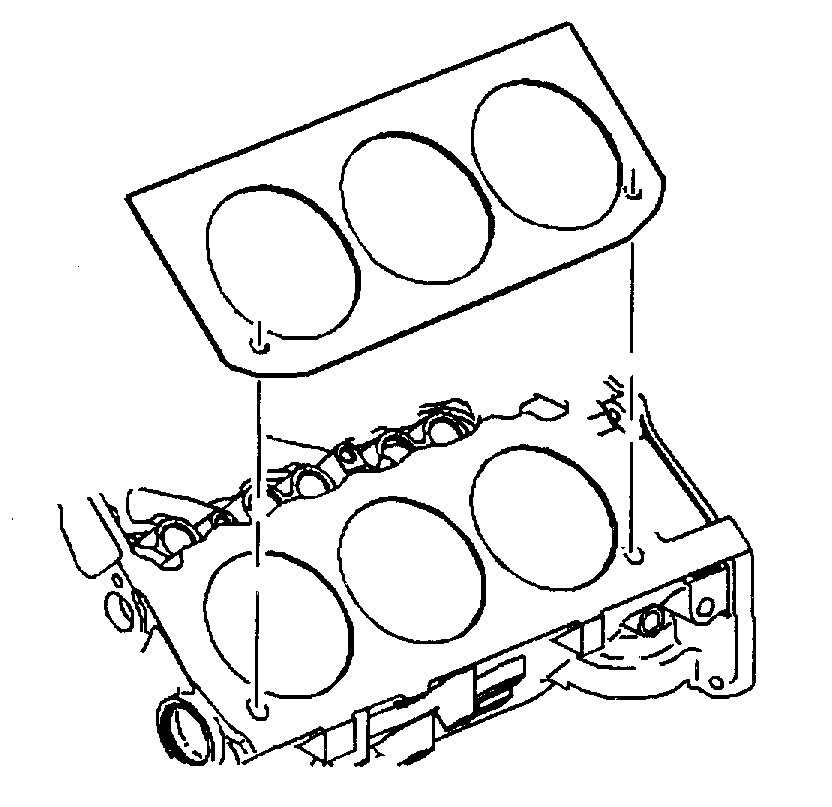
2. Install the head gasket with the arrow pointing to the front of the engine.
Picture 5
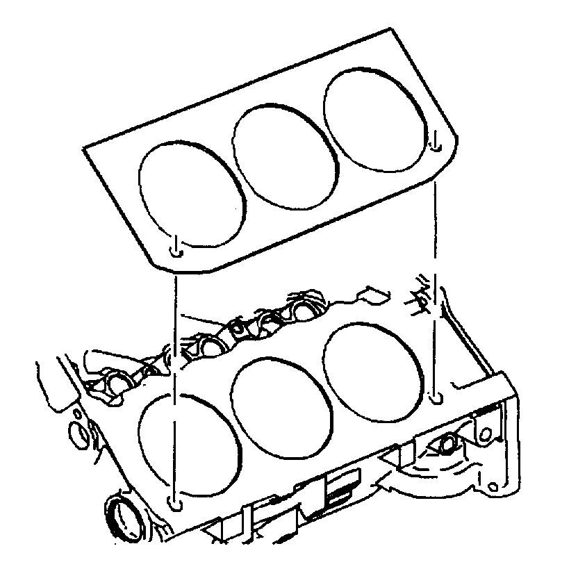
3. Install the cylinder head.
Picture 6
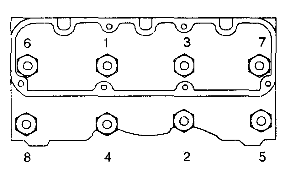
4. Install the new cylinder head bolts.
^ Tighten the bolts in sequence to 50 Nm (37 ft. lbs.).
^ Rotate each bolt 120° in sequence. Use the J 36660.
NOTICE: This bolt is designed to permanently stretch when tightened. The correct part number fastener must be used to replace this type of fastener. Do not use a bolt that is stronger in this application. If the correct bolt is not used, the parts will not be tightened correctly. The system or the components may be damaged.
NOTICE: Refer to Fastener Notice in Service Precautions.
5. Install the rocker arm assemblies and the pushrods. Refer to Valve Rocker Arm and Push Rod Replacement.
NOTICE: This bolt is designed to permanently stretch when tightened. The correct part number fastener must be used to replace this type of fastener. Do not use a bolt that is stronger in this application. If the correct bolt is not used, the parts will not be tightened correctly. The system or the components may be damaged.
6. Apply GM approved thread lock compound or equivalent to the rocker arm pedestal bolts before assembly.
7. Install the intake manifold. For the VIN 1, refer to Intake Manifold Replacement (Complete - VIN 1).
8. Install the rocker arm cover. Refer to Valve Rocker Arm Cover Replacement (Left).
9. Install the exhaust manifold. Refer to Exhaust Manifold Replacement (Left).
10. Install the A/C compressor bracket bolt.
^ Tighten the bolt to 70 Nm (52 ft. lbs.).
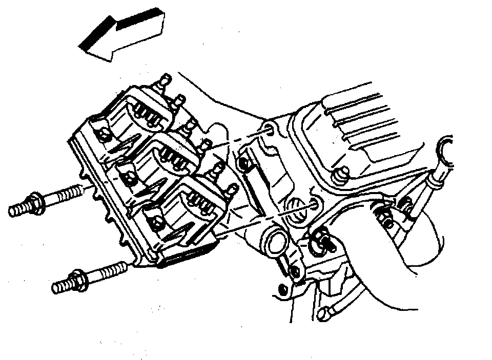
11. Install the generator support bracket to the cylinder head. Install the generator. Refer to Generator Replacement in Starting and Charging.
Picture 7
12. Install the electronic ignition module.
13. Connect the spark plug wires.
14. Install the drive belt tensioner. Refer to Drive Belt Tensioner Replacement (VIN 1) and to Drive Belt Tensioner Replacement (VIN 1 - Supercharger).
15. Install the power steering pump. Refer to Power Steering Pump Replacement in Steering.
16. Install the fuel pipe heat shield.
17. Connect the negative battery cable.
__________________________________
Let me know what you find or if you have other questions.
Take care,
Joe
Images (Click to enlarge)
Feb 3, 2019 at 7:53 PM