Hi and thanks for using 2CarPros.com.
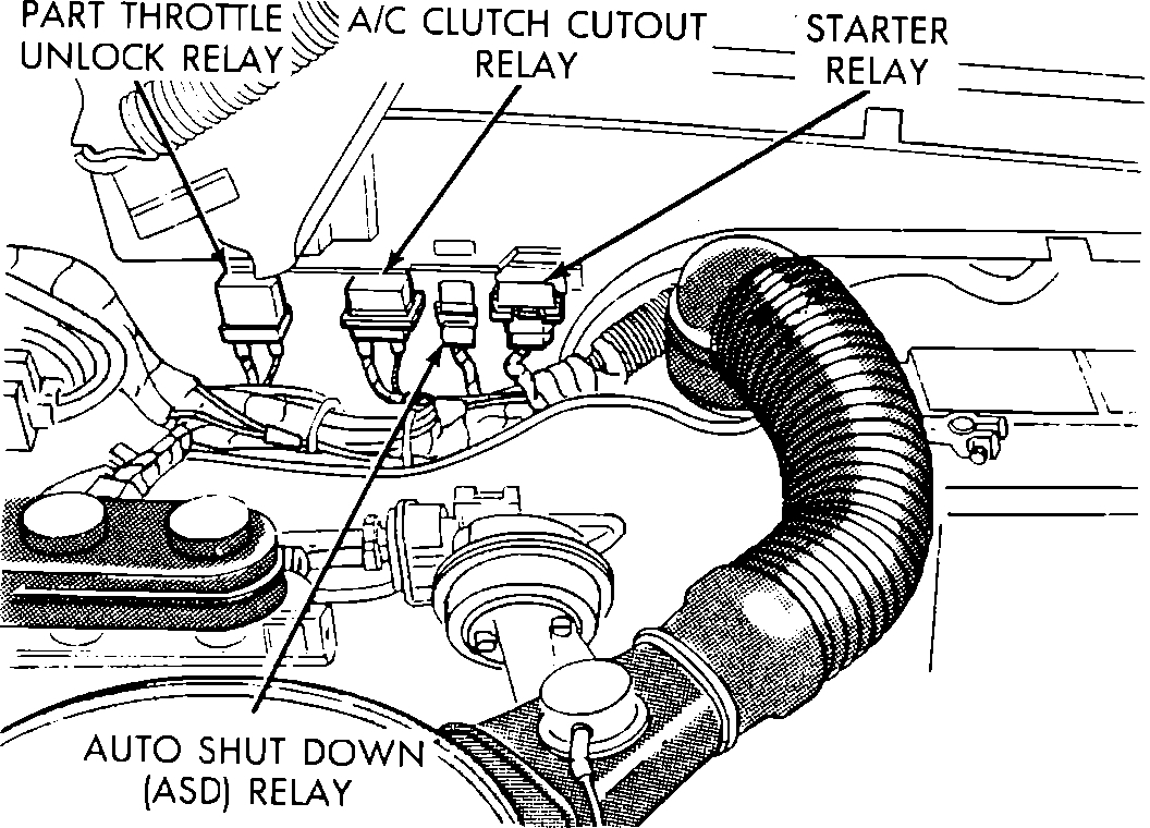
The first thing I would check is the auto shut down relay (ASD). The Auto Shutdown relay is located in the engine compartment on the left hand fender. See picture 1.
_____________________________________
Here are the directions for checking it. All remaining pictures correlate with these directions.
AUTO SHUTDOWN (ASD) RELAY
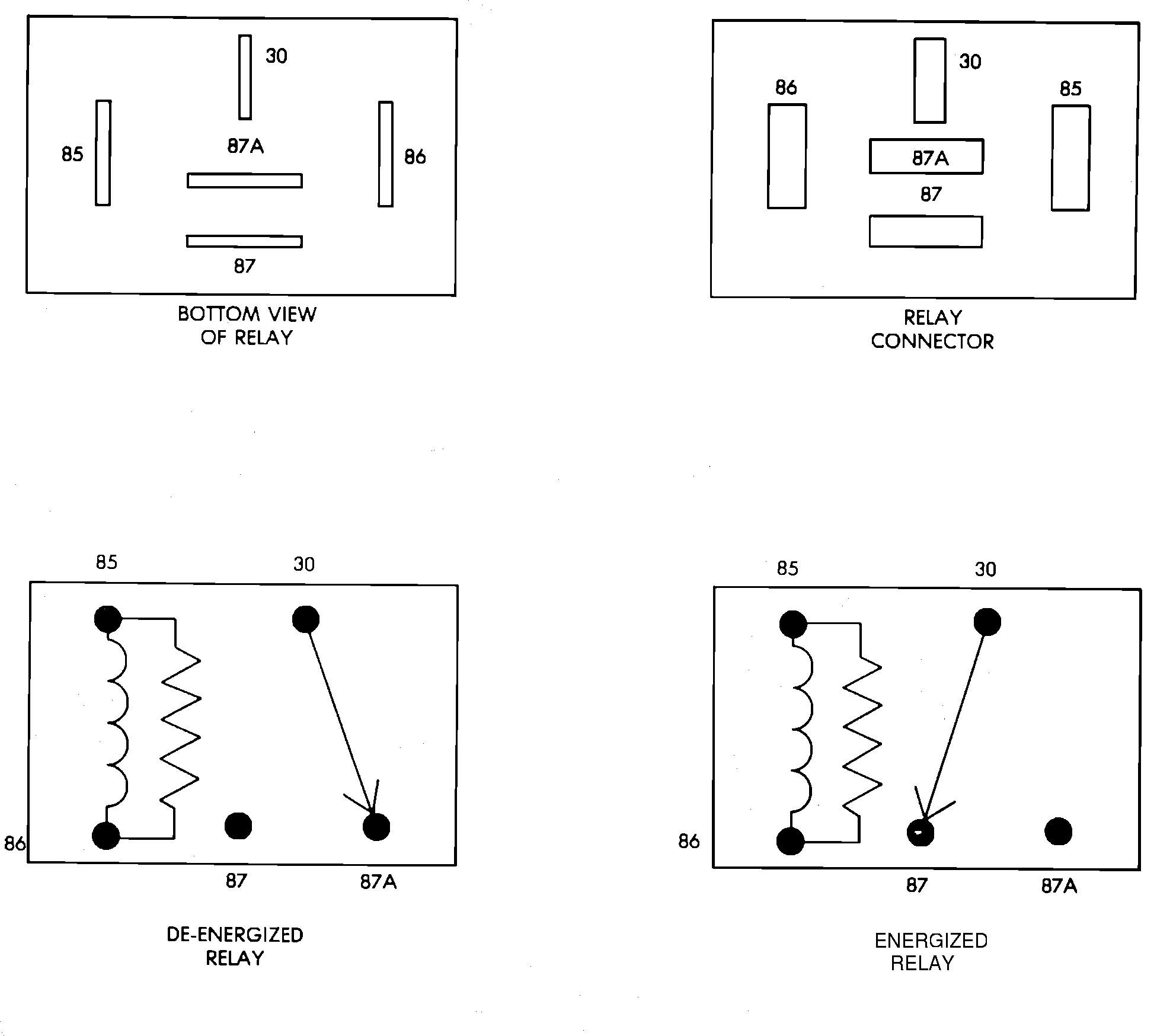
Relay Terminal Identification
ASD RELAY TERMINAL IDENTIFICATION
The following is a list of the terminal numbers, with circuit codes, and color codes, and their function:
Circuit No.Terminal No.Color Code Description
J11 30 Red Has battery input voltage supplied through fusible link.
Z1 87 DG/BK Connected to J11 circuit (terminal 30) in the energized position, supplies output voltage to fuel pump, O2 sensor, fuel injectors, and coil.
K14 86 DB/WT Connected to the electromagnet, (diode) and the Single Module Engine Controller (SMEC). The SMEC provides input voltage to relay.
DK19 85 DB/YL Connected to the electromagnet (diode) and grounded by the SMEC when distributor signal is present.
N/A 87A N/A Not used in these applications.
ASD RELAY TEST
NOTE: The ASD relay operation may be tested with the use of the DRB II scanner or equivalent.
If no scanner is available proceed with the following test.
1. Connect a voltmeter to the J11 (terminal 30) wire at the ASD connector. Check for battery voltage. If no voltage is present, check fusible links and supply voltage from the battery. If voltage is present proceed to step 2.
2. Connect the voltmeter to the Z1 (terminal 87) wire at the ASD connector. Turn the ignition key to the START position and CRANK the engine. If output voltage is present during cranking, the ASD relay is functioning normally and no further testing of the ASD relay is necessary. If no voltage is present at the Z1 wire, proceed to step 3.
3. Connect the voltmeter to the K14 (terminal 86) wire at the ASD connector. Turn the ignition key to the RUN position. Input voltage from the SMEC to the ASD relay should be present. If voltage is present proceed to step 4. If no voltage is present, disconnect the 60 way and 14 way SMEC connectors, and the ASD relay connector. Connect an ohmmeter between the K14 (terminal 86) wire and the DB/WT wire at pin no. 12 of the SMEC, and check for continuity. If continuity exists, the problem is computer related.
If no continuity exists, repair open in wire, reconnect SMEC and ASD relay, and test operation.
4. Connect voltmeter to DK19 (terminal 85) wire at ASD connector. Turn ignition key to START position, and CRANK engine, while observing voltage at DK19. Voltage should be present at DK19 and drop to less than 1 volt within 2 seconds during cranking. If voltage drops ASD relay is functioning, and no further testing of the ASD relay is necessary. If voltage does not drop, proceed to step 5. If no voltage is present, disconnect the ASD relay, and connect an ohmmeter between the K14 (terminal 86) and DK19 (terminal 85) of the ASD relay and check for continuity. If no continuity exists replace and ASD relay and test operation.
5. Disconnect the 60 way SMEC connector and ASD relay. Connect an ohmmeter between the DK19 wire at the ASD relay connector and the DB/YL wire at pin connector no. 58 of the SMEC. Check for continuity. If no continuity exists repair open in wire, reconnect SMEC and ASD relay, and test operation. If continuity exists, the problem is computer related.
Images (Click to enlarge)
Sep 19, 2018 at 6:07 PM