Wiring diagram for the instrument panel needed?

Tiny
GVINCNET52
  • MEMBER
  • 2000 CHEVROLET SILVERADO
  • 4.3L
  • V6
  • 4WD
  • MANUAL
  • 296,000 MILES
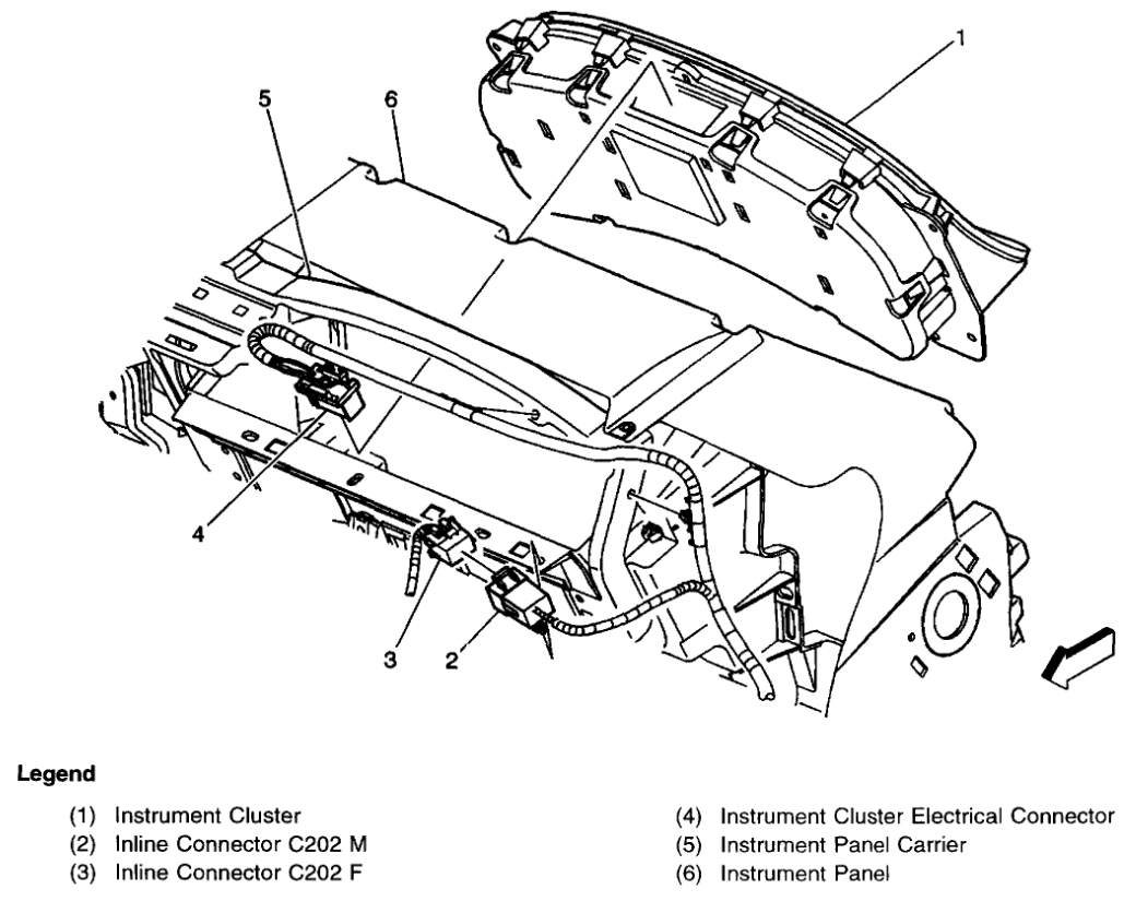
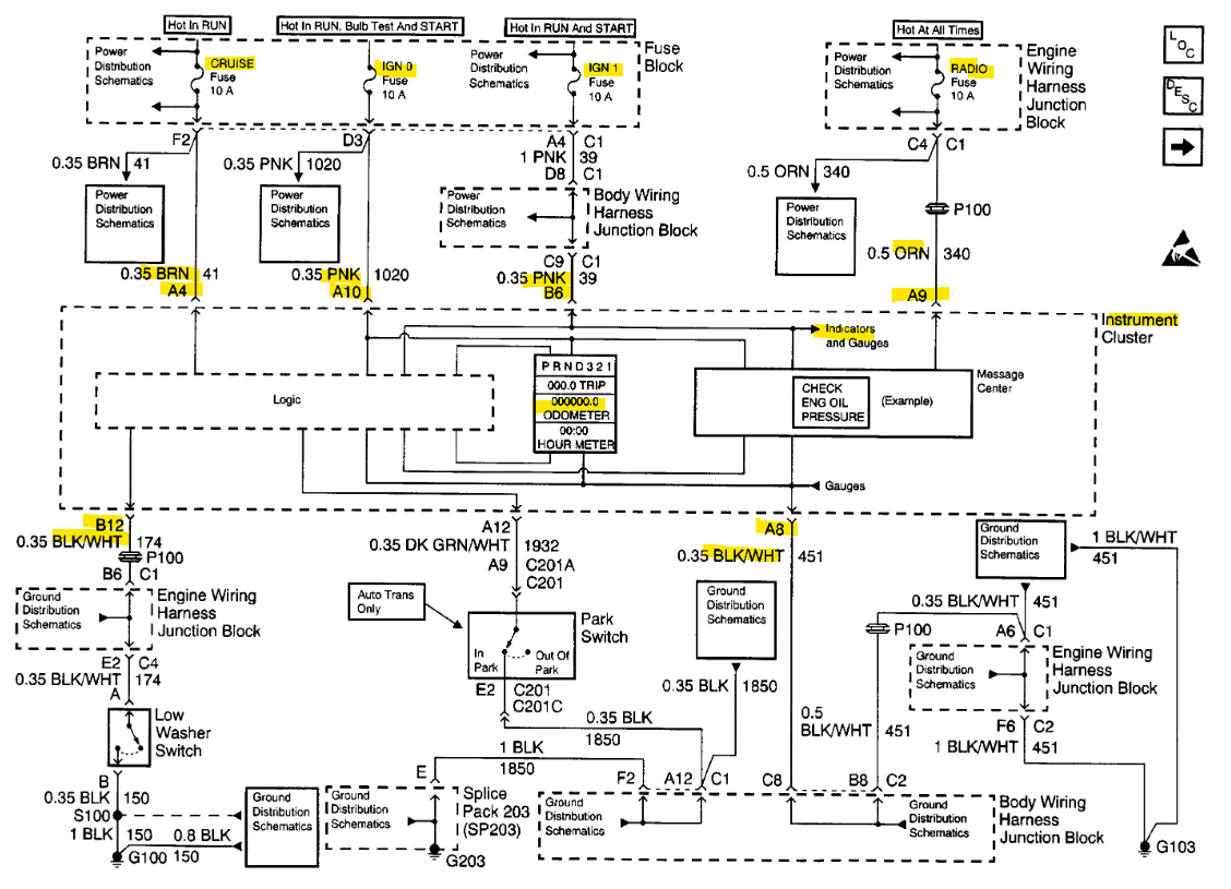
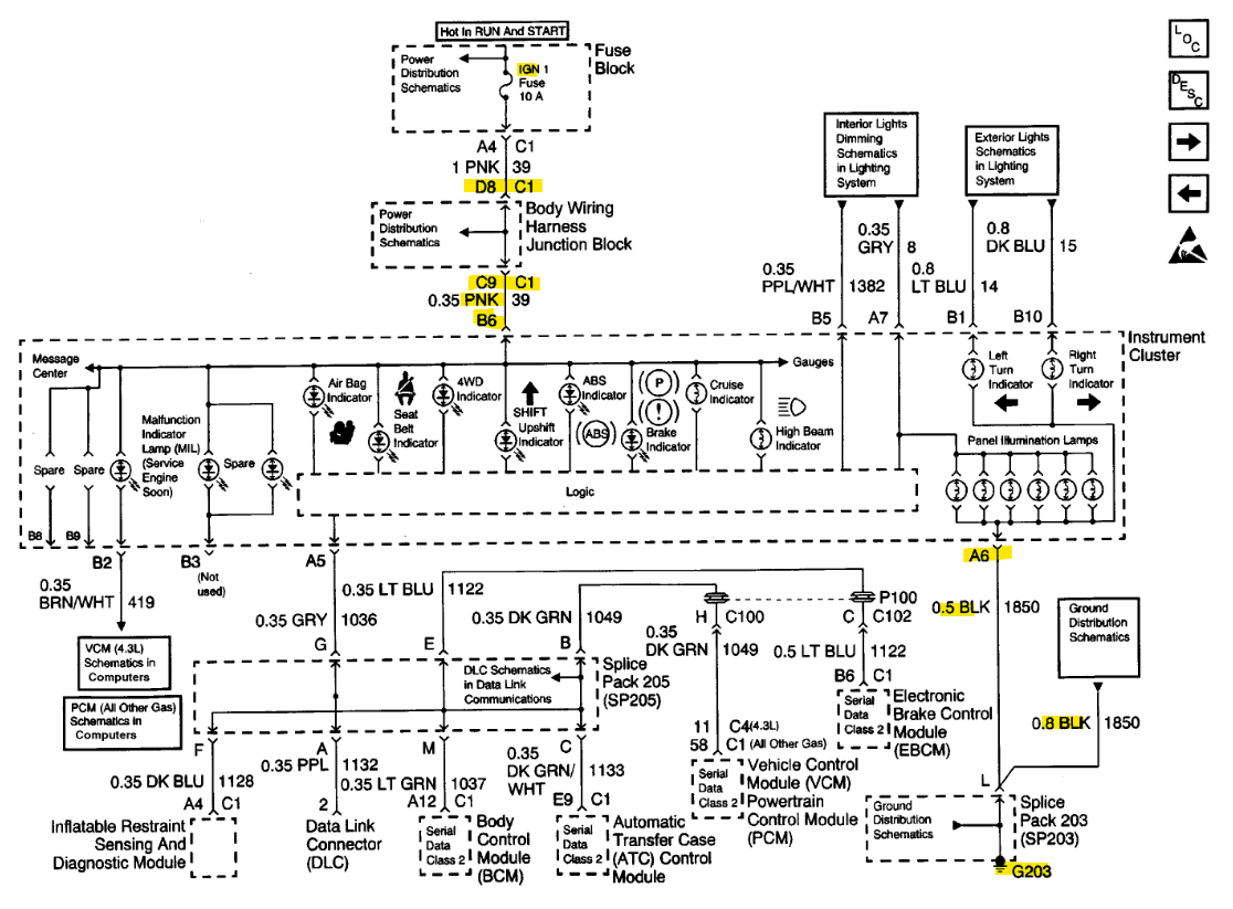
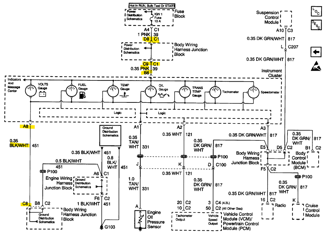
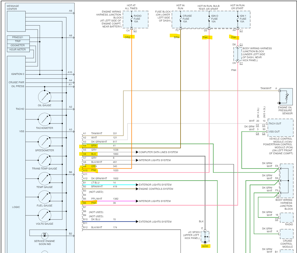
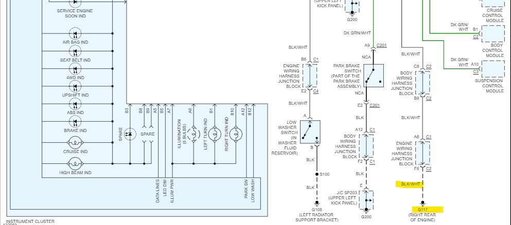
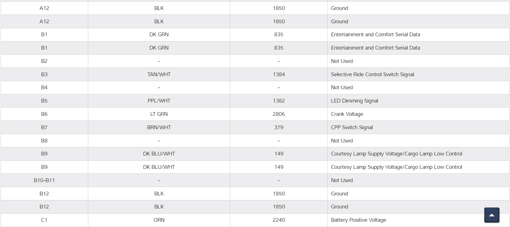
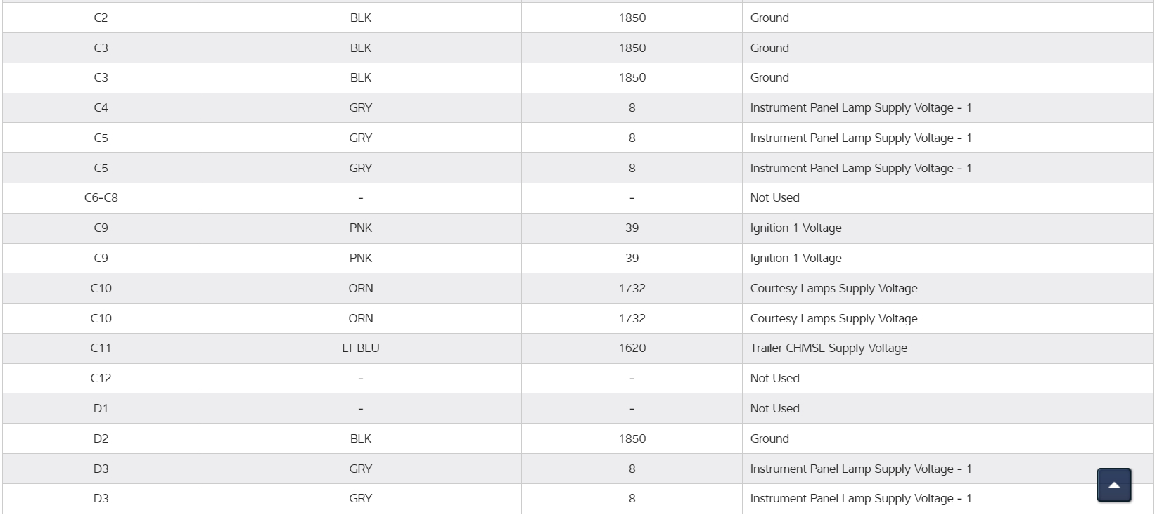
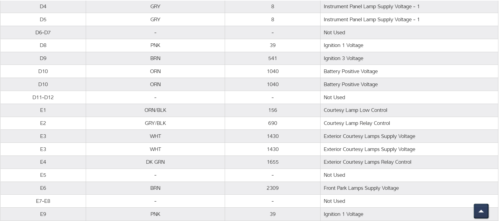
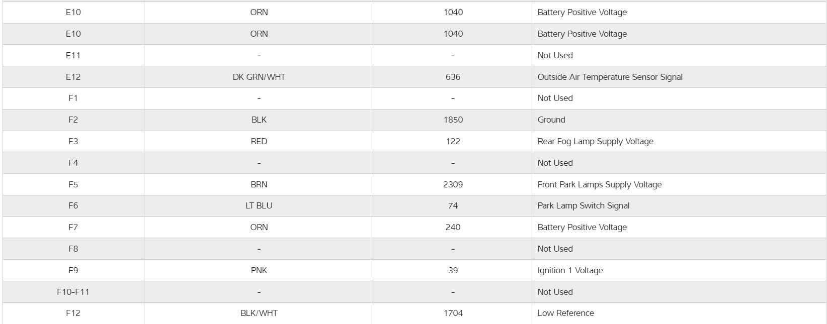
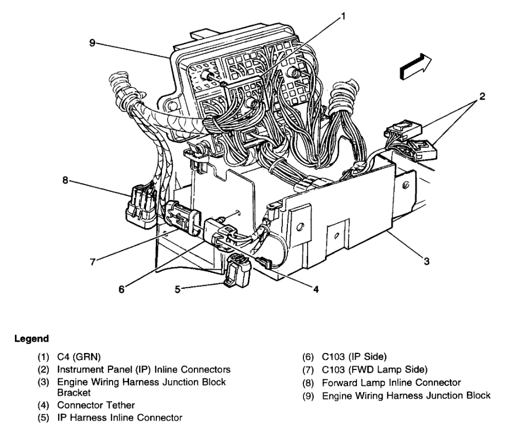
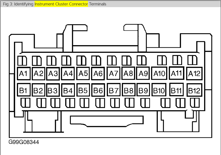
Instrument panel gauges and odometer are intermittent. On and off when hitting a bump. Checked for cold solder joints on the panel. After reconnecting the cluster and turning power on to test I noticed that as I moved it around it would go on and off. I suspect broken wire/s in the harness. I need the harness diagram for my vehicle VIN W to troubleshoot. Any help would be greatly appreciated.
Monday, July 24th, 2023 AT 8:36 AM

5 Replies

Tiny
AL514
  • MECHANIC
  • 4,122 POSTS
Hello, there looks to be about 4 power feeds, Im not sure how many grounds yet, but do you still have the Cluster out where you could back probe the connector and see which feed or ground you could be losing while doing the wiggle test, that way you can have a wire color to concentrate on, instead of just having to go through every wire. You could use a test light or multimeter, a test light would be easier to see when a feed drops out on you. Ill get the diagrams for the Cluster for you, they are in 3 groups but not difficult to understand.
Diagrams 1-4 are the oem Chevy Cluster, 5, 6 are the aftermarket diagrams, 8-12 are for the harness connector C1 which you can see quite a few pins in the oem diagrams.
Im looking for a better connector diagram for the Cluster pinout.
The 14th diagram is the Cluster connector pinout.
Was this
answer
helpful?
Yes
No
Monday, July 24th, 2023 AT 2:31 PM
Tiny
GVINCNET52
  • MEMBER
  • 5 POSTS
I appreciate the troubleshooting tips and the diagrams etc. I am an electronics technician with 53 years' experience so the schematics and pinout diagrams will be most helpful as they seem to be the most accurate, I have found so far. Through further testing I have come to the conclusion that there are multiple issues with the cluster and or wiring. The truck has 296,000 miles on it, so I am not surprised. I will continue until the issues are resolved and will provide an update and any new information that may be helpful to others once I am successful. Thank you for your assistance.
Was this
answer
helpful?
Yes
No
Wednesday, July 26th, 2023 AT 8:56 AM
Tiny
AL514
  • MECHANIC
  • 4,122 POSTS
I seem to be getting a lot of these Chevrolet 4.3 and 5.3 around this year 2000 to 2004 with Cluster issues lately. It's the summer heat that brings out the problems. That cluster is sitting in the upper dash which is baking in the sun all day. It causes pin fitment issues in connectors and solder joint issues on the boards. But this is definitely a year where more Chevrolets are having these issues. I know that 2nd to last diagram is not the greatest, but there will be another connector in series from the Cluster connector, so if you can follow the Cluster wiring, it should lead you to that other connector there. But having a test light in place I've found is the best way, because you'll see it flash or flicker when you get to that section of the harness which has an open in it. And wires open up inside of harnesses, they don't always need to be exposed to elements or anything. It can be a factory defect that's just now showing up. But you have more years of experience in electronics than I do. Next, I'll be emailing you about some issue. I do a lot of electronics builds on the side.
Was this
answer
helpful?
Yes
No
Wednesday, July 26th, 2023 AT 10:59 AM
Tiny
GVINCNET52
  • MEMBER
  • 5 POSTS
I apologize for this being a rather lengthy update. This turned out to be a rather common but often overlooked issue. I proceeded by once again removing the cluster to check for broken wires. I probed the two power and two ground wires which all proved to be intact with solid connections. While I had the cluster out, I put it back on the bench and verified there were no bad connections or solder joints. I also verified as well as I could that electronic components were working as they should and had not deteriorated over time and use. To my surprise when I reinstalled the cluster everything functioned correctly. This was unexpected but completely understandable. This brings us to that common but often overlooked issue. For those of you with limited experience, connector sets are made up of male and female connectors. The male side has pins which fit into the female sockets. The pins are solid while the contacts in the socket are allowed to move some. Over time and with repeated disconnects and reconnects, the socket contacts can open or spread causing, you got it intermittent contact. Evidently while probing the connector, I tightened the contacts on the female connector and solidified the connection, alas everything is back to normal for now. I hope this helps some of you that may have this very issue. I also want to caution you that the correct way to fix this issue is to disassemble the connector and very gently tighten the socket contacts. This is something that takes years of experience and practice. If you don't have the experience your best option is to replace the connector. Once again I hope this clarifies some things and helps others.
Was this
answer
helpful?
Yes
No
Wednesday, August 2nd, 2023 AT 11:38 AM
Tiny
AL514
  • MECHANIC
  • 4,122 POSTS
Yeah, I have seen many pin fitment issues, it happens a lot. Unfortunately, I get a lot of people who just pull modules, mostly PCMs and change them out. But you're correct, it takes many years to learn these things. It would be nice if they would ask for help before replacing modules and tearing everything apart, get those almost every day. I'm at about the 20-year mark, my issue is keeping up with technology now. Things advance so much each year. I think I spend more time researching and learning new tech than actually working on it. But anyway. Glad you found the issue. Have a good evening.
Was this
answer
helpful?
Yes
No
Wednesday, August 2nd, 2023 AT 11:51 AM

Please login or register to post a reply.

Sponsored links