Where is the input speed sensor located

Tiny
FRESHLIKE78
  • MEMBER
  • 2002 PONTIAC GRAND PRIX
  • 3.8L
  • 2WD
  • AUTOMATIC
  • 206,852 MILES
Speedometer still not going the right speed and car is like it does not want to shift because it don't know the right speed it's going.
Friday, April 10th, 2020 AT 7:59 AM

17 Replies

Tiny
ASEMASTER6371
  • MECHANIC
  • 52,797 POSTS
Good morning,

Do you have any codes set in the system?

If the speedometer is not working, that is the vehicle speed sensor, not the input speed sensor. This will also effect the shifting points as well.

https://www.2carpros.com/articles/automatic-transmission-problems

Roy

1. Raise and support the vehicle. Refer to Vehicle Lifting.
2. Remove the right front tire and wheel.
3. Remove the vehicle speed sensor VSS electrical connector.

imageOpen In New TabZoom/Print

4. Remove the VSS bolt (9).
5. Remove the VSS (10) from the extension case.

imageOpen In New TabZoom/Print

6. Remove the O-ring (11) from the VSS (10).
Was this
answer
helpful?
Yes
No
-1
Friday, April 10th, 2020 AT 8:27 AM
Tiny
FRESHLIKE78
  • MEMBER
  • 14 POSTS
Hi there, I do not have a code and I have changed the speed sensor and it still doing the same thing. Maybe I got a bad one.
Was this
answer
helpful?
Yes
No
+2
Friday, April 10th, 2020 AT 8:30 AM
Tiny
ASEMASTER6371
  • MECHANIC
  • 52,797 POSTS
Do you have a scan tool to monitor live data? See if you have a speed signal from the transmission to the ECM.

Roy
Was this
answer
helpful?
Yes
No
Friday, April 10th, 2020 AT 8:34 AM
Tiny
FRESHLIKE78
  • MEMBER
  • 14 POSTS
No, I do not. But just for I can know where would the input speed sensor be located? They say to change both when you do it and maybe I bought a bad output speed sensor.
Was this
answer
helpful?
Yes
No
Friday, April 10th, 2020 AT 8:41 AM
Tiny
ASEMASTER6371
  • MECHANIC
  • 52,797 POSTS
Okay, I attached the location and the procedure for the input speed sensor.

Again, it has no effect on the speedometer working at all.

That is controlled by the vehicle speed sensor.

Can you get a scan tool to do the readings?

Roy

1. Remove the case side cover.
2. Disconnect the input speed sensor electrical connector.
3. Remove the input speed sensor clip (441) from the case cover.
4. Remove the input speed sensor (440) from the case cover.

ImageOpen In New TabZoom/Print

5. Inspect the input speed sensor (440) for the following conditions:
Damaged or missing magnet
Damaged housing
Bent or missing electrical terminals
Damaged speed sensor clip (441)
Was this
answer
helpful?
Yes
No
Friday, April 10th, 2020 AT 8:48 AM
Tiny
FRESHLIKE78
  • MEMBER
  • 14 POSTS
Okay, where is it located is it under the car? And no I do not have a scan tool.
Was this
answer
helpful?
Yes
No
Friday, April 10th, 2020 AT 8:56 AM
Tiny
ASEMASTER6371
  • MECHANIC
  • 52,797 POSTS
You have to take the side cover off the side of the transmission as in the instructions. It is on the valve body.

I posted the procedure below.

Roy

Case Side Cover Replacement
Removal Procedure
1. Disconnect the negative battery cable.
2. Remove the air cleaner intake duct.
3. Remove the engine mount struts.
4. Install the engine support fixture.
5. Disconnect the transmission wiring harness connector.
6. Raise and support the vehicle. Refer to Vehicle Lifting.
7. Remove the left drive axle from the transaxle.
8. Secure the drive axle to the steering knuckle/strut.

Caution: Failure to disconnect the intermediate shaft from the rack and pinion stub shaft can result in damage to the steering gear and/or damage to the intermediate shaft. This damage may cause loss of steering control which could result in personal injury.

9. Remove the intermediate steering shaft pinch bolt and the shaft from the steering gear.
10. Remove the 3-way catalytic converter pipe from right exhaust manifold.
11. Support the right and the left side of the frame with jackstands.
12. Remove the transaxle mount.
13. Loosen the engine mount lower nuts.
14. Loosen the right side frame bolts and remove the left side frame bolts.
15. Adjust the jackstand to the lower left side of the frame.
16. Position the drain pan under the transaxle.

ImageOpen In New TabZoom/Print

17. Remove the case side cover bolts (5-58).

ImageOpen In New TabZoom/Print

18. Remove the case side cover pan (53).
19. Remove the case side cover gasket (54).
20. Clean the case.
21. Clean the side cover gasket mating surfaces.
Was this
answer
helpful?
Yes
No
+1
Friday, April 10th, 2020 AT 9:37 AM
Tiny
FRESHLIKE78
  • MEMBER
  • 14 POSTS
Okay, thank you so much. I will try and get a scan tool to see what is going on. Thank you
Was this
answer
helpful?
Yes
No
Friday, April 10th, 2020 AT 9:45 AM
Tiny
ASEMASTER6371
  • MECHANIC
  • 52,797 POSTS
You are welcome.

Keep us updated.

Always glad to help.

Roy
Was this
answer
helpful?
Yes
No
+1
Friday, April 10th, 2020 AT 9:51 AM
Tiny
FRESHLIKE78
  • MEMBER
  • 14 POSTS
I will.
Was this
answer
helpful?
Yes
No
Friday, April 10th, 2020 AT 9:54 AM
Tiny
ASEMASTER6371
  • MECHANIC
  • 52,797 POSTS
We are always glad to help.

Roy
Was this
answer
helpful?
Yes
No
Friday, April 10th, 2020 AT 9:57 AM
Tiny
FRESHLIKE78
  • MEMBER
  • 14 POSTS
Hi there. I finally have the code it is P0502 it is the speed sensor that I changed. I think I bought I defected one from Amazon.
Was this
answer
helpful?
Yes
No
Monday, May 4th, 2020 AT 2:56 PM
Tiny
ASEMASTER6371
  • MECHANIC
  • 52,797 POSTS
Okay, this code is for the vehicle speed sensor which is different from the input speed sensor.

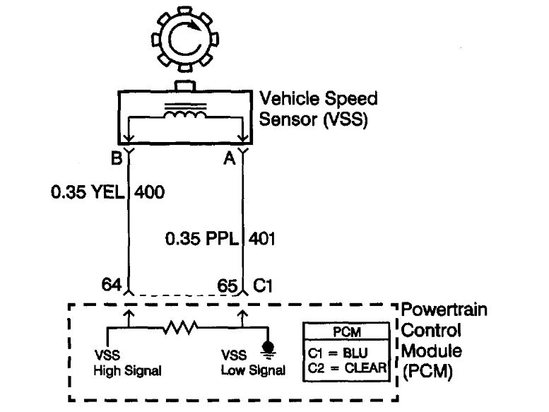
I attached a flow chart with a wiring diagram. Does the speedometer work?

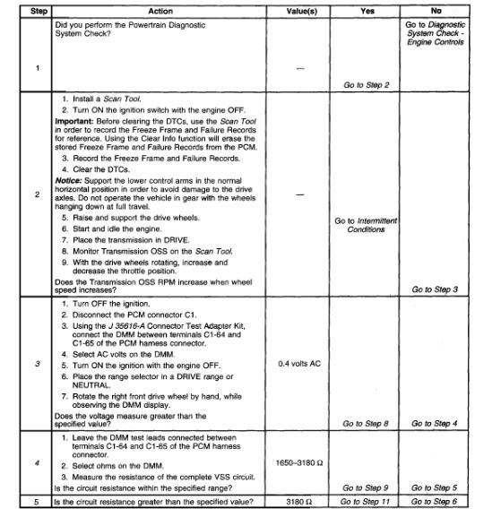
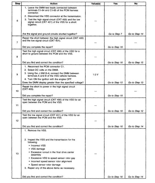
I posted below the description and a flow chart for you to follow.

Roy

Circuit Description
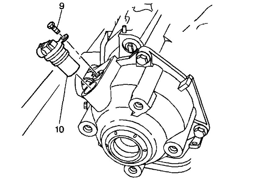
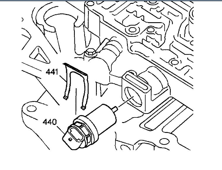
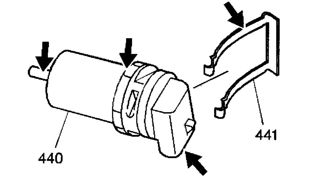
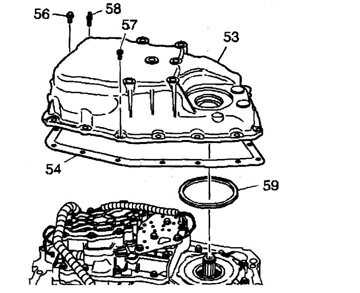
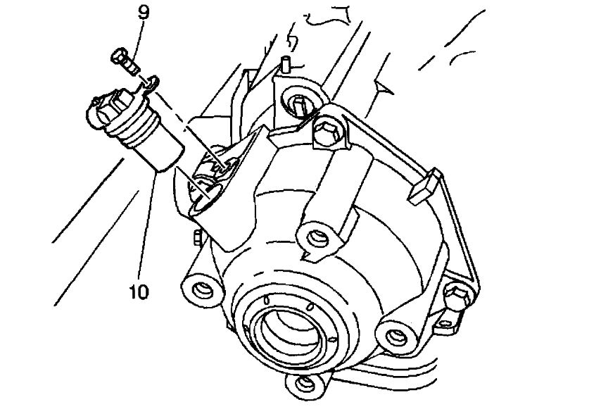
The Vehicle Speed Sensor (VSS) system is a pulse generator consisting of a speed sensor assembly, located in the case extension, and a toothed vehicle speed sensor reluctor wheel, which is pressed onto the final drive carrier assembly. As the vehicle drives forward, the vehicle speed sensor reluctor wheel rotates. This rotation produces a variable AC signal in the pickup coil that is proportional to vehicle speed. The PCM uses this signal in order to calculate vehicle speed, shift timing and gear ratios.
If the PCM detects a low vehicle speed with a high engine speed while in a drive range, then DTC P0502 sets. DTC P0502 is a type B DTC.

Conditions for Running the DTC
No MAP sensor DTC P0107 or P0108.
No TP sensor DTC P0121, P0122 or P0123.
No AT ISS DTC P0716 or P0717.
No TFP manual valve position switch DTC P1810.
The TP angle is 12% or greater.
The engine torque is 55 - 400 Nm (40 - 300 ft. Lbs.).
The transmission is not in PARK or NEUTRAL.
The input shaft speed is 1,500 RPM or greater.

Conditions for Setting the DTC
The output shaft speed is less than 150 RPM for 2.5 seconds.

Action Taken When the DTC Sets
The PCM illuminates the Malfunction Indicator Lamp (MIL) during the second consecutive trip in which the Conditions for Setting the DTC are met.
The PCM commands maximum line pressure.
The PCM freezes shift adapts.
The PCM calculates vehicle speed from the AT input shaft speed sensor for shift timing.
The PCM records the operating conditions when the Conditions for Setting the DTC are met. The PCM stores this information as Freeze Frame and Failure Records.
The PCM stores DTC P0502 in PCM history during the second consecutive trip in which the Conditions for Setting the DTC are met.

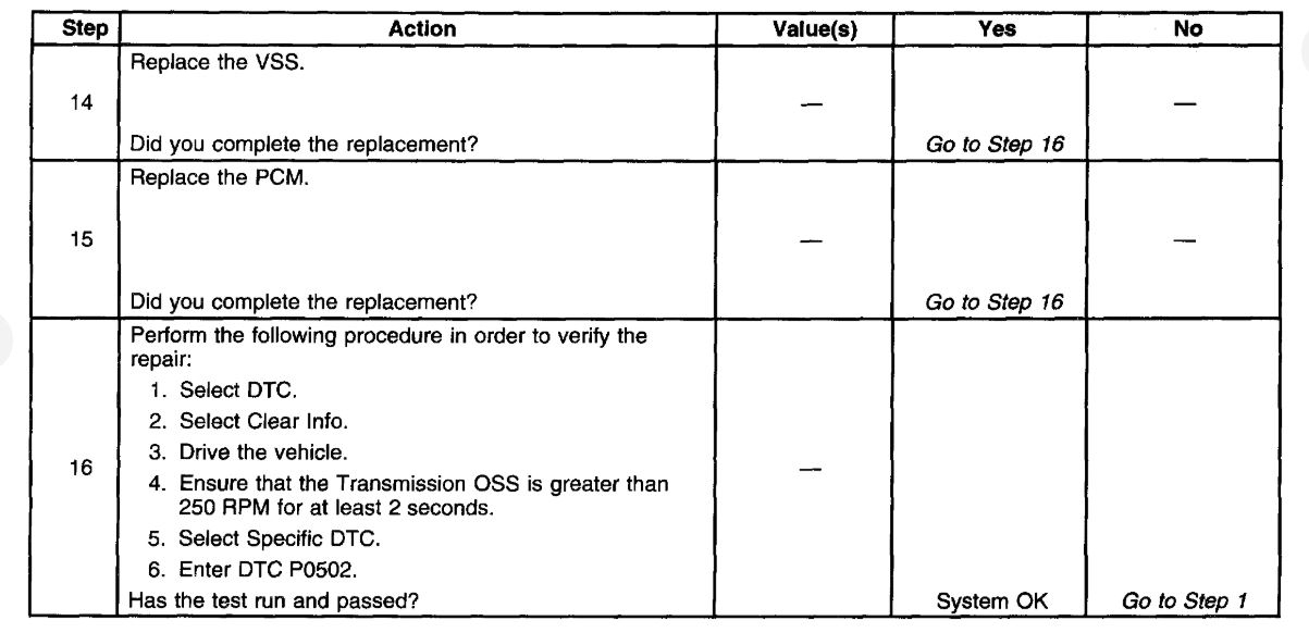
Conditions for Clearing the MIL/DTC
The PCM turns OFF the MIL during the third consecutive trip in which the diagnostic test runs and passes.
A scan tool can clear the MIL/DTC.
The PCM clears the DTC from PCM history if the vehicle completes 40 warm-up cycles without an emission-related diagnostic fault occurring.
The PCM cancels the DTC default actions when the ignition switch is OFF long enough in order to power down the PCM.
Was this
answer
helpful?
Yes
No
Monday, May 4th, 2020 AT 3:16 PM
Tiny
FRESHLIKE78
  • MEMBER
  • 14 POSTS
The speedometer does work but it goes up and then back down and then it might stop and then it will go back up and down then the car will jerk.
Was this
answer
helpful?
Yes
No
Monday, May 4th, 2020 AT 6:03 PM
Tiny
ASEMASTER6371
  • MECHANIC
  • 52,797 POSTS
Okay that is why the code is setting.

You have an erratic reading and that will set the code. I would replace the sensor and make sure the connector pins are clean, tight and not damaged.

Roy
Was this
answer
helpful?
Yes
No
+1
Monday, May 4th, 2020 AT 6:07 PM
Tiny
FRESHLIKE78
  • MEMBER
  • 14 POSTS
Okay, thank you. I will try that I will let you know how it goes. Thanks
Was this
answer
helpful?
Yes
No
Monday, May 4th, 2020 AT 6:15 PM
Tiny
ASEMASTER6371
  • MECHANIC
  • 52,797 POSTS
You are welcome.

Always glad to help.

Roy
Was this
answer
helpful?
Yes
No
+1
Monday, May 4th, 2020 AT 6:19 PM

Please login or register to post a reply.

Sponsored links