Procedure below.
Roy
REMOVAL
WARNING: To avoid personal injury or death, on vehicles equipped with airbags, disable the supplemental restraint system before attempting any steering wheel, steering column, airbag, occupant classification system, seat belt tensioner, impact sensor, or instrument panel component diagnosis or service. Disconnect and isolate the battery negative (ground) cable, then wait two minutes for the system capacitor to discharge before performing further diagnosis or service. This is the only sure way to disable the supplemental restraint system. Failure to take the proper precautions could result in accidental airbag deployment.
WARNING: To avoid personal injury or death, never strike or drop the occupant restraint controller, as it can damage the impact sensor or affect its calibration. The occupant restraint controller contains the impact sensor, which enables the system to deploy the supplemental restraints. If an airbag control module is accidentally dropped during service, the module must be scrapped and replaced with a new unit. Failure to observe this warning could result in accidental, incomplete, or improper supplemental restraint deployment.
CAUTION: On vehicles equipped with the Occupant Classification System (OCS), never replace both the Occupant Restraint Controller (ORC) and the Occupant Classification Module (OCM) at the same time. If both require replacement, replace one. Then perform the supplemental restraint verification test before replacing the other. Both the ORC and the OCM store OCS calibration data, which they transfer to one another when one of them is replaced. If both are replaced at the same time, an irreversible fault will be set in both modules.
ImageOpen In New TabZoom/Print
1. Before proceeding with the following repair procedure, review all warnings and cautions. See: Dashboard / Instrument Panel > Vehicle Damage Warnings > Restraint System
2. Disconnect and isolate battery negative cable.
3. Using a trim stick C-4755 or equivalent, remove the left door sill trim cover.
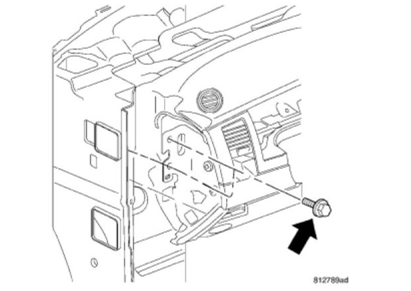
4. Remove the screw and remove the left cowl trim cover.
5. Remove the left instrument panel end cap.
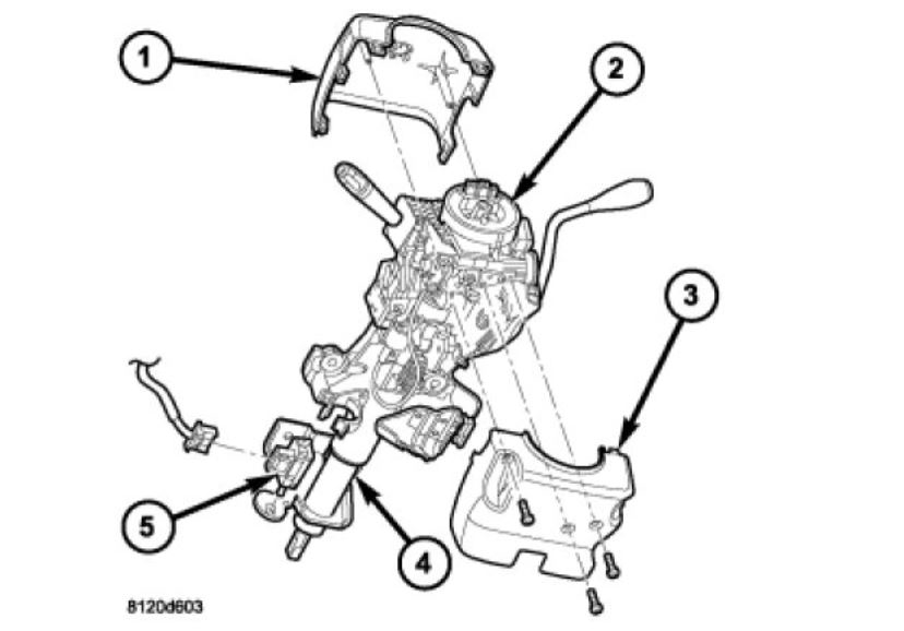
6. Remove the two screws (1) and remove the steering column opening cover (2).
ImageOpen In New TabZoom/Print
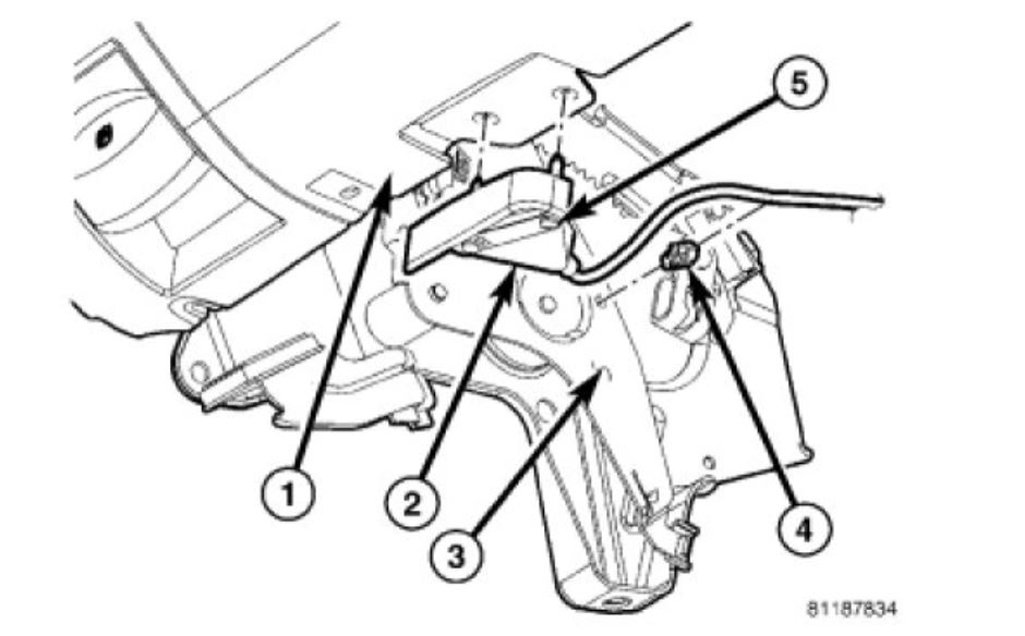
7. Remove the screws (5) and position aside the hood release handle (2).
ImageOpen In New TabZoom/Print
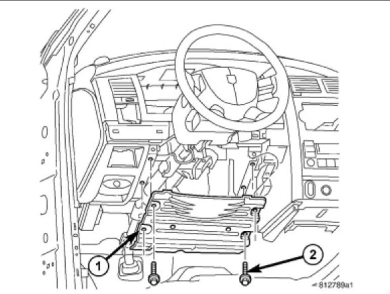
8. Remove the four screws (2) and remove the steering column opening reinforcement (1).
ImageOpen In New TabZoom/Print
9. Remove the steering column tilt lever.
10. Remove the upper (1) and lower (3) column shrouds.
ImageOpen In New TabZoom/Print
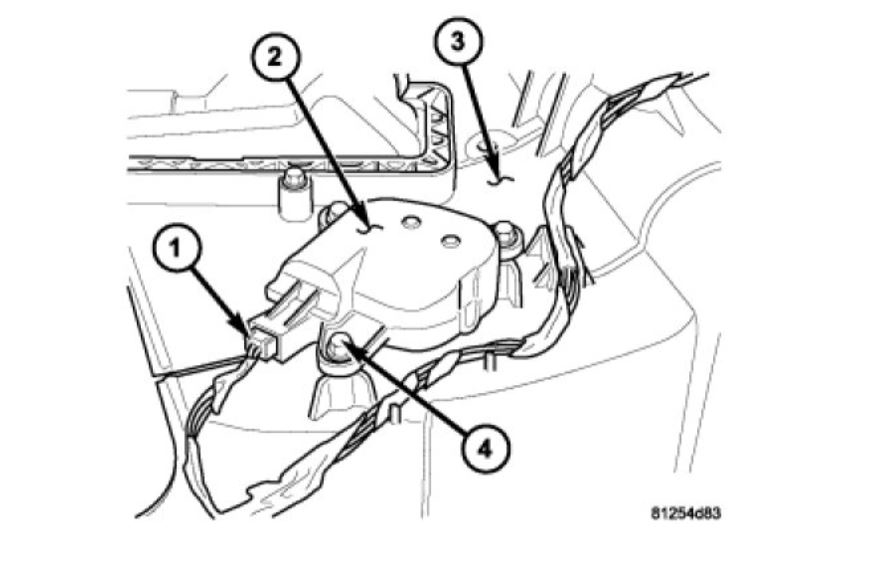
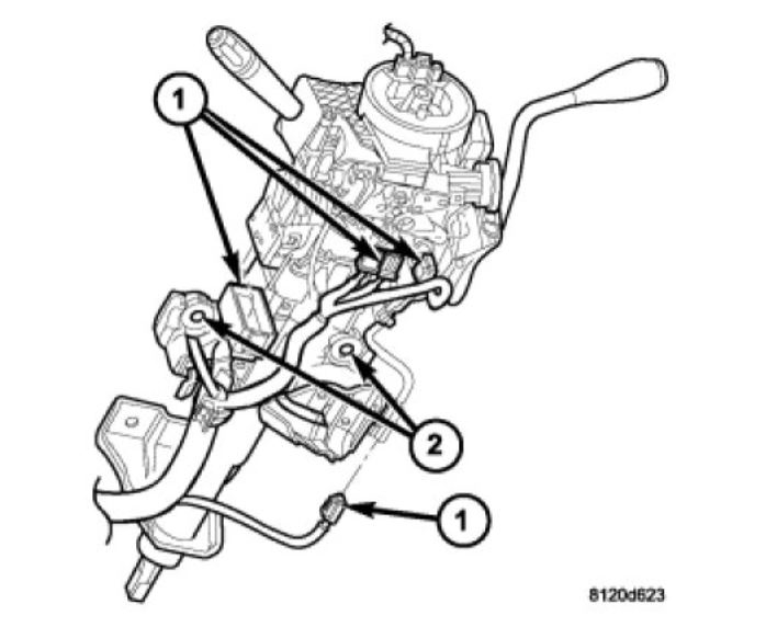
11. Disconnect the wiring harness connectors (1) to the column.
12. Remove the shift cable from the column shift lever actuator.
13. Release the shift cable from the column bracket and remove it from the bracket.
14. Remove the SKIM module in order to disconnect the electrical connector.
ImageOpen In New TabZoom/Print
15. Remove the upper steering shaft coupler bolt (2) and slide the shaft (3) down.
ImageOpen In New TabZoom/Print
16. Remove the brake light switch (5) and discard See: Brake Light Switch > Removal and Replacement > Removal.
ImageOpen In New TabZoom/Print
17. Remove the four steering column mounting nuts (3).
18. Lower the column from the mounting studs (1).
19. Remove the steering column assembly (2) from the vehicle.
ImageOpen In New TabZoom/Print
20. Remove the pedal support bracket bolts.
ImageOpen In New TabZoom/Print
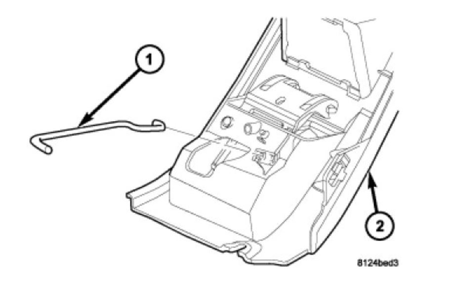
21. Disengage the release rod (1) from the arm on the pedal assembly.
ImageOpen In New TabZoom/Print
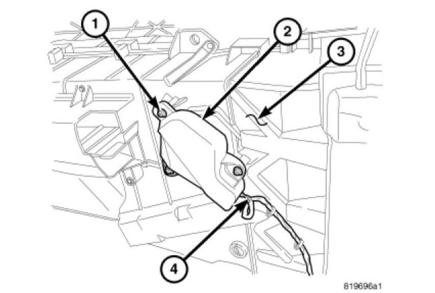
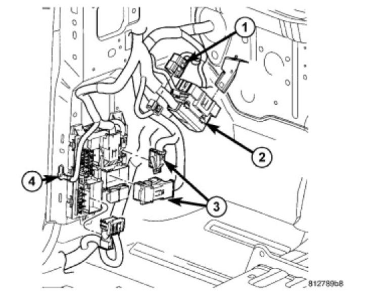
22. Disconnect the electrical connectors (1, 2 and 3) from the fuse block.
23. Remove the bolt and remove the ground wire (4).
24. Open the trim covers in the driver's side A-pillar grab handle and remove the bolts.
25. Remove the A-pillar trim panel.
26. Remove the floor console. See: Console > Removal and Replacement > Floor Console - Removal
imageOpen In New TabZoom/Print
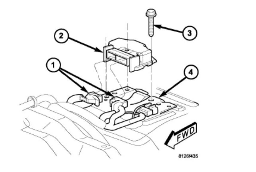
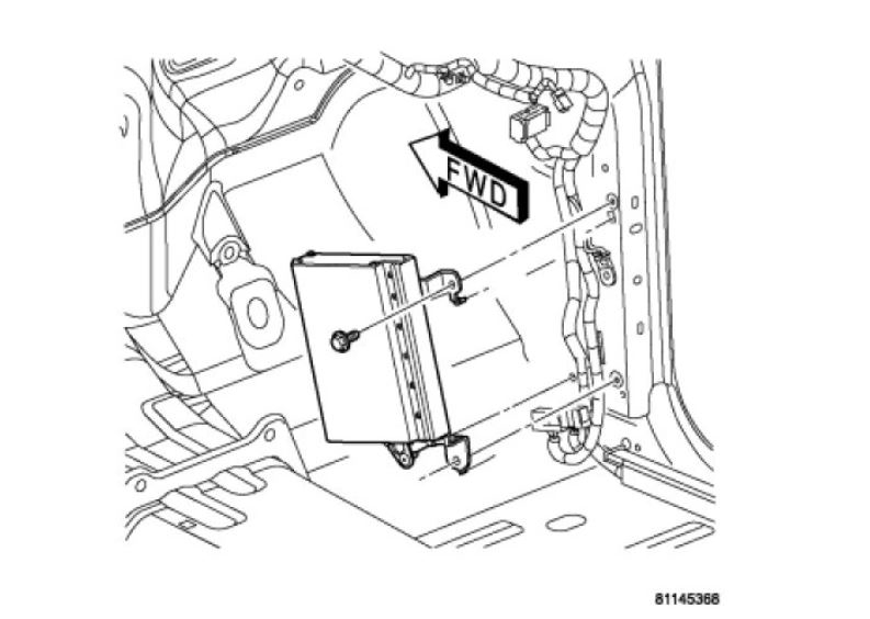
27. Disconnect the two body wire harness connectors (1) from the Occupant Restraint Controller (ORC) (2) connector receptacles located on the forward facing side of the module. To disconnect the wire harness connectors from the ORC, depress the release tab and lift the lever arm on each connector.
ImageOpen In New TabZoom/Print
28. Position the carpet aside and remove the center harness screws (1). Pull instrument panel wiring harness (2) from under the carpet.
ImageOpen In New TabZoom/Print
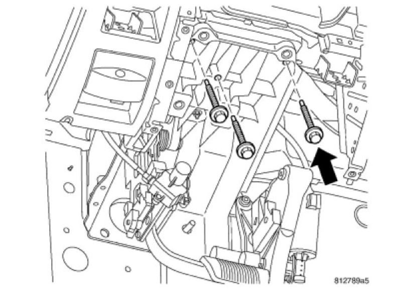
29. Remove the center support bolts.
30. Remove the driver's seat. See: Seats > Removal and Replacement > Seat - Removal
31. Remove the driver's side floor duct.
ImageOpen In New TabZoom/Print
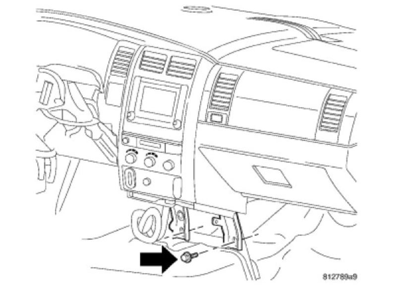
32. Remove the driver's side support bolts.
ImageOpen In New TabZoom/Print
33. Remove the right instrument panel end cap.
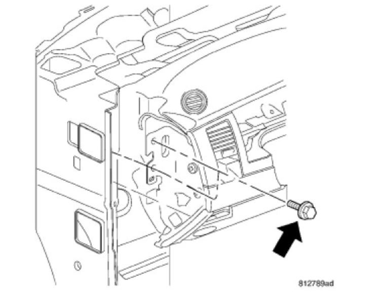
34. Remove the passenger side support bolts.
NOTE: driver's side shown, passenger side similar.
ImageOpen In New TabZoom/Print
35. Using a trim stick C-4755 or equivalent, remove the right door sill trim cover.
36. Remove the screw and remove the right cowl trim cover.
37. Remove the bolts and remove the amplifier.
38. Disconnect the amplifier and antenna electrical connectors.
ImageOpen In New TabZoom/Print
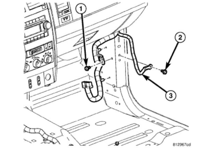
39. Remove the harness bolt (1) and the ground wire(3) bolt (2).
40. Remove the passenger side rear floor duct.
ImageOpen In New TabZoom/Print
41. Open the trim covers in the passenger side A-pillar grab handle and remove the bolts.
42. Remove the A-pillar trim panel.
43. Using a trim stick C-4755 or equivalent, remove the instrument panel defroster grille.
44. Disconnect the sensor electrical connector (3), if equipped.
ImageOpen In New TabZoom/Print
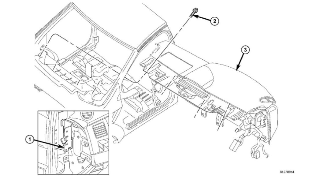
45. Remove the four fenceline bolts (2).
46. Lift the instrument panel assembly (3) off the side support pins (1) and remove assembly through the driver's door.
Images (Click to make bigger)
Monday, October 22nd, 2018 AT 10:46 AM