Hi and thanks for using 2CarPros, com.
Most often, if special tooling is not used when installing the timing chain, the cam timing is jeopardized. This can cause noise. I am going to provide you an extensive list of directions. I need you to read through them and confirm you did what is listed. All attached pictures correlate with these directions.
_______________________________
CAMSHAFTS
Camshafts
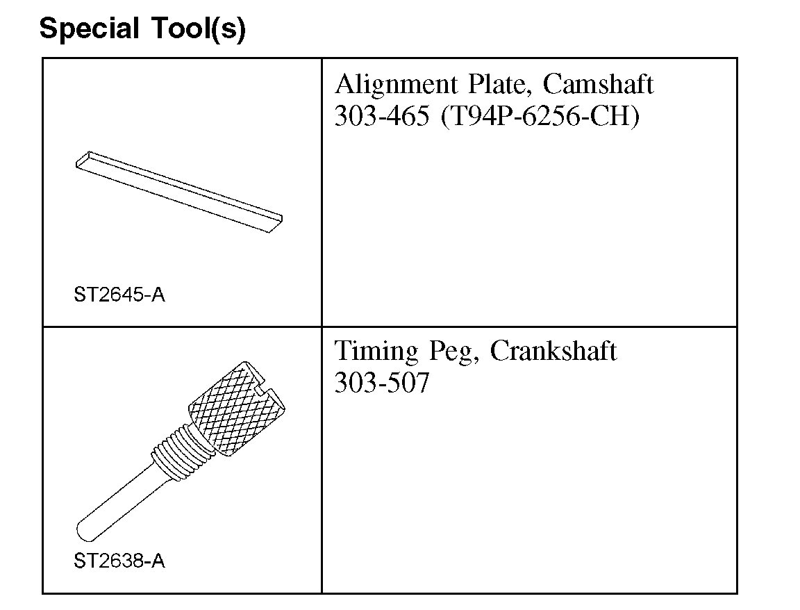
Special Tool(s)
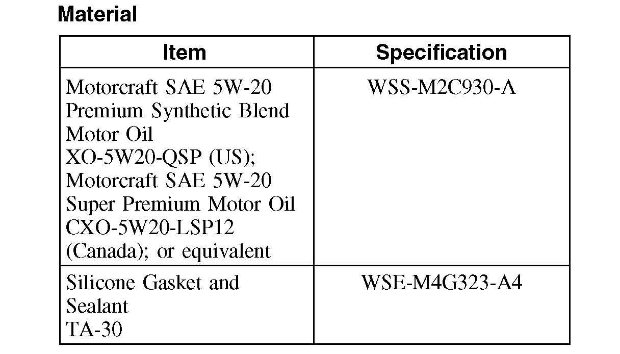
Material
Removal
CAUTION: During engine repair procedures, cleanliness is extremely important. Any foreign material (including any material created while cleaning gasket surfaces) that enters the oil passages, coolant passages or the oil pan can cause engine failure.
CAUTION: Do not rotate the camshafts unless instructed to in this procedure. Rotating the camshafts or crankshaft with timing components loosened or removed can cause serious damage to the valves and pistons.
1. With the vehicle in NEUTRAL, position it on a hoist. For additional information, refer to Maintenance/Service and Repair.
2. Remove the coolant expansion tank. For additional information, refer to Cooling System.
3. Remove the RF wheel and tire.
4. Check the valve clearance. For additional information, refer to Valve Clearance Check. See: Engine > Procedures > Valve Clearance Check
5. Remove the accessory drivebelt. For additional information, refer to Drive Belts, Mounts, Brackets and Accessories.
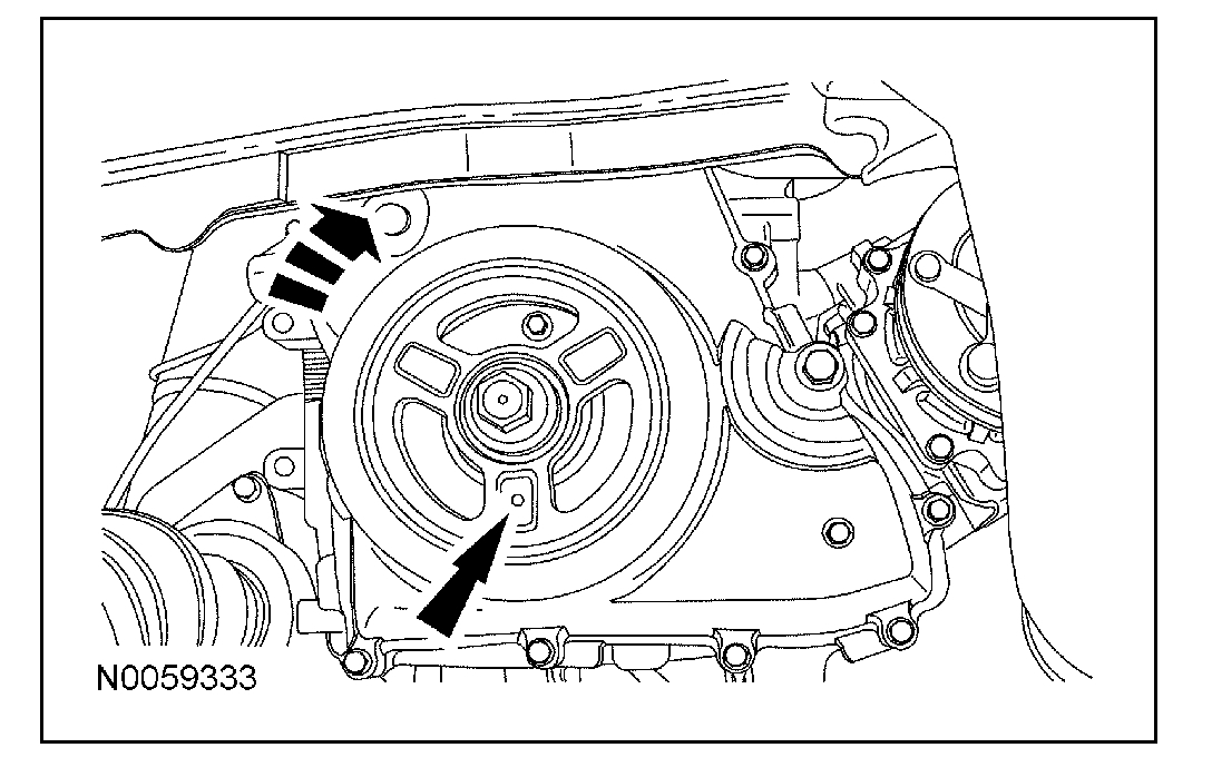
6. CAUTION: Failure to position the No. 1 piston at top dead center (TDC) can result in damage to the engine. Turn the engine in the normal direction of rotation only.
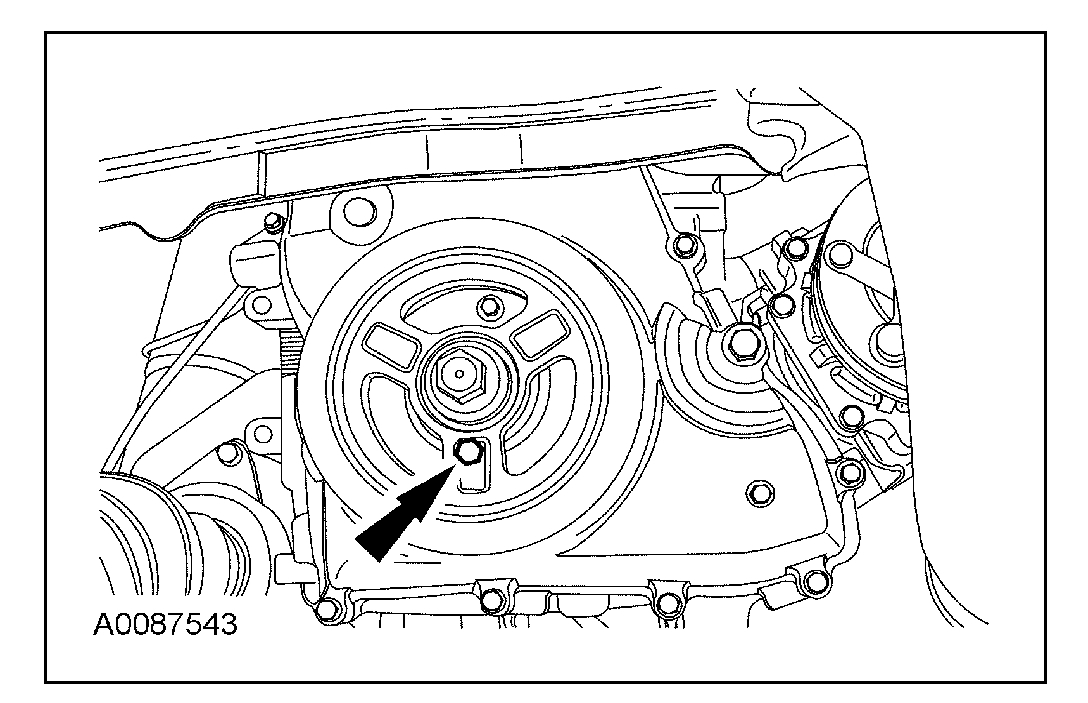
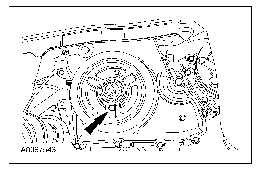
Using the crankshaft pulley bolt, turn the crankshaft clockwise to position the No. 1 piston at top dead center (TDC).
The hole in the crankshaft pulley should be in the 6 o'clock position.
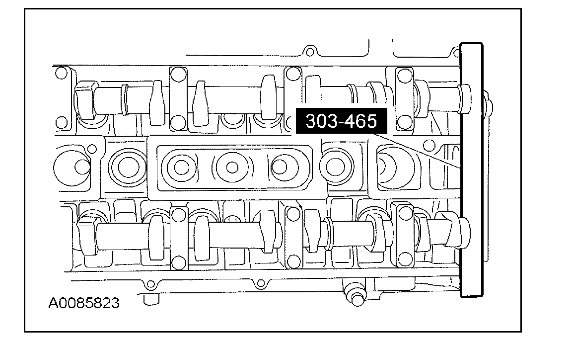
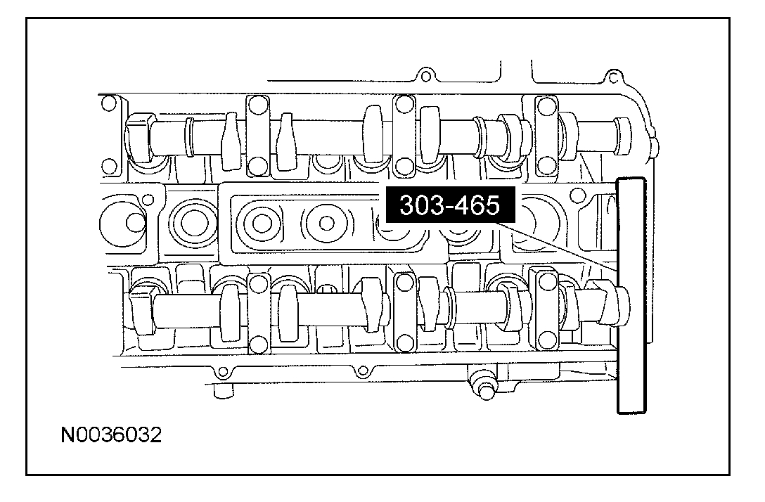
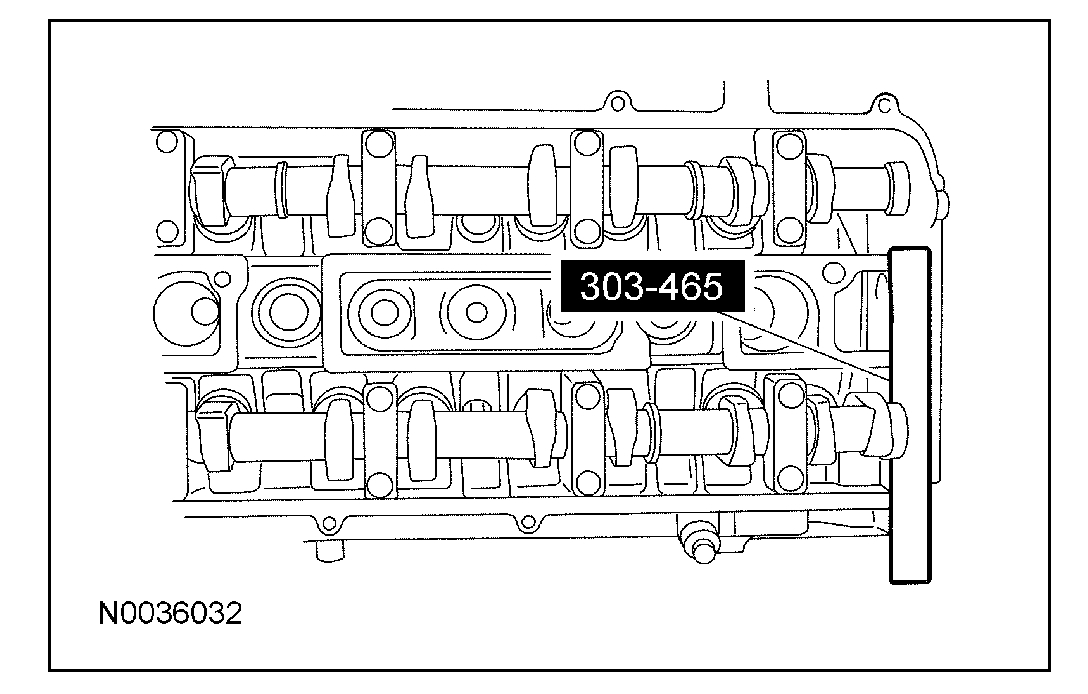
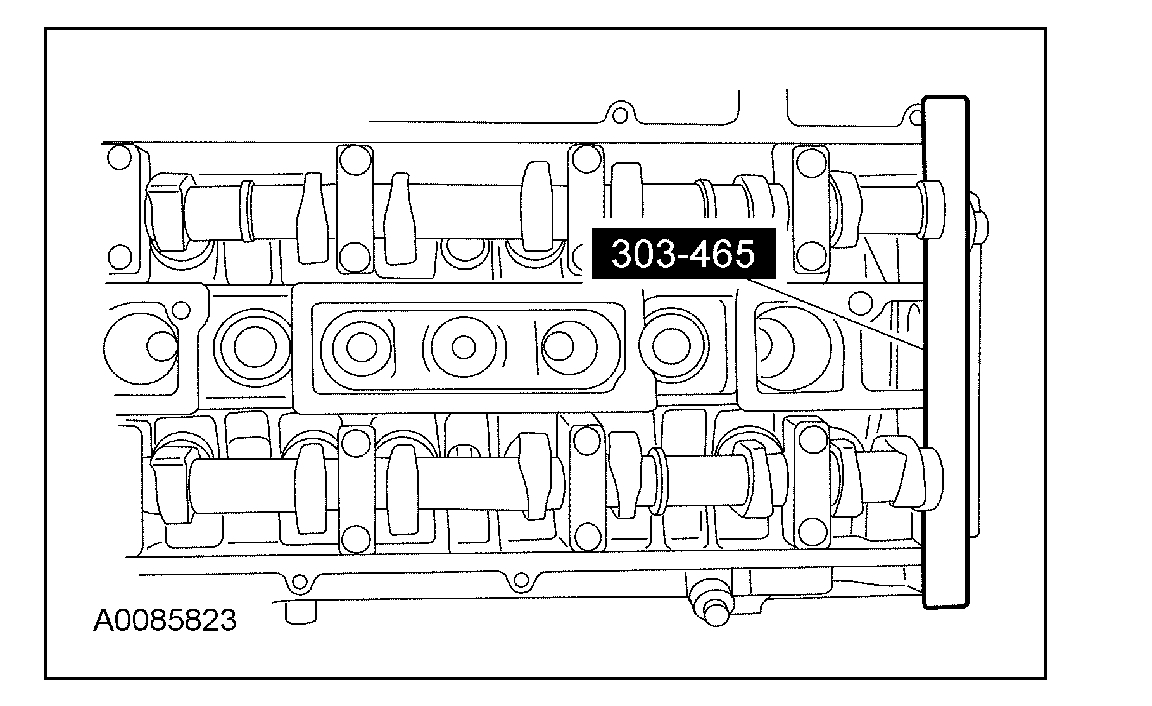
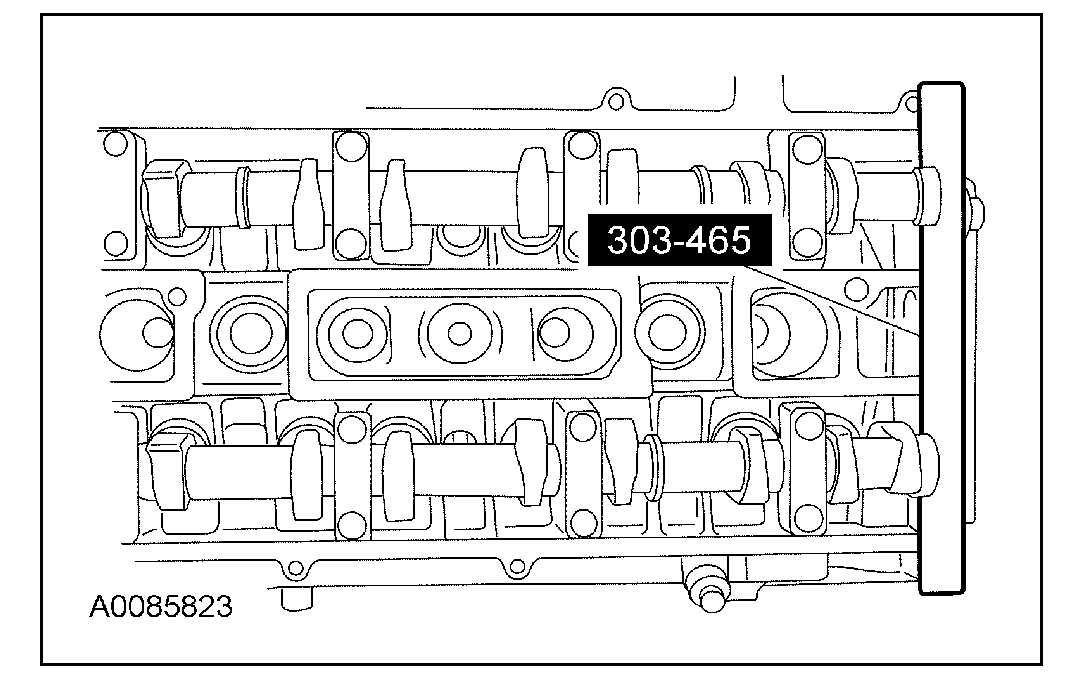
7. CAUTION: The special tool (303-465) is for camshaft alignment only. Using this tool to prevent engine rotation can result in engine damage.
NOTE: The camshaft timing slots are offset. If the special tool cannot be installed, rotate the crankshaft one complete revolution clockwise to correctly position the camshafts.
Install the special tool in the slots on the rear of both camshafts.
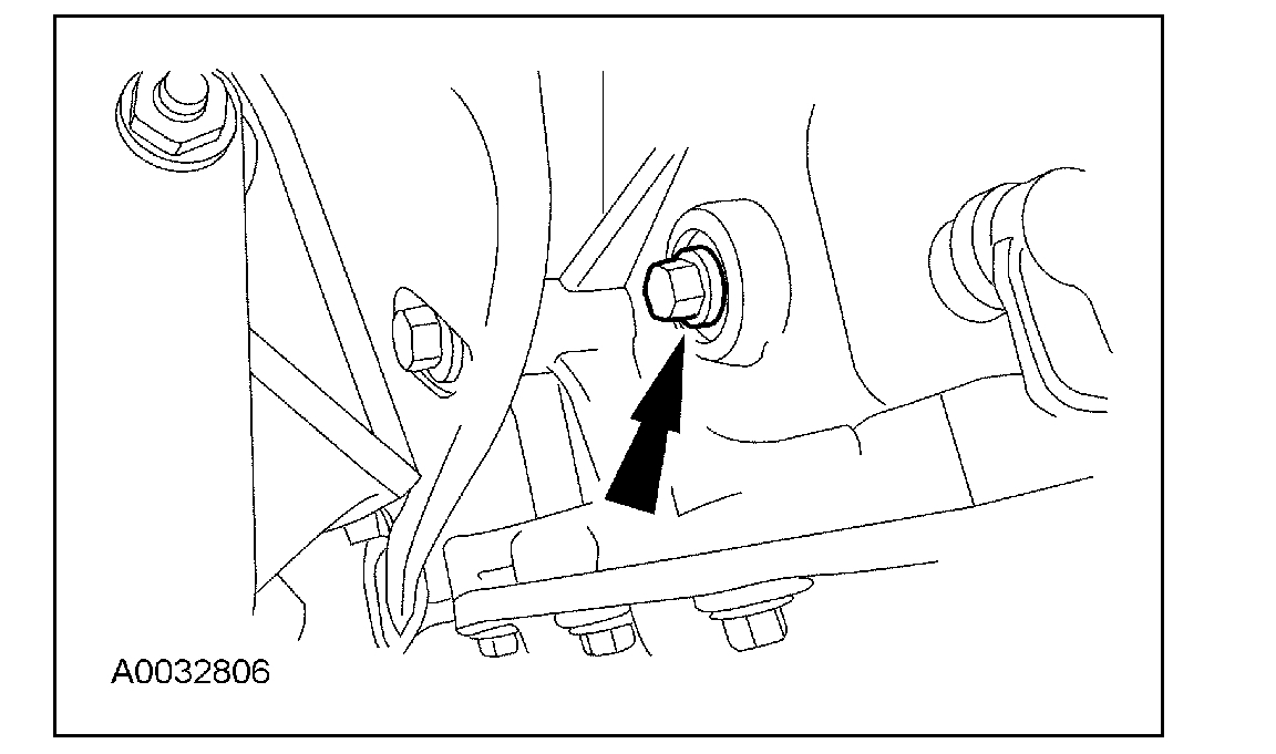
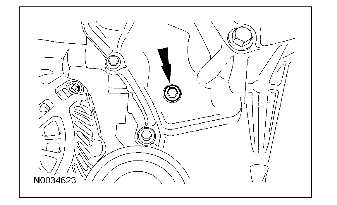
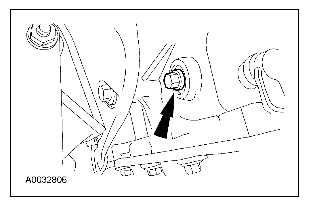
8. Remove the engine plug bolt.
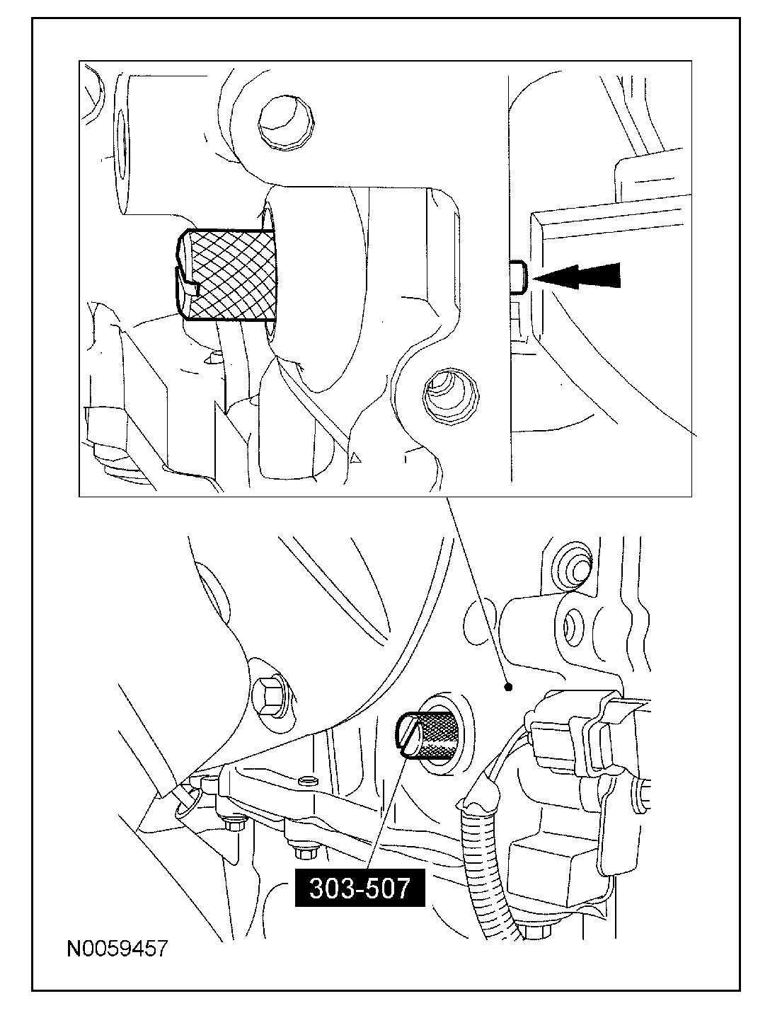
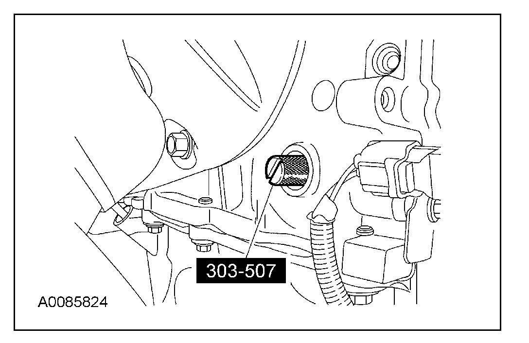
9. NOTE: The special tool will contact the crankshaft and prevent it from turning past TDC. However, the crankshaft can still be rotated in the counterclockwise direction. The crankshaft must remain at the TDC position during the camshaft removal and installation.
Install the special tool.
10. CAUTION: Only hand-tighten the bolt or damage to the front cover can occur.
Install a standard 6 mm (0.23 in) x 18 mm (0.7 in) bolt through the crankshaft pulley and thread it into the front cover.
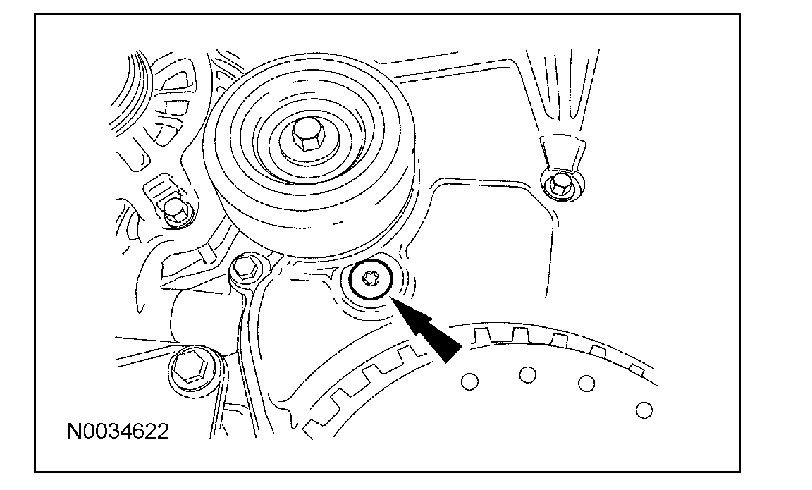
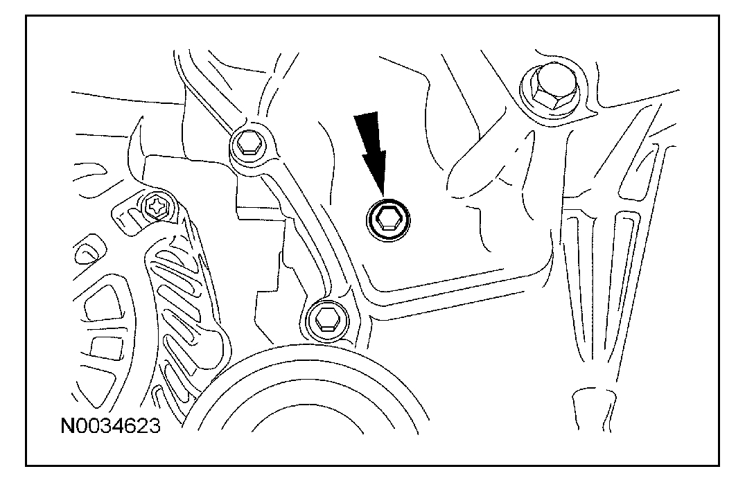
11. Remove the front cover lower timing hole plug from the engine front cover.
12. Remove the front cover upper timing hole plug from the engine front cover.
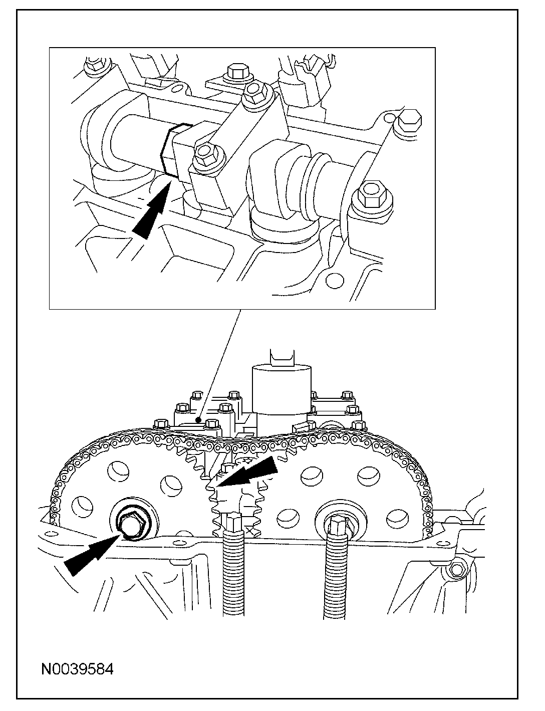
13. Reposition the special tool to the slot on the rear of the intake camshaft only.
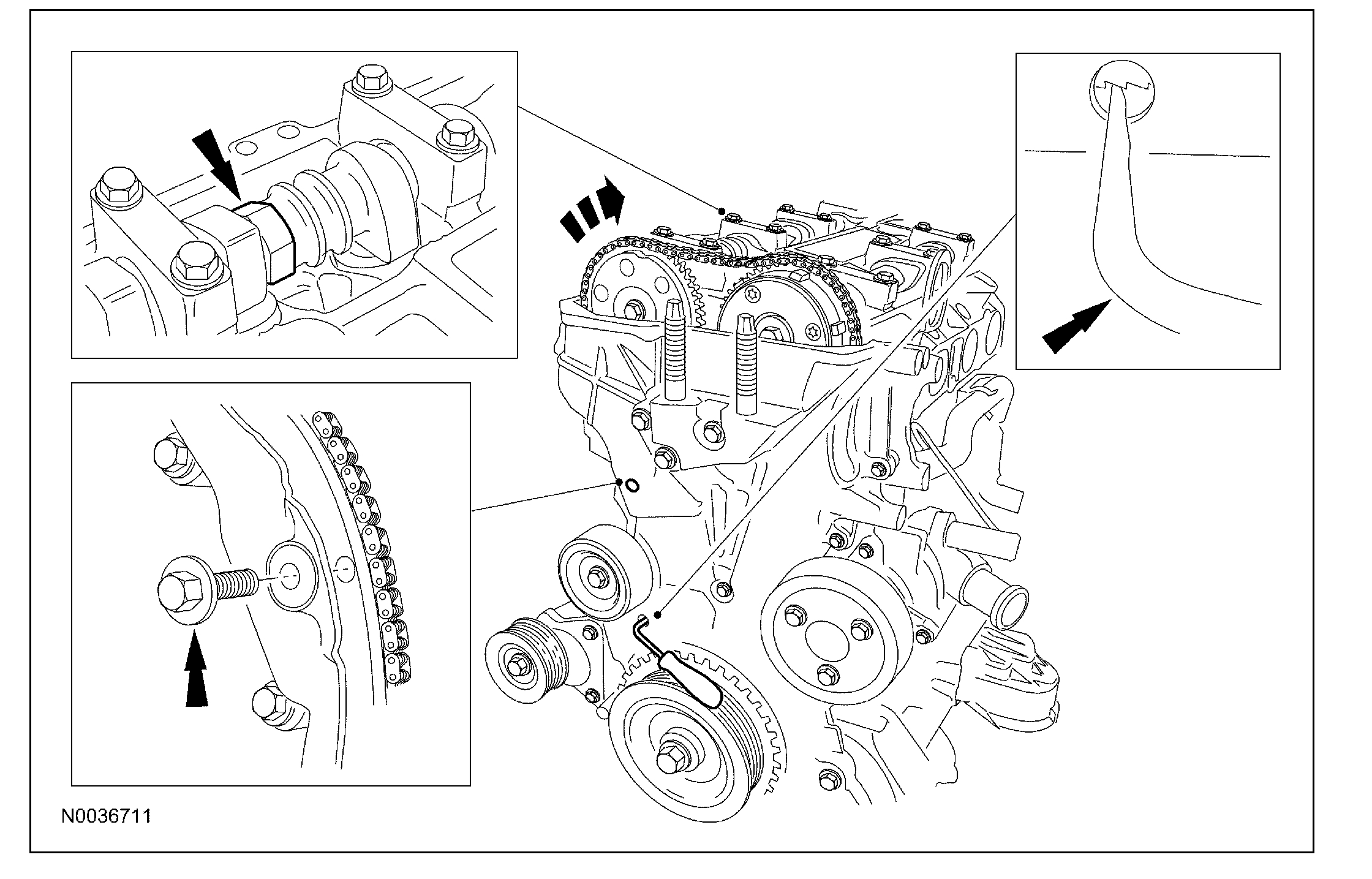
14. NOTE: Releasing the ratcheting mechanism in the timing chain tensioner allows the plunger to collapse and create slack in the timing chain. Installing an M6 x 30 mm (1.18 in) bolt into the upper front cover timing hole will hold the tensioner arm in a retracted position and allow enough slack in the timing chain for removal of the exhaust camshaft gear.
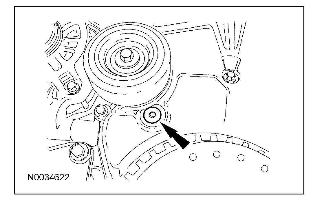
Using a small pick tool, unlock the chain tensioner ratchet through the lower front cover timing hole.
Using the flats of the camshaft, have an assistant rotate the exhaust camshaft clockwise to collapse the timing chain tensioner plunger.
Insert an M6 x 30 mm (1.18 in) bolt into the upper front cover timing hole to hold the tensioner arm in place.
15. Remove the special tool.
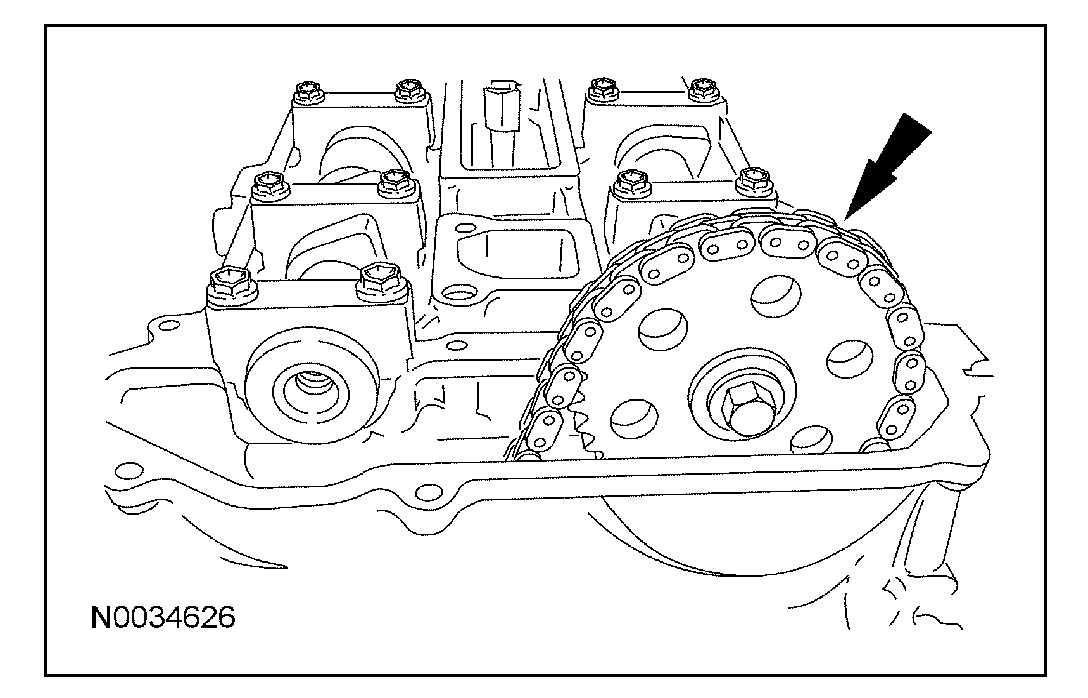
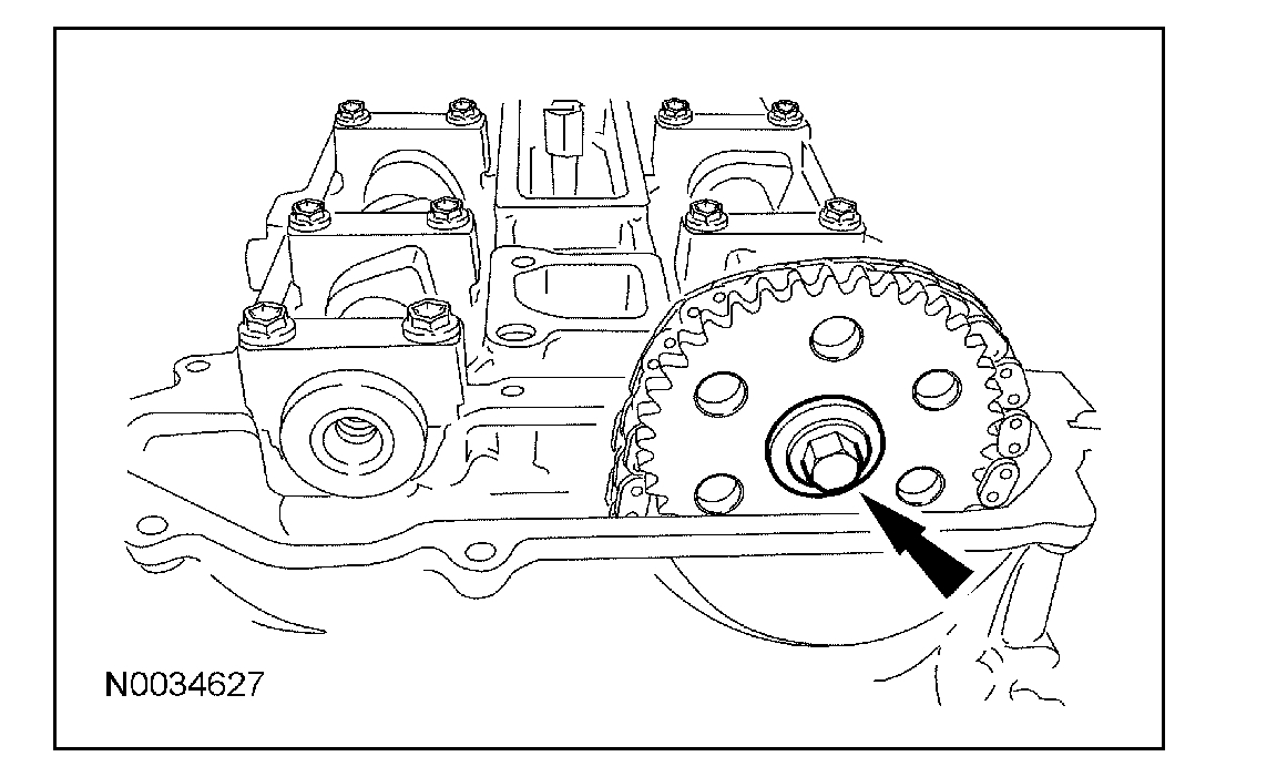
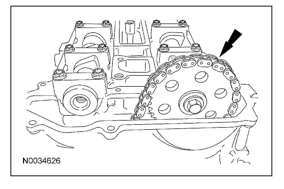
16. Using the flats on the camshaft to prevent camshaft rotation, remove the bolt and exhaust camshaft drive gear.
17. Remove the timing chain from the intake camshaft drive gear.
18. Using the flats on the camshaft to prevent camshaft rotation, remove the bolt and intake camshaft drive gear.
19. Mark the position of the camshaft lobes on the No. 1 cylinder for installation reference.
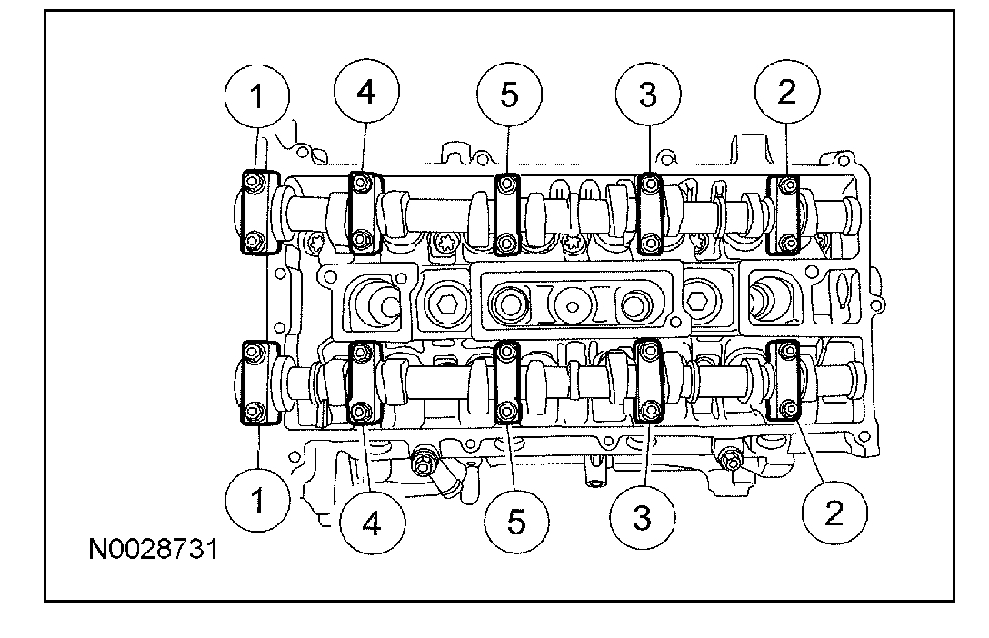
20. CAUTION: Failure to follow the camshaft loosening procedure can result in damage to the camshafts.
NOTE: Mark the location and orientation of each camshaft bearing cap.
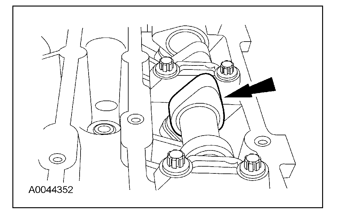
Remove the camshafts from the engine.
Loosen the camshaft bearing cap bolts, in sequence, one turn at a time.
Repeat the first step until all tension is released from the camshaft bearing caps.
Remove the camshaft bearing caps.
Remove the camshafts.
Installation
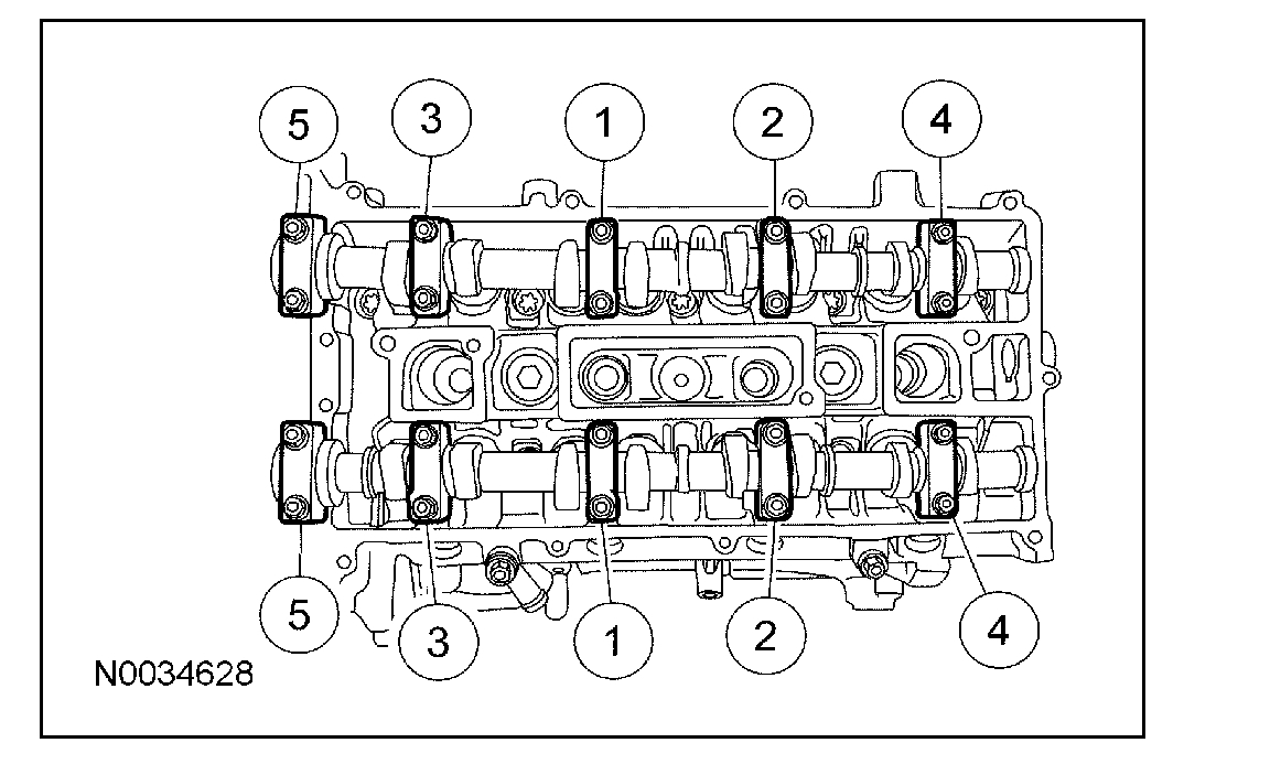
1. CAUTION: Install the camshafts with the alignment slots in the camshafts lined up so the Camshaft Alignment Plate can be installed without rotating the camshafts. Make sure the lobes on the No. 1 cylinder are in the same position as noted in the removal procedure. Rotating the camshafts when the timing chain is removed, or installing the camshafts 180 degrees out of position can cause severe damage to the valves and pistons.
NOTE: Lubricate the camshaft journals and bearing caps with clean engine oil.
Install the camshafts and bearing caps in their original location and orientation. Tighten the bearing caps in the sequence shown in 3 stages:
Stage 1: Tighten the camshaft bearing cap bolts one turn at a time until finger tight.
Stage 2: Tighten to 7 Nm (62 lb-in).
Stage 3: Tighten to 16 Nm (12 lb-ft).
2. Install the special tool.
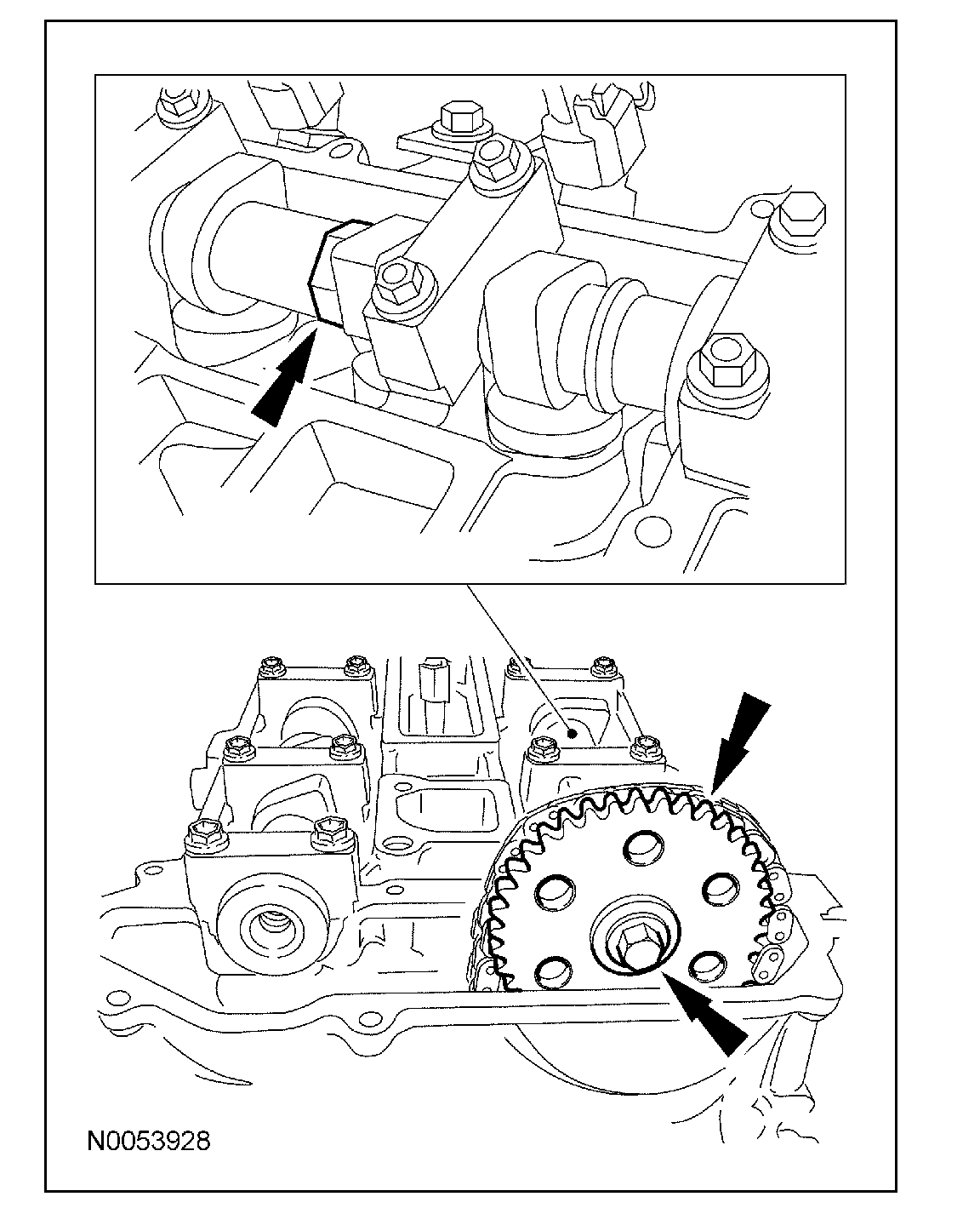
3. Install the intake camshaft drive gear and hand-tighten the bolt.
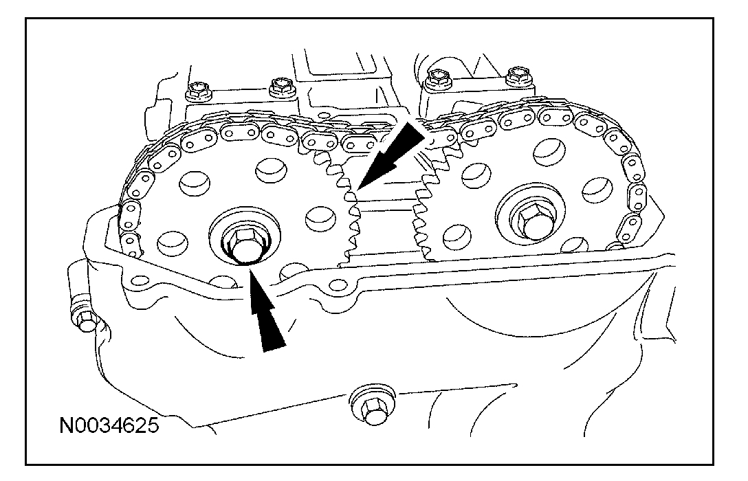
4. Install the timing chain on the intake camshaft drive gear.
5. NOTE: The timing chain must be correctly engaged on the teeth of the crankshaft timing sprocket and the intake camshaft drive gear in order to install the exhaust camshaft drive gear onto the exhaust camshaft.
Position the exhaust camshaft drive gear in the timing chain and install the gear and bolt on the exhaust camshaft.
Hand-tighten the bolt.
6. NOTE: Releasing the tensioner arm will remove the slack from the timing chain release.
Remove the M6 x 30 mm bolt from the upper front cover timing hole to unlock the tensioner arm.
7. CAUTION: The special tool (303-465) is for camshaft alignment only. Using this tool to prevent engine rotation can result in engine damage.
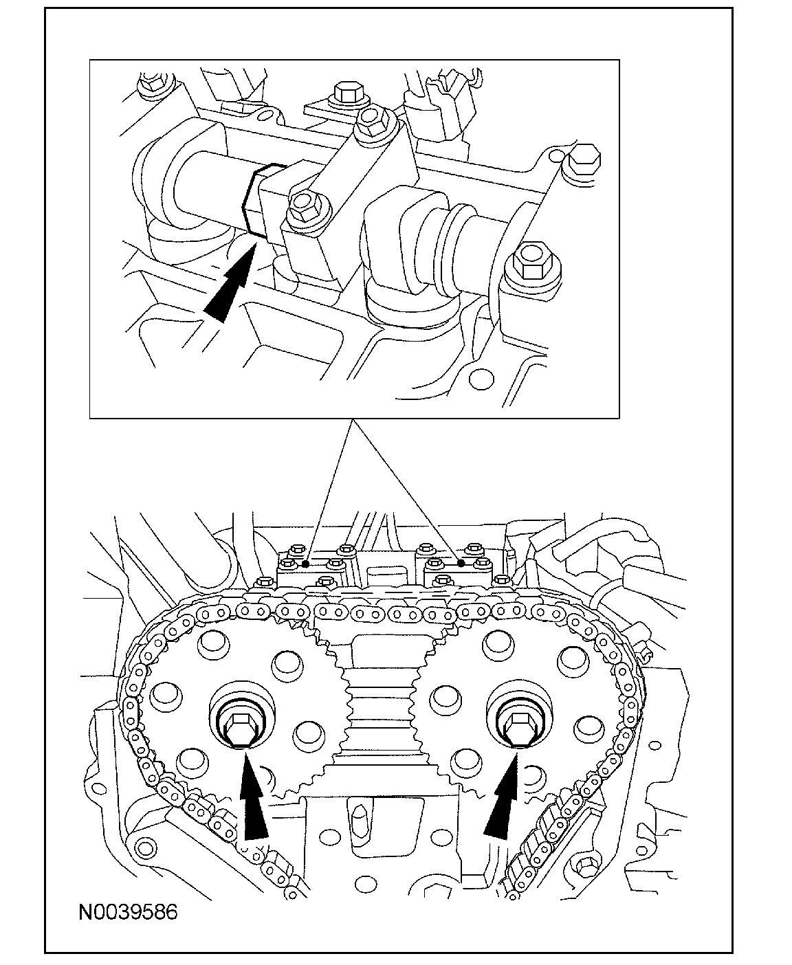
Using the flats on the camshafts to prevent camshaft rotation, tighten the camshaft drive gear bolts.
Tighten to 72 Nm (53 lb-ft).
8. Remove the special tool.
9. Remove the 6 mm (0.23 in) x 18 mm (0.7 in) bolt.
10. Remove the special tool.
11. Install the front cover upper timing hole plug.
Tighten to 10 Nm (89 lb-in).
12. Apply silicone gasket and sealant to the threads of the front cover lower timing hole plug.
Install the plug and tighten to 12 Nm (9 lb-ft).
13. Install the engine plug bolt.
Tighten to 20 Nm (15 lb-ft).
14. Install the accessory drivebelt.
15. Install the RF wheel and tire.
16. Install the valve cover.
17. Install the coolant expansion tank.
________________________
Let me know what you find.
Joe
Images (Click to make bigger)
Sunday, November 11th, 2018 AT 5:55 PM