Good afternoon,
I attached the procedure and some pictures for you for the procedure.
The intake manifold must be removed to gain access to the valve covers.
Roy
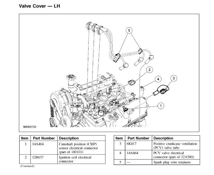
Left half
Removal and Installation
1. Remove the intake manifold.
2. Disconnect the camshaft position (CMP) sensor electrical connector.
3. Disconnect the ignition coil electrical connector. Detach the wiring harness retainer.
4. Disconnect the fuel injector electrical connectors. Detach the wiring harness retainers.
imageOpen In New TabZoom/Print
5. Remove the positive crankcase ventilation (PCV) valve tube.
6. Disconnect the PCV valve electrical connector.
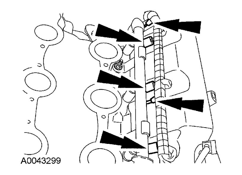
7. Detach the spark plug wire retainers.
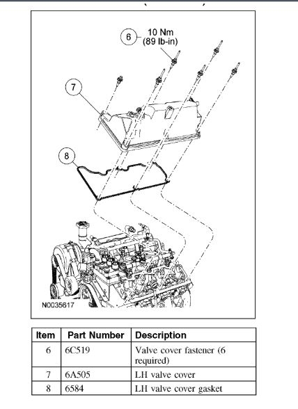
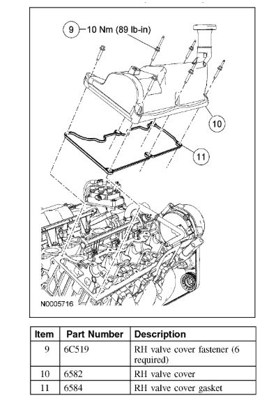
8. Remove the bolts and the valve cover.
To install, tighten to 10 Nm (89 inch lbs.).
9. CAUTION: Do not use metal scrapers, wire brushes, power abrasive discs or other abrasive means to clean sealing surfaces. These tools cause scratches and gouges which make leak paths. Use a plastic scraping tool to remove all traces of the old valve cover gasket.
Clean and inspect the sealing surfaces and the gasket. Install a new gasket if necessary.
10. To install, reverse the removal procedure.
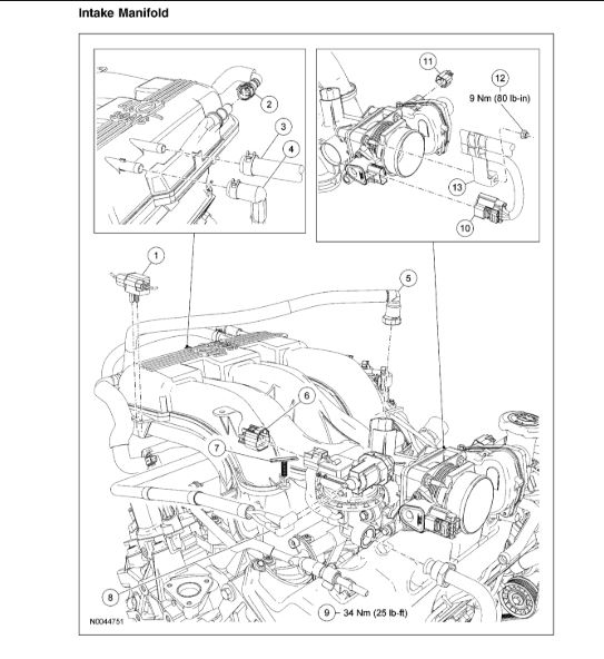
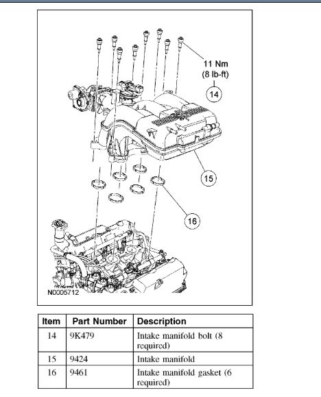
Intake manifold
Removal and Installation
1. Remove the air cleaner outlet pipe.
2. Detach the knock sensor (KS) electrical connector from the intake manifold.
3. Disconnect the positive crankcase ventilation (PCV) tube from the intake manifold.
4. Disconnect the brake booster vacuum hose from the intake manifold.
5. Disconnect the main vacuum harness fitting from the intake manifold.
6. Disconnect the evaporative emissions (EVAP) tube from the intake manifold.
7. Disconnect the exhaust gas recirculation (EGR) system module electrical connector.
8. Detach the wiring harness retainer.
9. Disconnect the EGR system module vacuum fitting.
10. Loosen the fitting and disconnect the exhaust manifold-to-EGR system module tube from the EGR system module.
To install, tighten to 34 Nm (25 ft. lbs.).
11. Disconnect the throttle position (TP) sensor electrical connector.
12. Disconnect the electronic throttle body (TB) electrical connector.
13. Remove the nut and detach the wiring harness bracket from the electronic TB.
To install, tighten to 9 Nm (80 inch lbs.).
14. Remove the bolts, the intake manifold and the gaskets.
To install, tighten to 11 Nm (8 ft. lbs.).
15. CAUTION: Do not use metal scrapers, wire brushes, power abrasive discs or other abrasive means to clean the sealing surfaces. These tools can cause scratches and gouges which can make leak paths. Use a plastic scraping tool to remove all traces of the old intake manifold gaskets
Clean the sealing surfaces and inspect the gaskets. Install new gaskets if necessary.
16. To install, reverse the removal procedure.
Right half
Removal and Installation
1. Disconnect the spring lock coupling from the fuel supply tube.
2. Remove the intake manifold.
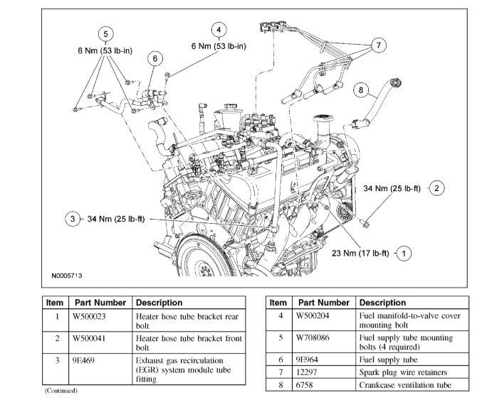
3. Remove the heater hose tube bracket rear bolt.
To install, tighten to 23 Nm (17 ft. lbs.).
4. Remove the heater hose tube bracket front bolt.
To install, tighten to 34 Nm (25 ft. lbs.).
5. Loosen the exhaust manifold-to-exhaust gas recirculation (EGR) system module tube lower fitting and remove the tube.
To install, tighten to 34 Nm (25 ft. lbs.).
6. CAUTION: Use O-ring seals that are made of special fuel-resistant material. Use of ordinary O-ring seals can cause the fuel system to leak.
Remove the fuel supply tube-to-valve cover bracket bolt, the fuel supply tube-to-fuel rail bolts and the fuel supply tube. Remove and discard the O-ring seals.
Install new O-ring seals and lubricate them with clean engine oil.
To install, tighten to 6 Nm (53 inch lbs.).
7. Detach the spark plug wire retainers and position the spark plug wires aside.
8. Remove the crankcase ventilation tube.
9. Remove the bolts and the valve cover.
To install, tighten to 10 Nm (89 inch lbs.).
10. CAUTION: Do not use metal scrapers, wire brushes, power abrasive discs or other abrasive means to clean sealing surfaces. These tools cause scratches which make leak paths. Use a plastic scraping tool to remove all traces of the old valve cover gasket.
Clean and inspect the sealing surfaces and the gasket. Install a new gasket if necessary.
11. To install, reverse the removal procedure.
Images (Click to enlarge)
Jun 9, 2020 at 12:18 PM