Good morning.
That is a self test for the solenoids when the key is turned on.
Do you have an issue with the transmission?
https://www.2carpros.com/articles/automatic-transmission-problems
Roy
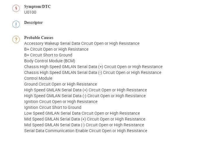
Circuit/System Description
The serial data circuit is the means by which the control modules in the vehicle communicate with each other. Once the scan tool is connected to the serial data circuit through the data link connector (DLC), the scan tool can be used to monitor each control module for diagnostic purposes and to check for diagnostic trouble codes (DTCs). When the ignition switch is in RUN, each control module communicating on the serial data circuit sends a state of health (SOH) message to ensure that the control module is operating properly. When a control module stops communicating on the serial data circuit, for example if the control module loses power or ground, the SOH message it normally sends on the serial data circuit disappears. Other control modules on the serial data circuit, which expect to receive that SOH message, detect its absence; those control modules in turn set a DTC associated with the loss of SOH of the non-communicating control module. The DTC is unique to the control module which is not communicating and one or more control modules may set the same exact code. A loss of serial data communications DTC does not represent a failure of the control modules that contain the stored code.
Conditions for Running the DTC
The system voltage is between 9-16 V.
Conditions for Setting the DTC
A supervised periodic message that includes the transmitter module availability has not been received.
Action Taken When the DTC Sets
Specific subsystems will not function.
DTC U0100 in the TCM will cause the transmission to go into default gears.
Both DTC U0100 in the TCM and DTC U0101 in the ECM will cause the malfunction indicator lamp (MIL) to illuminate.
Conditions for Clearing the DTC
The ECM/TCM module turns OFF the MIL after 4 consecutive ignition cycles that the diagnostic runs and does not fail.
A current DTC clears when the malfunction is no longer present.
A history DTC clears when the module ignition cycle counter reaches the reset threshold of 50, without a repeat of the malfunction.
Diagnostic Aids
Sometimes, while diagnosing a specific customer concern or after a repair, you may notice a history U-code present. However, there is no associated "current" or "active" status. Loss-of- communication U-codes such as these can set for a variety of reasons. Many times, they are transparent to the vehicle operator and technician, and/or have no associated symptoms. Eventually, they will erase themselves automatically after a number of fault-free ignition cycles. This condition would most likely be attributed to one of these scenarios:
A control module on the data communication circuit was disconnected while the communication circuit is awake.
Power to one or more control modules was interrupted during diagnosis.
A low battery condition was present, so some control modules stop communicating when battery voltage drops below a certain threshold.
Battery power was restored to the vehicle and control modules on the communication circuit did not all re-initialize at the same time.
If a loss-of-communication U-code appears in history for no apparent reason, it is most likely associated with one of the scenarios above. These are all temporary conditions and should never be interpreted as an intermittent fault, causing you to replace a part.
A control module may have a U-code stored in history that does not require any repairs. Issues with late or corrupted messages between control modules can be temporary with no apparent symptom or complaint; this does not mean the control module is faulty. Do not replace a control module based only on a history U-code.
Do not replace a control module reporting a U-code. The U-code identifies which control module needs to be diagnosed for a communication issue.
Communication may be available between the BCM and the scan tool with either the low or high speed GMLAN serial data system inoperative. This condition is due to the BCM using both the low and high speed GMLAN systems.
Use Data Link References (See: Information Bus > Initial Inspection and Diagnostic Overview > Data Link References) to determine if the control module uses high or low speed GMLAN serial data communications.
Some control modules may not have internal protection for specific control circuits and may open a B+ or ignition fuse. If a fuse is open and the B+ or ignition circuit is not shorted to ground, ensure none of the control circuits are shorted to ground before replacing the control module.
This diagnostic can be used for any control module that is not communicating, regardless of the type of serial data circuit it is connected to, providing the vehicle is equipped with the control module.
Reference Information
Schematic Reference
Data Communication Schematics (See: Information Bus > Electrical > Data Communication Schematics)
Control Module References (See: Vehicle > Programming and Relearning)
Connector End View Reference
Component Connector End Views (See: Vehicle > Connector Views > Connector End Views By Name)
Description and Operation
Data Link Communications Description and Operation (See: Information Bus > Components Data Link Communications)
Electrical Information Reference
Circuit Testing (See: Vehicle > Component Tests and General Diagnostics > Circuit Testing)
Connector Repairs (See: Vehicle > Component Tests and General Diagnostics > Connector Repairs)
Testing for Intermittent Conditions and Poor Connections (See: Vehicle > Component Tests and General Diagnostics > Testing For Intermittent Conditions and Poor Connections)
Wiring Repairs (See: Vehicle > Component Tests and General Diagnostics > Wiring Repairs)
Scan Tool Reference
Control Module References (See: Vehicle > Programming and Relearning) for scan tool information
Circuit/System Verification
1. Determine the control module that is not communicating. Refer to Control Module U Code List (See: A L L Diagnostic Trouble Codes ( DTC ) > Diagnostic Trouble Code Descriptions > Control Module U Code List).
2. Verify that DTC U0073, U2100, U0074, U1814, U2099, B1428, B1370, B1380, B1440, B1441, B1325, or P0562 is not set.
If any of the DTCs are set, refer to Diagnostic Trouble Code (DTC) List - Vehicle (See: A L L Diagnostic Trouble Codes ( DTC ) > Diagnostic Trouble Code Descriptions > Diagnostic Trouble Code (DTC) List - Vehicle).
3. Engine running for 10 seconds.
4. Ignition ON, engine OFF, verify that DTC U0100-U02FF is not set with symptom byte 00.
If the DTC U0100-U02FF is set with symptom byte 00, refer to Circuit/System Testing.
5. Verify that DTC U0100-U02FF is not set with symptom byte 71 or 72.
If the DTC U0100-U02FF is set with symptom byte 71 or 72 along with other DTCs set, diagnose all other codes first. Refer to Diagnostic Trouble Code (DTC) List - Vehicle (See: A L L Diagnostic Trouble Codes ( DTC ) > Diagnostic Trouble Code Descriptions > Diagnostic Trouble Code (DTC) List - Vehicle).
If the DTC U0100-U02FF is set with symptom byte 71 or 72 and without other DTCs set, reprogram the control module. If the DTC resets, replace the control module.
Circuit/System Testing
Note: Use the schematic to identify the following:
Control modules the vehicle is equipped with
Control module locations on the low and high speed GMLAN serial data circuits
The control modules B+, ignition, ground, communication enable and serial data circuit terminals
1. Ignition OFF, disconnect the harness connector at of the control module that is not communicating.
2. Test for less than 10 ohm between each ground circuit terminal and ground.
If greater than the specified range, test the ground circuit for an open/high resistance.
3. If equipped, ignition ON, verify that a test lamp illuminates between each B+ circuit terminal and ground.
If the test lamp does not illuminate, test the B+ circuit for a short to ground or an open/high resistance. If the circuit fuse is open, test the control circuits of the control module for a short to ground. If the circuits test normal, replace the control module.
4. If equipped, ignition ON, verify that a test lamp illuminates between each ignition circuit terminal and ground.
If the test lamp does not illuminate, test the ignition circuit for a short to ground or an open/high resistance. If the circuit fuse is open, test the control circuits of the control module for a short to ground. If the circuits test normal, replace the control module.
Note: Only the high speed GMLAN modules have a serial data communication enable circuit OR an accessory wakeup serial data circuit, and the body control module is the output for these circuits. Refer to the control module schematics to identify which modules have these circuits.
5. If equipped, ignition ON, verify that a test lamp illuminates between the communication enable circuit terminal OR the accessory wakeup circuit terminal and ground.
If the test lamp does not illuminate, test the entire circuit, including the B+ circuit to the K9 body control module (BCM), for an open/high resistance or short to ground. If the circuits test normal, replace the K9 BCM.
6. Ignition OFF for 60 seconds, test for less than 5 ohm between the serial data circuit terminals and the appropriate X84 data link connector (DLC) terminal listed below:
Class 2 serial data circuit terminal 2
Low speed GMLAN serial data terminal 1
High speed GMLAN serial data terminal 6 or 14
Mid speed GMLAN serial data terminal 3 or 11
Chassis high speed GMLAN serial data terminal 12 or 13
If greater than the specified range, test the serial data circuit for an open/high resistance between the non communicating control module and a module setting the DTC or a serial data splice pack.
7. If all circuits test normal, replace the control module that is not communicating.
Repair Instructions
Perform the Diagnostic Repair Verification (See: A L L Diagnostic Trouble Codes ( DTC ) > Verification Tests > Diagnostic Repair Verification) after completing the diagnostic procedure.
GMLAN Wiring Repairs (See: Vehicle > Component Tests and General Diagnostics > GMLAN Wiring Repairs)
Control Module References (See: Vehicle > Programming and Relearning)for control module replacement, setup, and programming.
Mar 30, 2020 at 7:19 AM