I don't have just a schematic of piping, but I do have the steps for removal and replacement of the turbos. I will attach for both and hopefully, it will provide the info you are looking for.
All attached pictures will correlate with the directions.
____________________
2009 BMW X6 (E71) L6-3.0L Turbo (N54)
11 65 022 Removing and Installing/Replace Exhaust Turbocharger For Cylinders 1-3
Vehicle Powertrain Management Fuel Delivery and Air Induction Turbocharger Service and Repair Removal and Replacement 11 65 022 Removing and Installing/Replace Exhaust Turbocharger For Cylinders 1-3
11 65 022 REMOVING AND INSTALLING/REPLACE EXHAUST TURBOCHARGER FOR CYLINDERS 1-3
11 65 022 - Removing and installing/replacing exhaust-gas turbocharger for cylinders 1-3 (N54)
Necessary preliminary tasks:
- Remove fan cowl with electric fan
- Draining coolant See: Coolant > Procedures
- Remove front right wheel arch trim
- Remove both catalytic exhaust-gas converters
- Remove vacuum unit (wastegate valve) See: Wastegate > Removal and Replacement > 11 65. Removing and Installing Vacuum Unit (Wastegate Valve) For Cylinders 4-6, cylinders 4-6
- Remove right charge-air duct
- Remove air duct See: Air Cleaner Fresh Air Duct/Hose > Removal and Replacement > 13 71 160 Removing and Installing/Replacing Front Air Duct, cylinders 1-3
- Remove coolant thermostat
- Remove coolant pump
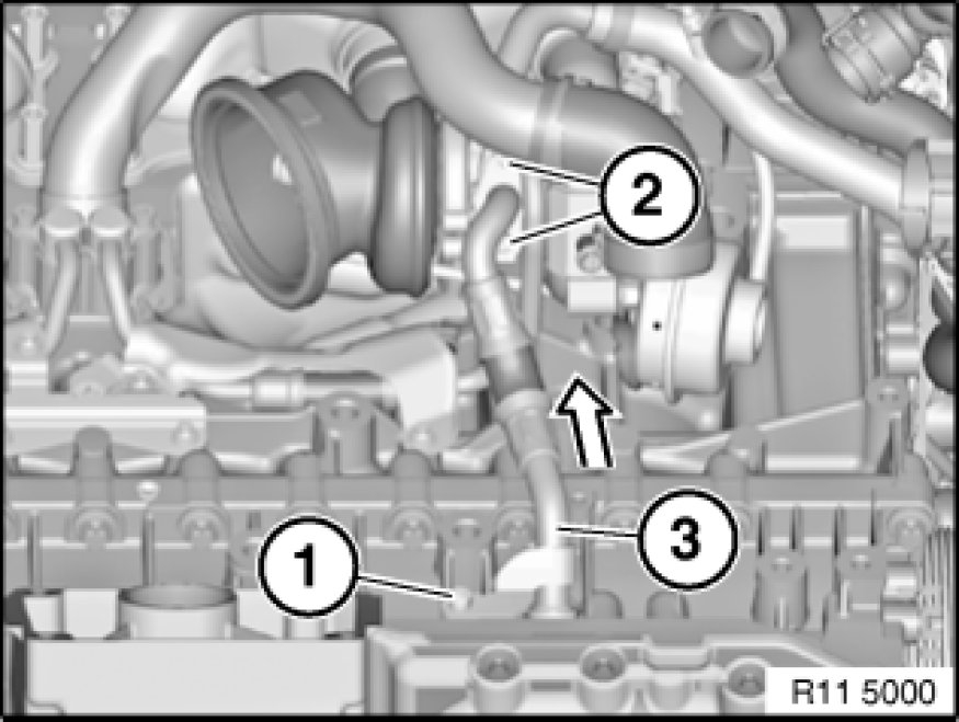
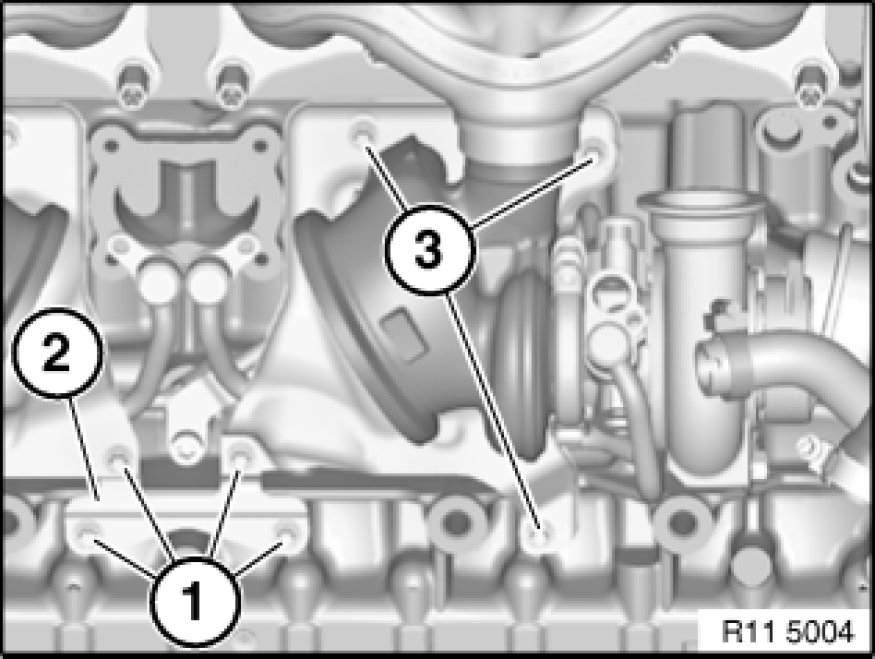
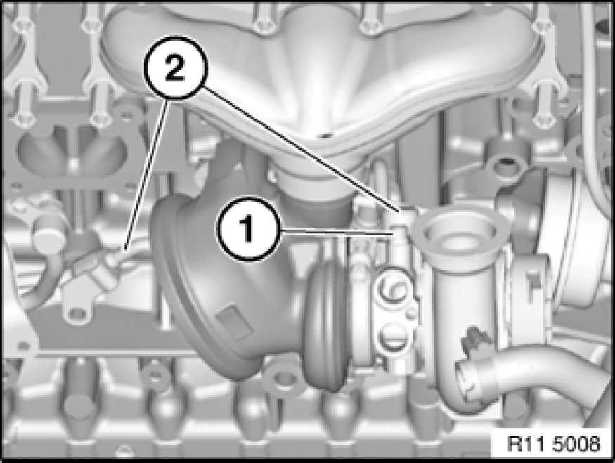
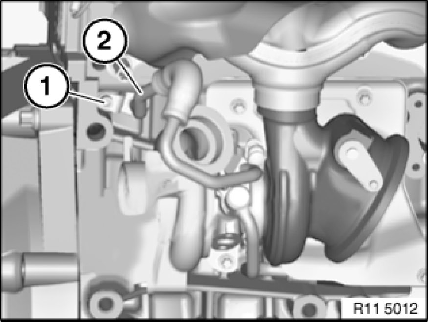
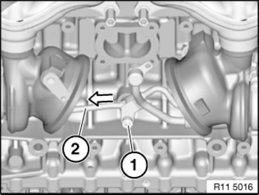
pic 1
Release screws (2).
Tightening torque 11 42 7AZ See: Engine > Mechanical.
Installation:
Replace seal.
Release screw (1).
Tightening torque 11 42 8AZ See: Engine > Mechanical.
Remove oil return line (3) in direction of arrow.
Installation:
Replace O-ring.
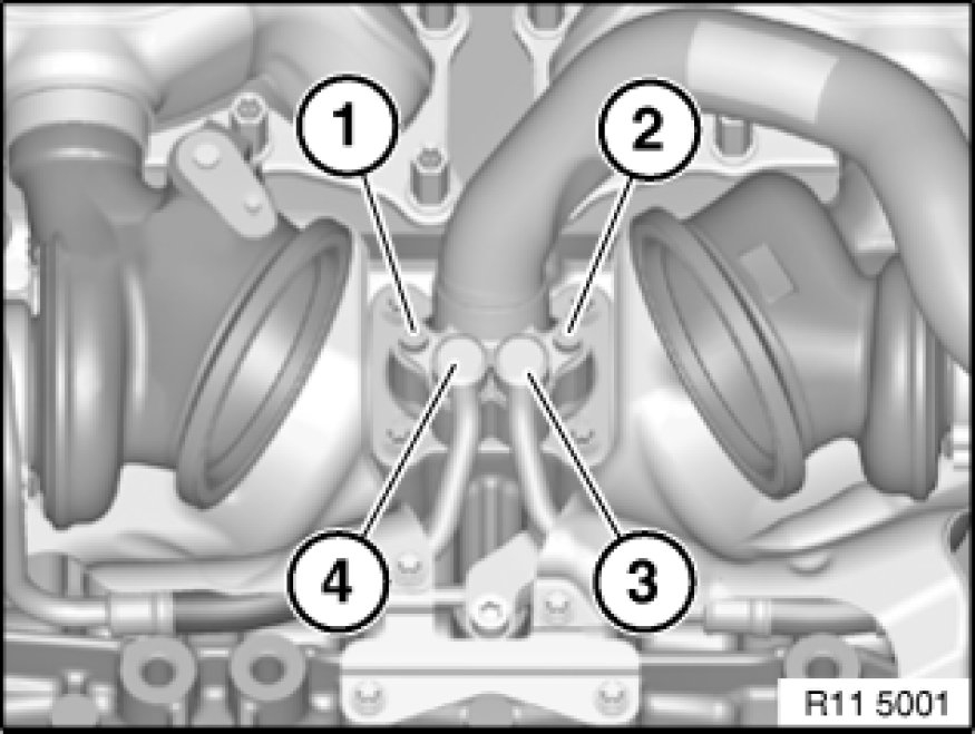
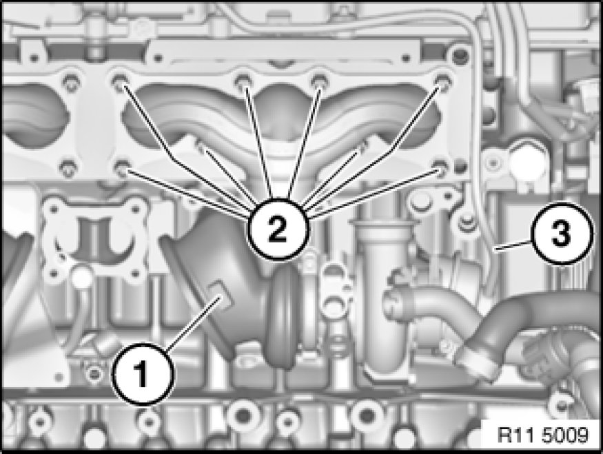
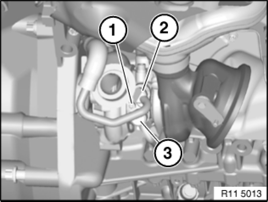
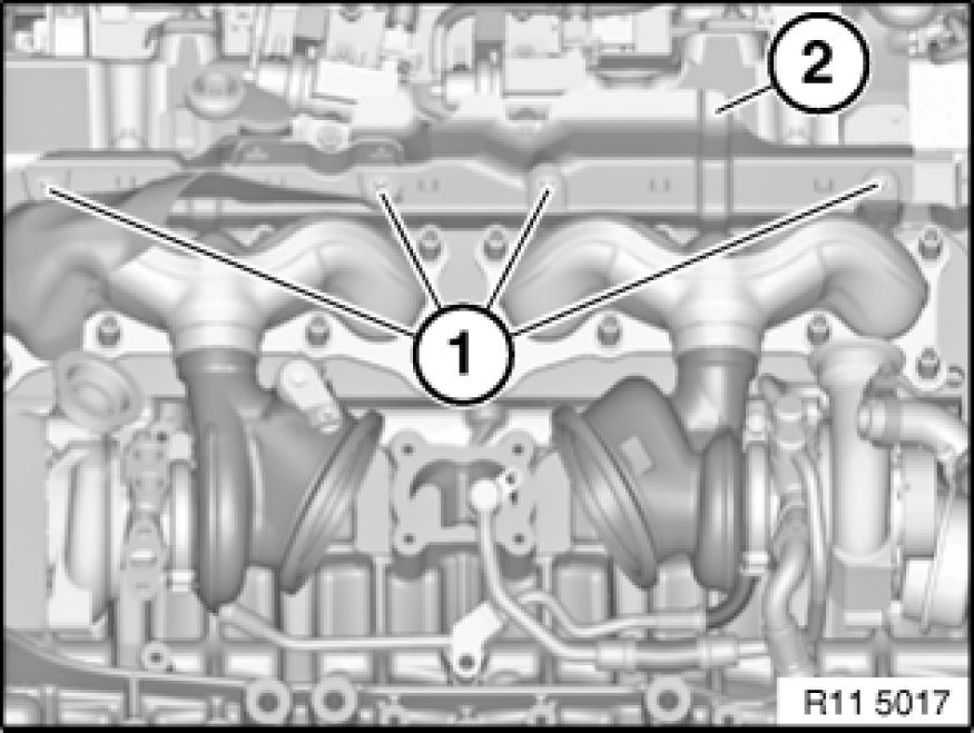
Pic 2
Important!
Where necessary, to release the coolant feed lines (3 and 4), do not place pliers on the pipes.
Risk of damage!
Release screws (1 and 2).
Tightening torque 11 53 10AZ See: Engine > Mechanical.
If necessary, release coolant feed lines (3 and 4) with suitable pliers at connection.
Installation:
Replace O-rings.
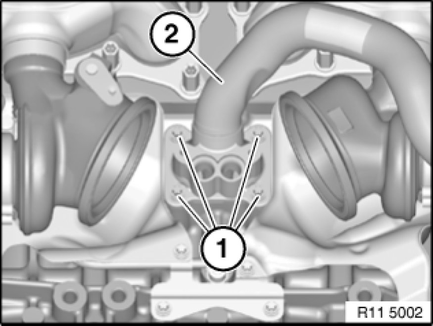
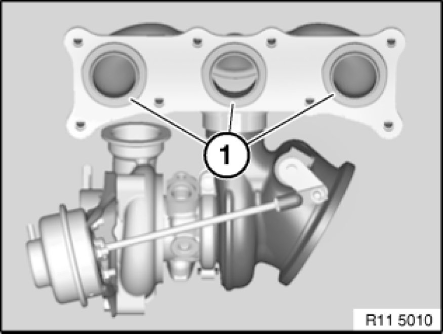
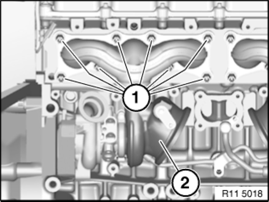
Pic 3
Note:
For purposes of clarity, the graphic shows the released coolant feed lines removed.
Release screws (1).
Tightening torque 11 53 3AZ See: Engine > Mechanical.
Remove feed line (2).
Installation:
Replace seal.
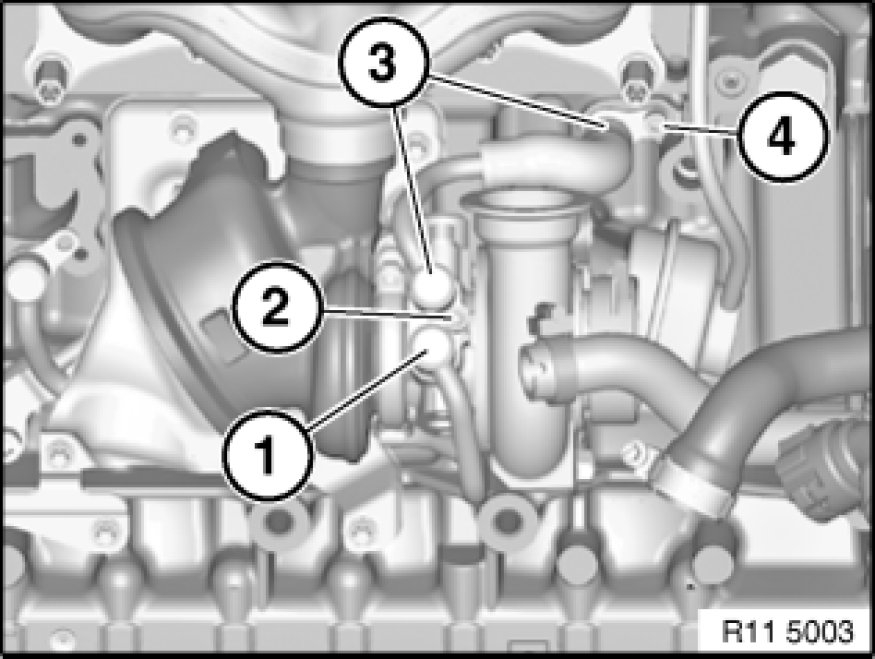
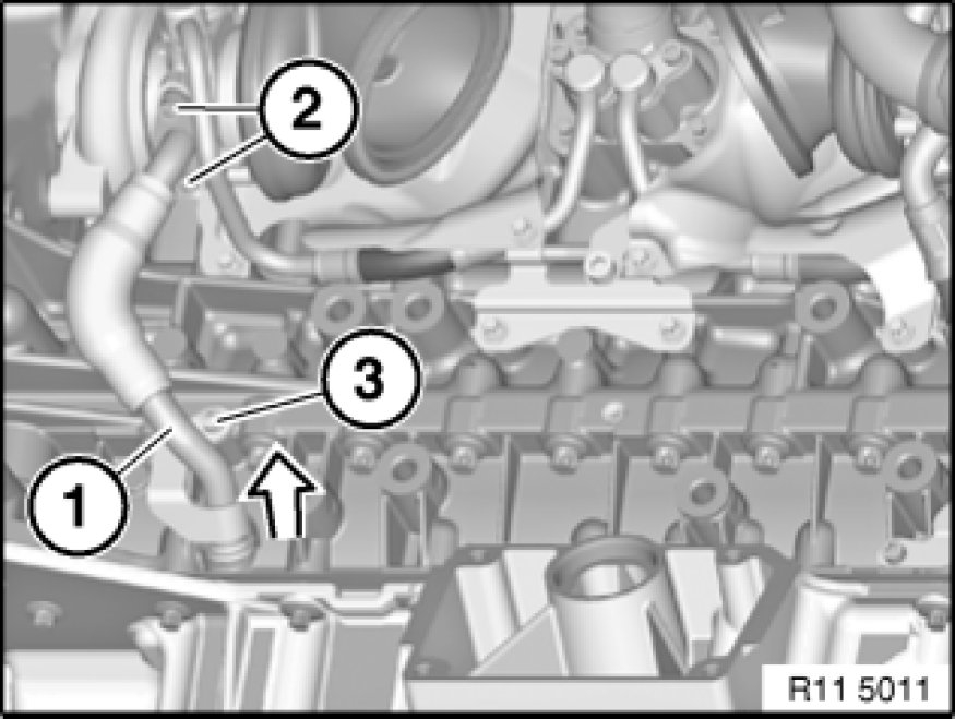
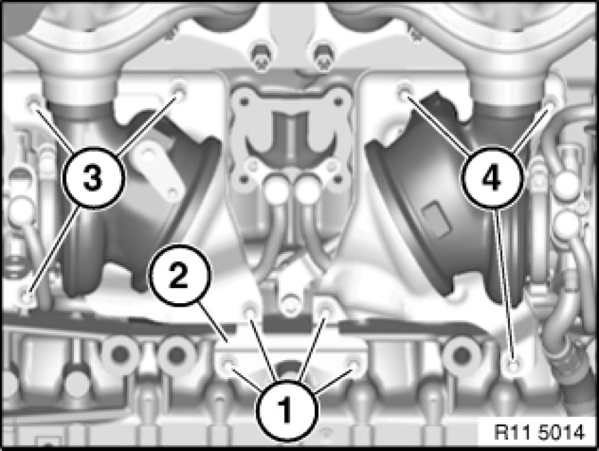
Pic 4
Important!
Where necessary, to release the coolant feed and return lines (1 and 3), do not place pliers on the pipes.
Risk of damage!
Release screw (2).
Tightening torque 11 53 8AZ See: Engine > Mechanical.
If necessary, release coolant feed line (1) with suitable pliers at connection.
Installation:
Replace O-rings.
If necessary, release coolant return line (3) with suitable pliers at front connection.
Release screw (4).
Tightening torque 11 53 9AZ See: Engine > Mechanical.
If necessary, release coolant return line (3) with suitable pliers at rear connection and remove.
Installation:
Replace O-rings.
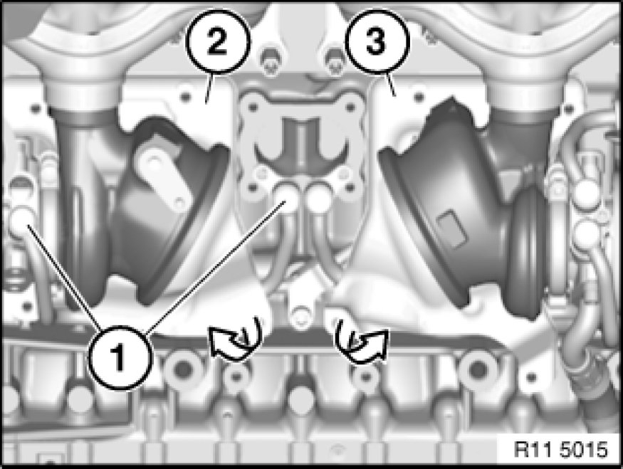
Pic 5
Release screws (1).
Tightening torque 11 65 2AZ See: Engine > Mechanical > 11 65 Turbocharger and Control.
Remove retaining plate (2).
Release screws (3).
Tightening torque 11 65 2AZ See: Engine > Mechanical > 11 65 Turbocharger and Control.
Pic 6
Important!
Carefully swing out heat shield (2) in direction of arrow.
Risk of damage!
Remove heat shield (2) in direction of arrow.
Note:
Coolant feed line (1) can be removed with heat shield (2).
Pic 7
Release screws (1).
Tightening torque 11 65 3AZ See: Engine > Mechanical > 11 65 Turbocharger and Control.
Set holder (2) down on cylinder head cover.
Pic 8
Release screw (1).
Tightening torque 11 42 4AZ See: Engine > Mechanical.
Release oil feed line (2) in direction of arrow.
Installation:
Replace O-ring.
Pic 9
Release screw (1).
Tightening torque 11 42 5AZ See: Engine > Mechanical.
Important!
Where necessary, to release the oil feed line (2), do not place pliers on the pipe.
Risk of damage!
If necessary, release oil feed line (2) with suitable pliers at connection and remove.
Installation:
Replace O-rings.
Pic 10
Detach vacuum hose (3) from vacuum unit (wastegate valve).
Unscrew nuts (2).
Tightening torque 11 65 1AZ See: Engine > Mechanical > 11 65 Turbocharger and Control.
Remove turbocharger (1) towards top.
Important!
Do not misuse linkage of vacuum unit (wastegate valve) to transport turbocharger (1)!
Risk of damage!
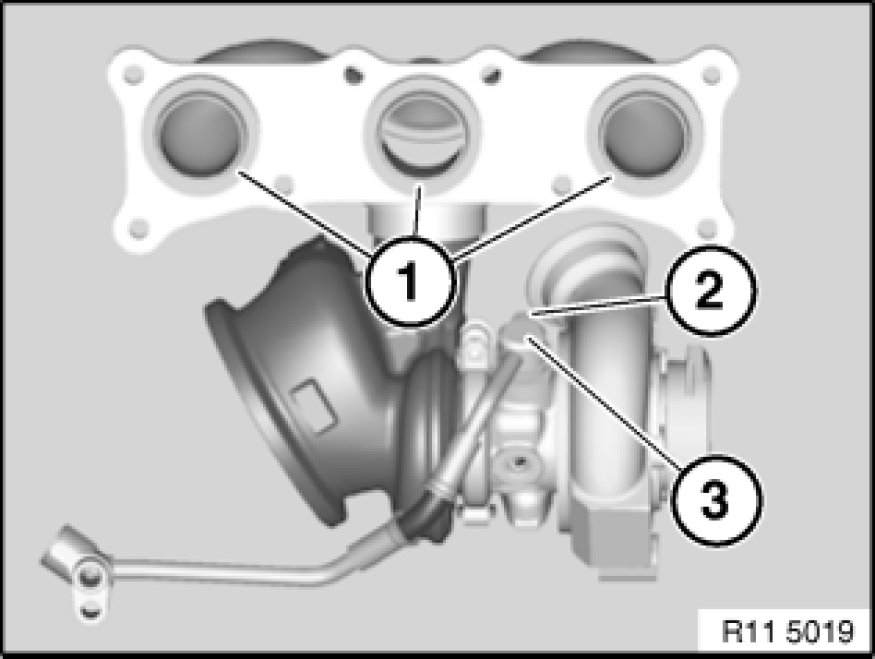
Pic 11
Installation:
Replace graphite sealing rings (1).
Assemble engine.
Clear fault memory in DME control unit.
Carry out BMW leak test See: Fuel Delivery and Air Induction > Component Tests and General Diagnostics > 11 61 730 BMW Leak Test For Intake System for intake system.
Observe DME control unit instructions.
_______________________________________________________________________________
2009 BMW X6 (E71) L6-3.0L Turbo (N54)
11 65 024 Removing and Installing/Replace Exhaust Turbocharger For Cylinders 4-6
Vehicle Powertrain Management Fuel Delivery and Air Induction Turbocharger Service and Repair Removal and Replacement 11 65 024 Removing and Installing/Replace Exhaust Turbocharger For Cylinders 4-6
11 65 024 REMOVING AND INSTALLING/REPLACE EXHAUST TURBOCHARGER FOR CYLINDERS 4-6
11 65 024 - Removing and installing/replacing exhaust-gas turbocharger for cylinders 4-6 (N54)
Necessary preliminary tasks:
- Remove fan cowl with electric fan
- Draining coolant See: Coolant > Procedures
- Remove front right wheel arch trim
- Remove both catalytic exhaust-gas converters
- Remove vacuum unit (wastegate valve) See: Wastegate > Removal and Replacement > 11 65. Removing and Installing Vacuum Unit (Wastegate Valve) For Cylinders 4-6, cylinders 4-6
- Remove right charge-air duct
- Remove air duct See: Air Cleaner Fresh Air Duct/Hose > Removal and Replacement > 13 71 160 Removing and Installing/Replacing Front Air Duct, cylinders 1-3
- Remove air duct, cylinders 4-6
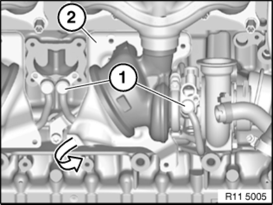
pic 12
Release screws (2).
Tightening torque 11 42 7AZ See: Engine > Mechanical.
Installation:
Replace seal.
Unscrew bolt (3).
Tightening torque 11 42 8AZ See: Engine > Mechanical.
Remove oil return line (1) in direction of arrow.
Installation:
Replace O-ring.
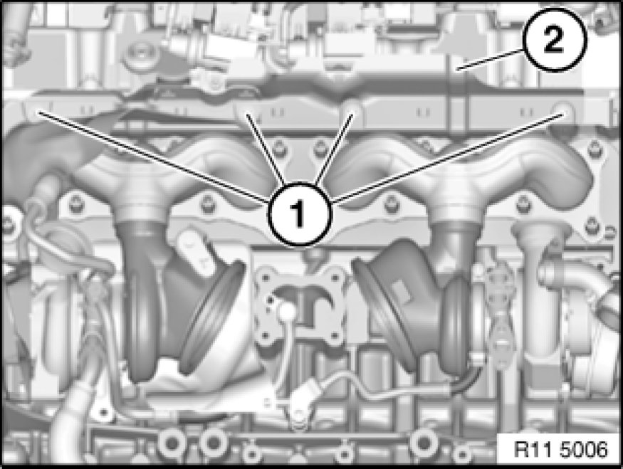
Pic 13
Important!
Where necessary, to release the coolant feed lines (3 and 4), do not place pliers on the pipes.
Risk of damage!
Release screws (1 and 2).
Tightening torque 11 53 10AZ See: Engine > Mechanical.
If necessary, release coolant feed lines (3 and 4) with suitable pliers at connection.
Installation:
Replace O-rings.
Pic 14
Note:
For purposes of clarity, the graphic shows the released coolant feed lines removed.
Release screws (1).
Tightening torque 11 53 3AZ See: Engine > Mechanical.
Remove feed line (2).
Installation:
Replace seal.
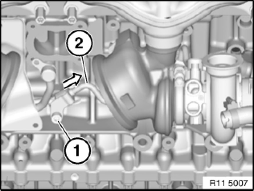
Pic 15
Important!
Where necessary, to release the coolant return line (2), do not place pliers on the pipe.
Risk of damage!
Release screw (1).
Tightening torque 11 53 9AZ See: Engine > Mechanical.
If necessary, release coolant return line (2) with suitable pliers at connection.
Installation:
Replace O-ring.
Pic 16
Important!
Where necessary, to release the coolant feed and return lines (2 and 3), do not place pliers on the pipes.
Risk of damage!
Release screw (1).
Tightening torque 11 53 8AZ See: Engine > Mechanical.
If necessary, release coolant feed line (3) with suitable pliers at connection.
Installation:
Replace O-rings.
If necessary, release coolant return line (2) with suitable pliers at connection and remove.
Installation:
Replace O-rings.
Pic 17
Release screws (1).
Tightening torque 11 65 2AZ See: Engine > Mechanical > 11 65 Turbocharger and Control.
Remove retaining plate (2).
Unfasten screws (3 and 4).
Tightening torque 11 65 2AZ See: Engine > Mechanical > 11 65 Turbocharger and Control.
Pic 18
Important!
Carefully swing out heat shields (2 and 3) in direction of arrow.
Risk of damage!
Remove heat shield (3) in direction of arrow.
Remove heat shield (2) in direction of arrow.
Note:
Coolant feed line (1) can be removed with heat shield (2).
Pic 19
Release screw (1).
Tightening torque 11 42 4AZ See: Engine > Mechanical.
Release oil feed line (2) in direction of arrow.
Installation:
Replace O-ring.
Pic 20
Release screws (1).
Tightening torque 11 65 3AZ See: Engine > Mechanical > 11 65 Turbocharger and Control.
Set holder (2) down on cylinder head cover.
Pic 21
Unscrew nuts (1).
Tightening torque 11 65 1AZ See: Engine > Mechanical > 11 65 Turbocharger and Control.
Remove turbocharger (2) downwards.
Pic 22
Release screw (2).
Tightening torque 11 42 5AZ See: Engine > Mechanical.
Important!
Where necessary, to release the oil feed line (3), do not place pliers on the pipe.
Risk of damage!
If necessary, release oil feed line (3) with suitable pliers at connection and remove.
Installation:
Replace O-rings.
Installation:
Replace graphite sealing rings (1).
Assemble engine.
Clear fault memory in DME control unit.
Carry out BMW leak test See: Fuel Delivery and Air Induction > Component Tests and General Diagnostics > 11 61 730 BMW Leak Test For Intake System for intake system.
Observe DME control unit instructions.
Let me know if this helps.
Joe
Images (Click to make bigger)
Thursday, February 13th, 2020 AT 7:43 PM