Good morning again.
This is for the TPS. If you had it off, make sure you installed it correctly or it will code.
Roy
Related Links
General Information
Description
Background
When a Diagnostic Trouble Code (DTC) 121, 124 or 125 are set in continuous memory, the technician is directed to Pinpoint Test G of the Powertrain Control/Emissions Diagnosis (PC/ED) Manual. Pinpoint Test G is named: In-Range MAF/TP/Fuel lnjector Pulse Width Test. The description of the test is as follows:
EEC-IV DTC Code 121, 124, and 125 Description.
This In-Range Self-Test was designed to identify in-range concerns of the MAF sensor, TP sensor, or the fuel delivery system. The PCM will use information from these three (3) areas based on vehicle load to generate three (3) independent values. The three (3) independent values will be continuously monitored by the PCM. If one (1) of the values differs significantly from the others during normal vehicle operation, a Continuous Memory Diagnostic Trouble Code (DTC) will be stored.
EEC codes for the TPS are intended as a supplemental aid to diagnostics. They do not indicate the root cause since more than one (1) component can set the same code.
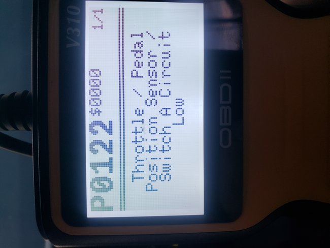
For example: EEC-IV, OBD I Codes 122 and 123 and EEC-V, OBD II Codes P0122 and P0123 for "TP circuit too low" or "TP circuit too high", limit the condition to the TP circuit, connector, or vehicle harness.
EEC-IV, OBD I Codes: 121, "TP inconsistent with air meter", 124, "TP higher than expected", 125, "TP lower than expected" and OBD II Code P1121, "TP inconsistent with MAF sensor" are a result of a comparison of the TP signal to a given airflow. Any un-metered air (downstream of MAF) that enters the engine, either due to a mechanical situation or electrical sensor condition, may result in these codes. PC/ED Pinpoint Tests will guide you to the root cause and avoid customer repeat repairs.
EEC-IV (OBD I) Codes 124 and 125 are set in memory as follows: Codes 124-125 are a comparison of a given airflow to the TPS voltage (throttle plate position).
Code 124: The PCM has indicated that the airflow rate is too low for the position of the throttle plate angle.
Causes for EEC-IV, OBD I Code 124:
Air bypass solenoid flow low/blocked (MAF may indicate low during the event).
Throttle body obstructed.
EGR flow low.
TPS circuit concern when accompanied by Codes 122 or 123.
BP sensor low.
Code 125: The PCM has indicated that the airflow rate is too high for the position of the throttle plate.
Causes of EEC-IV, OBD I Code 125:
Air bypass solenoid high/stuck open (MAF may indicate high during this event).
EGR flow high.
TPS circuit concern when accompanied by Codes 122 or 123.
BP sensor high.
These codes are designed to set while in the part throttle drive mode, and often the MIL light flashes on and off until the condition is gone. In some cases, it is difficult to repeat the codes in a test drive since the PCM requires a long drive time to calculate the error in the system. At other times, it may be difficult to repeat because the condition that set the code may be intermittent. Pinpoint Test G of the PC/ED Manual will guide you to the root cause.
Causes of EEC Codes 122: TPS sensor circuit voltage above maximum.
Causes of EEC codes 123: TPS sensor circuit voltage below minimum.
Harness damage.
Connector damage or water in connector.
Defective TPS, open or short.
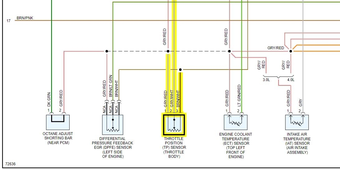
Check VREF for correct output.
Throttle plate not closing.
TPS
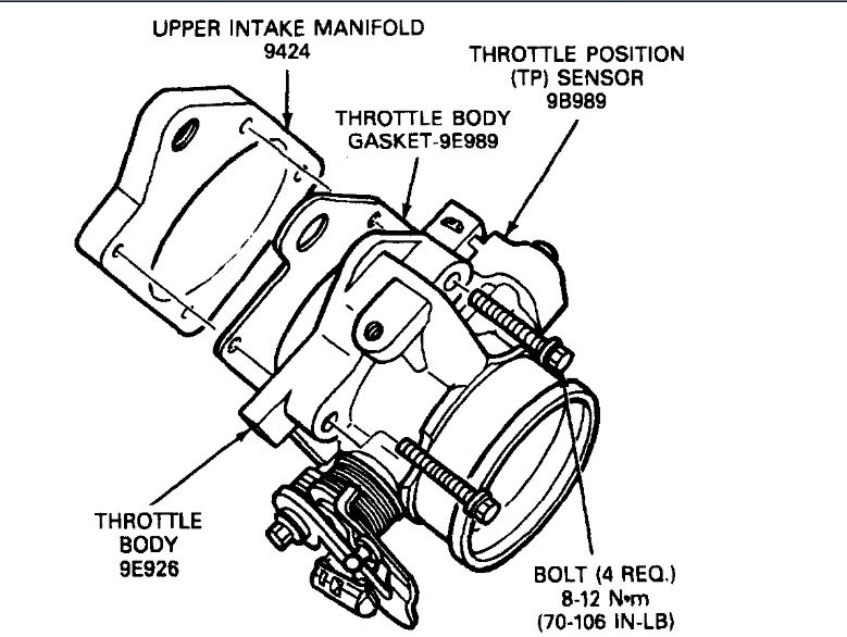
REMOVAL
1. Disconnect Throttle Position (TP) sensor electrical connector engine control sensor wiring.
2. Remove the two throttle position sensor retaining screws.
3. Remove the throttle position sensor and throttle position sensor gasket.
INSTALLATION
1. Position the throttle position sensor on the throttle body. Make sure that rotary tangs on sensor are in proper alignment with the throttle shaft blade.
NOTE: This throttle position sensor is non-adjustable.
2. Secure throttle position sensor to throttle body with two retaining screws. Tighten to 3-4 Nm (28-35 lb in).
3. Connect electrical connector to the throttle position sensor.
Image (Click to make bigger)
Thursday, May 28th, 2020 AT 3:34 PM