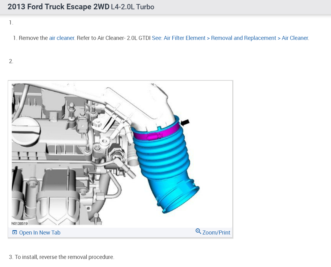
I think you may have a turbo that has gone bad, I would remove the intake and outlet tube to check the turbo endplay and if excessive replace the turbo, I am not sure about the vacuum bleed but I did find this test procedure for the system.
https://www.2carpros.com/articles/how-turbo-chargers-work
HN16 CHECK TURBOCHARGER PRESSURE WASTEGATE ACTUATOR OPERATION
NOTICE:Do not exceed 103.4 kPa (15 psi) of pressure applied to the turbocharger actuators, excessive pressure will damage the actuators.
- Disconnect the turbocharger wastegate control hose from the turbocharger wastegate actuator.
- Record each of the turbocharger wastegate actuator linkage positions.
- Using a suitable hand pump with pressure gauge, pressurize the turbocharger wastegate actuator to 48.3 kPa (7 psi).
Does each turbocharger wastegate actuator linkage move from the starting position and does the pressure remain steady?
Yes
- GO to HN17.
No
- GO to HN18.
HN1 CHECK FOR DIAGNOSTIC TROUBLE CODES (DTCS)
Note:This pinpoint test is designed to diagnose multiple components in the same test steps, only measure the circuits that apply to the vehicle and component being diagnosed.
Note:Diagnose circuit concerns prior to range or performance concerns.
Are DTCs P0034, P0035, P00C1, P00C2, P0234, P0245, P0246, P0299, P100F, P1011, P1012, P1013, P1014, P1015 or P1016 present?
Yes
- GO to HN2.
No
- For symptoms without DTCs, GO to HN12.
- For all others, RETURN to Section 3 See: Computers and Control Systems > Diagnostic Trouble Code Tests and Associated Procedures > SECTION 3: Symptom Charts, Symptom Charts for further direction.
HN2 VISUALLY INSPECT THE TURBOCHARGER SYSTEM
- Visually inspect the turbocharger system for:
- correct vacuum supply system hose connections and routing
- correct vacuum turbocharger wastegate control hose connection and routing
- correct pressure turbocharger wastegate control hose connection and routing
- correct vacuum turbocharger bypass control hose connection and routing
- leaks around tubing and intake manifold
- correct electrical connections
- damaged or leaking exhaust system
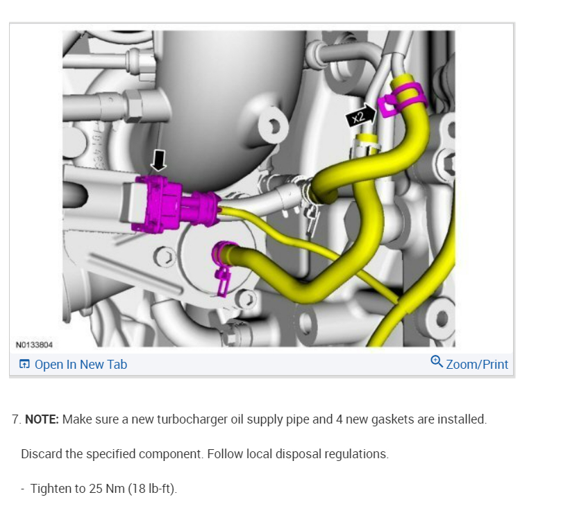
- turbocharger oil leaks. Refer to Fuel Delivery and Air Induction, Fuel Charging and Controls - Turbocharger.
- damaged or restricted turbocharger oil return tubes. Refer to Fuel Delivery and Air Induction, Fuel Charging and Controls - Turbocharger.
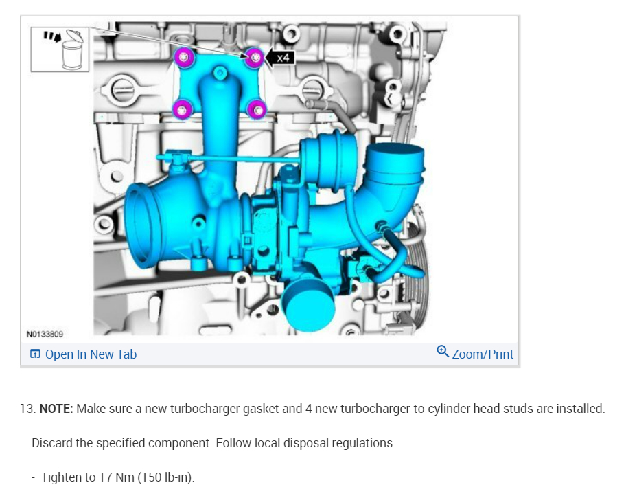
- damaged turbocharger. Refer to Fuel Delivery and Air Induction, Fuel Charging and Controls - Turbocharger.
Do the visual inspections reveal any concerns?
Yes
- REPAIR as necessary.
- Clear the PCM DTCs. REPEAT the self-test.
No
- For DTC P100F only, GO to HN3.
- For DTC P1011, P1012, P1013, P1014, P1015 or P1016. GO to HN4.
- For all others, GO to HN5.
HN3 SENSOR CORRELATION
- Ignition ON, engine OFF.
- Access the PCM and monitor the BARO (PRESS), MAP (PRESS), TCBP (PRESS) and WGATE_PRES (PRESS) PIDs.
Is the WGATE_PRES PID reading within 6.77 kPa (0.98 psi) of the other PID readings?
Yes
- GO to HN5.
No
- CHECK the turbocharger wastegate vacuum system hoses for restrictions. REPAIR as necessary.
- If no concerns are present, INSTALL a new Wastegate Vacuum Sensor.
- Clear the PCM DTCs. REPEAT the self-test.
HN4 CHECK FOR VREF AT THE SENSOR
- Ignition OFF.
- Wastegate Vacuum Sensor connector disconnected.
- Ignition ON, engine OFF.
- Measure the voltage between:
Is the voltage between 4.5 - 5.5 V?
Yes
- GO to HN6.
No
- GO to Pinpoint Test C See: Computers and Control Systems > Diagnostic Trouble Code Tests and Associated Procedures > C: Reference Voltage (VREF) - Introduction.
HN5 CHECK FOR VOLTAGE AT THE COMPONENT
Note:This step applies to multiple components, only measure the circuits that apply to the vehicle and component being diagnosed.
- Ignition OFF.
- For TCBY,
- TCBY Valve connector disconnected.
- Ignition ON, engine OFF.
- Measure the voltage between:
- For TCBY2,
- TCBY2 connector disconnected.
- Ignition ON, engine OFF.
- Measure the voltage between:
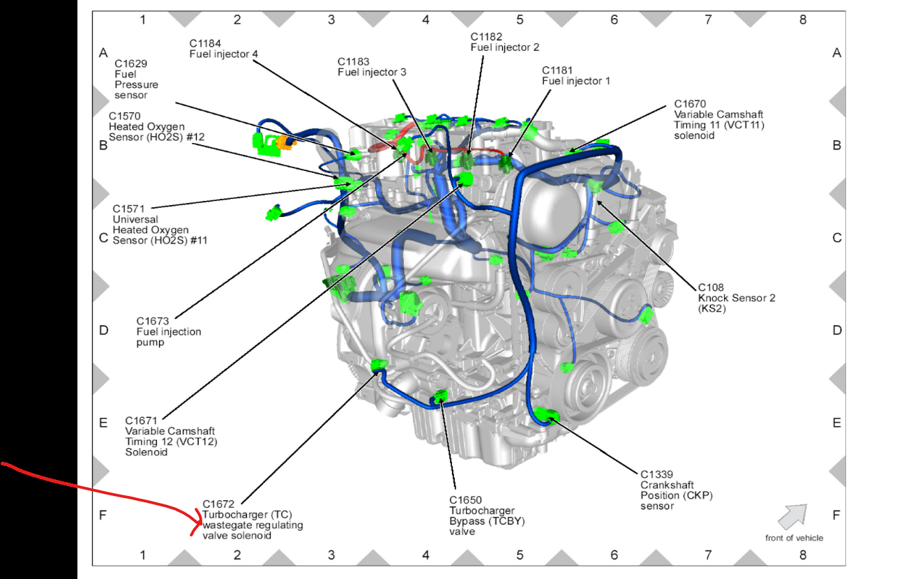
- For turbocharger wastegate regulating valve solenoid,
- Turbocharger Wastegate Regulating Valve Solenoid connector disconnected.
- Ignition ON, engine OFF.
- Measure the voltage between:
Is the voltage greater than 10.5 V?
Yes
- GO to HN6.
No
- REPAIR the open circuit. Clear the PCM DTCs. REPEAT the self-test.
HN6 CHECK FOR AN OPEN
Note:This step applies to multiple components, only measure the circuits that apply to the vehicle and component being diagnosed.
- Ignition OFF.
- PCM connector disconnected.
- For TCBY,
- Measure the resistance between:
- For TCBY2,
- Measure the resistance between:
- For turbocharger wastegate regulating valve solenoid,
- Measure the resistance between:
- For wastegate vacuum sensor,
- Measure the resistance between:
Are the resistances less than 5 ohms?
Yes
- GO to HN7.
- REPAIR the open circuit. Clear the PCM DTCs. REPEAT the self-test.
HN7 CHECK FOR A SHORT TO GROUND
Note:This step applies to multiple components, only measure the circuits that apply to the vehicle and component being diagnosed.
- Ignition OFF.
- For TCBY,
- Measure the resistance between:
For TCBY2,
- Measure the resistance between:
- For turbocharger wastegate regulating valve solenoid,
- Measure the resistance between:
- For wastegate vacuum sensor,
- Measure the resistance between:
Is the resistance greater than 10K ohms?
Yes
- GO to HN8.
No
- REPAIR the short circuit. Clear the PCM DTCs. REPEAT the self-test.
HN8 CHECK FOR A SHORT TO VOLTAGE
Note:This step applies to multiple components, only measure the circuits that apply to the vehicle and component being diagnosed.
- Ignition ON, engine OFF.
- For TCBY,
- Measure the voltage between:
- For TCBY2,
- Measure the voltage between:
- For turbocharger wastegate regulating valve solenoid,
- Measure the voltage between:
- For wastegate vacuum sensor,
- Measure the voltage between:
Is any voltage present?
Yes
- REPAIR the short circuit. Clear the PCM DTCs. REPEAT the self-test.
No
- For DTCs P1011, P1012, P1013, P1014, P1015 or P1016, GO to HN10.
- For all others, GO to HN9.
HN9 CHECK THE COMPONENT RESISTANCE
Note:This step applies to multiple components, only measure the circuits that apply to the vehicle and component being diagnosed.
- Ignition OFF.
- For TCBY,
- Measure the resistance between:
- For TCBY2,
- Measure the resistance between:
Turbocharger Bypass Valve Solenoid Resistance
- For turbocharger wastegate regulating valve solenoid,
- Measure the resistance between:
Turbocharger Wastegate Regulating Valve Solenoid Resistance
Is the resistance within specification?
Yes
- GO to HN10.
No
- INSTALL a new suspect component. REFER to Computers and Control Systems Electronic Engine Controls.
- Clear the PCM DTCs. REPEAT the self-test.
HN10 CHECK THE WIRING HARNESS
Note:This step applies to multiple components, only measure the circuits that apply to the vehicle and component being diagnosed.
- Ignition OFF.
- PCM connector connected.
- For TCBY or TCBY2,
- Suspect TCBY Solenoid connector connected.
- Ignition ON, engine OFF.
- Access the PCM and monitor the TURBO_BP1_STAT (MODE) PID.
- Access the PCM and monitor the TURBO_BP2_STAT (MODE) PID.
- For the turbocharger wastegate regulating valve solenoid,
- Turbocharger Wastegate Regulating Valve Solenoid connector connected.
- Ignition ON, engine OFF.
- Access the PCM and monitor the TWGATE_STAT (MODE) PID.
- For wastegate vacuum sensor,
- Wastegate Vacuum Sensor connector connected.
- Ignition ON, engine OFF.
- Access the PCM and monitor the WGATE_PRES_F (MODE) PID.
- While observing the PID, wiggle, shake, and bend small sections of the wiring harness while working from the component to the PCM.
Is there a change in the PID reading?
Yes
- ISOLATE the concern. REPAIR as necessary.
- Clear the PCM DTCs. REPEAT the self-test.
No
- GO to HN11.
HN11 INTERMITTENT CHECK
Note:This step applies to multiple components, only measure the circuits that apply to the vehicle and component being diagnosed.
- For TCBY or TCBY2,
- Access the PCM and monitor the TURBO_BP1_STAT (MODE) PID.
- Access the PCM and monitor the TURBO_BP2_STAT (MODE) PID.
- For the turbocharger wastegate regulating valve solenoid,
- Access the PCM and monitor the TWGATE_STAT (MODE) PID.
- For wastegate vacuum sensor,
- Access the PCM and monitor the WGATE_PRES_F (MODE) PID.
- While observing the PID, carry out the following:
- lightly tap on the suspect component to simulate road shock
- wiggle the suspect component connector
Is there a change in the PID reading?
Yes
- INSTALL a new suspect component. REFER to Computers and Control Systems Electronic Engine Controls.
- Clear the PCM DTCs. REPEAT the self-test.
No
- For DTCs P1011, P1015 or P1016, GO to HN27.
- For all others, GO to HN12.
HN12 TURBOCHARGER SYSTEM PERFORMANCE CONCERNS
Note:For a performance concern related to a plugged or restricted exhaust, GO to HF8 See: Computers and Control Systems > Diagnostic Trouble Code Tests and Associated Procedures > HF: Catalyst Efficiency Monitor and Exhaust Systems - Pinpoint Test.
Note:Diagnose circuit concerns prior to range or performance concerns.
Note:Visually inspect the vehicle for aftermarket accessories and performance modifications (exhaust system, turbocharger, performance chip). Refer to Section 1 Engine Control (EC) System See: Computers and Control Systems > Diagnostic Trouble Code Tests and Associated Procedures > Engine Control (EC) System, Modifications to OBD Vehicles.
- Ignition OFF.
- Check the air filter element and housing for contamination, blockage or water intrusion.
- Disconnect the air intake and check for restrictions and water intrusion.
- Visually inspect the turbocharger system for:
- correct vacuum supply system hose connections and routing
- correct vacuum turbocharger wastegate control hose connection and routing
- correct pressure turbocharger wastegate control hose connection and routing
- correct vacuum turbocharger bypass control hose connection and routing
- leaks around tubing and intake manifold
- correct electrical connections
- damaged or leaking exhaust system
- turbocharger oil leaks. Refer to Fuel Delivery and Air Induction, Fuel Charging and Controls - Turbocharger.
- damaged or restricted turbocharger oil return tubes. Refer to Fuel Delivery and Air Induction, Fuel Charging and Controls - Turbocharger.
- damaged turbocharger. Refer to Fuel Delivery and Air Induction, Fuel Charging and Controls - Turbocharger.
- Check the charge air cooler (CAC) system for leaks (hoses and cooler).
- Check the CAC and intake air system for restrictions.
- Check for aftermarket exhaust accessories and performance modifications.
- Visually inspect the exhaust system for the following:
- leaks, cracks, or punctures upstream of turbocharger
- aftermarket accessories and performance modifications
- tailpipe modifications that increase the exhaust restriction
- plugged or restricted exhaust
Is a concern present?
Yes
- REPAIR as necessary.
- Clear the PCM DTCs. REPEAT the self-test.
No
- GO to HN13.
HN13 CHECK THE CHARGE AIR COOLER (CAC) AND INTAKE AIR SYSTEMS FOR LEAKS AND RESTRICTIONS
Note:Remember to reinstall the sensor, reconnect the CAC tube to the throttle body and remove the plastic bag from the air filter at the completion of this step.
- Disconnect the CAC tube from the throttle body.
- Use a suitable method to temporarily plug the CAC tube outlet.
- Place the air filter in a plastic bag to prevent air flow out the intake port and reinstall it in the vehicle.
- Remove the IAT or TCIPT sensor from the ducting between the air filter housing and the turbocharger.
- Connect the Rotunda Smoke Machine, Fuel Evaporative Emission System Tester 218-00001 (522) or equivalent to the intake air system using an appropriate adapter.
- Fill the intake air system with smoke.
- Check the intake air system for leaks and restrictions.
Are any leaks or restrictions present?
Yes
- REPAIR as necessary.
- Clear the PCM DTCs. REPEAT the self-test.
No
- GO to HN14.
HN14 CHECK BYPASS VALVE OPERATION
Note:For vehicles without a commendable RPM PID, use the accelerator pedal to hold the engine RPM at approximately 2,000 RPM.
Note:The TCBP PID value may decrease by 0.97 KPa (0.14 psi) or less when the TCBY valve is commanded ON.
- Ignition ON, engine running.
- Access the PCM and control the TURBO_BPASS (MODE) PID.
- Access the PCM and control the TURBO_BPASS_2 (MODE) PID.
- Command the TURBO_BPASS PID and the TURBO_BPASS_2 PID to OFF.
- Access the PCM and control the TURBO_WGATE (PER) PID.
- Command the TURBO_WGATE PID duty cycle to 0%.
- Access the PCM and monitor the TCBP (PRESS) PID.
- Access the PCM and control the RPM (RPM) PID.
- Command the RPM PID to the maximum RPM.
- Record the TCBP PID reading.
- Command the TURBO_BPASS and the TURBO_BPASS_2 PIDs ON and record the TCBP PID reading.
Does the TCBP PID reading decrease when the bypass valves are commanded ON?
Yes
- GO to HN15.
No
- For Edge 2.0L,
- Escape/Kuga 2.0L,
- Explorer 2.0L,
- Focus 2.0L GTDI,
- Fusion 2.0L,
- MKT 2.0L, and
- Taurus 2.0L, GO to HN19.
- For all others, INSTALL a new Suspect TCBY solenoid.
- REFER to Computers and Control Systems Electronic Engine Controls.
- Clear the PCM DTCs. REPEAT the self-test.
HN15 CHECK WASTEGATE OPERATION
Note:For vehicles without a commendable RPM PID, use the accelerator pedal to hold the engine RPM at approximately 2,000 RPM.
- Ignition ON, engine running.
- Access the PCM and control the TURBO_BPASS (MODE) PID.
- Access the PCM and control the TURBO_BPASS_2 (MODE) PID.
- Command the TURBO_BPASS PID and the TURBO_BPASS_2 PID to OFF.
- Access the PCM and control the TURBO_WGATE (PER) PID.
- Command the TURBO_WGATE PID duty cycle to 0%.
- Access the PCM and monitor the TCBP (PRESS) PID.
- Access the PCM and control the RPM (RPM) PID.
- Command the RPM PID to the maximum RPM.
- Record the TCBP PID reading.
- Command the TURBO_WGATE PID duty cycle to 100% and record the TCBP PID reading.
Does the TCBP PID reading increase when the TURBO_WGATE PID duty cycle is commanded to 100%?
Yes
- GO to HN26.
No
- For Edge 2.0L, and
- Explorer 2.0L, GO to HN22.
- For all others, GO to HN16.
HN16 CHECK TURBOCHARGER PRESSURE WASTEGATE ACTUATOR OPERATION
NOTICE:Do not exceed 103.4 kPa (15 psi) of pressure applied to the turbocharger actuators, excessive pressure will damage the actuators.
- Disconnect the turbocharger wastegate control hose from the turbocharger wastegate actuator.
- Record each of the turbocharger wastegate actuator linkage positions.
- Using a suitable hand pump with pressure gauge, pressurize the turbocharger wastegate actuator to 48.3 kPa (7 psi).
Does each turbocharger wastegate actuator linkage move from the starting position and does the pressure remain steady?
Yes
- GO to HN17.
No
- GO to HN18.
HN17 CHECK PRESSURE SYSTEM TO THE TURBOCHARGER WASTEGATE ACTUATOR
NOTICE:Do not exceed 103.4 kPa (15 psi) of pressure applied to the turbocharger actuators, excessive pressure will damage the actuators.
- Disconnect the pressure supply hose from the inlet of the turbocharger wastegate regulating valve solenoid.
- Disconnect the pressure control hose from the outlet of the turbocharger wastegate regulating valve solenoid.
- Using a suitable adaptor, connect the pressure supply hose to the pressure control hose.
- Disconnect the turbocharger wastegate pressure supply hose from the high pressure tube.
- Using a suitable hand pump with pressure gauge, pressurize the turbocharger wastegate pressure supply hose to 48.3 kPa (7 psi).
Does each turbocharger wastegate actuator linkage move from the starting position and does the pressure remain steady?
Yes
- INSTALL a new Turbocharger Wastegate Regulating Valve solenoid.
- REFER to Fuel Delivery and Air Induction, Fuel Charging and Controls, Turbocharger.
- Clear the PCM DTCs. REPEAT the self-test.
No
- A pressure system leak or restriction is the cause of the concern.
DIAGNOSE the turbocharger wastegate pressure system leak or restriction.
- REPAIR as necessary.
- Clear the PCM DTCs. REPEAT the self-test.
HN18 CHECK THE TURBOCHARGER WASTEGATE ACTUATOR LINKAGE FOR DAMAGE OR OBSTRUCTIONS
- Attempt to manually activate the suspect actuator.
Can the suspect actuator be activated manually?
Yes
- INSTALL a new turbocharger wastegate actuator. REFER to Fuel Delivery and Air Induction, Fuel Charging and Controls.
- Clear the PCM DTCs. REPEAT the self-test.
No
- Visually inspect the suspect turbocharger wastegate actuator linkage for damage or obstructions. Repair as necessary.
- If no turbocharger wastegate actuator linkage concerns are
present, INSTALL a new turbocharger assembly. Refer to Fuel Delivery and Air Induction, Fuel Charging and Controls.
- Clear the PCM DTCs. REPEAT the self-test.
HN19 CHECK THE TURBOCHARGER BYPASS VALVE SOURCE VACUUM
- Disconnect the vacuum supply tube from the vacuum pump.
- Using the DSL ENG Pressure Test Kit 014-00761 or equivalent, measure the vacuum at the vacuum pump.
- Ignition ON, engine running.
- Record the vacuum.
Is the vacuum greater than 33.86 kPa (10 in-Hg)?
Yes
- GO to HN20.
No
- DIAGNOSE a loss of vacuum. REFER to Brakes and Traction Control, Brake System.
- Clear the PCM DTCs. REPEAT the self-test.
HN20 CHECK THE BYPASS VALVE
- Disconnect the vacuum control tube from the TCBY valve.
- Using the DSL ENG Pressure Test Kit 014-00761 or equivalent, apply 33.86 kPa (10 in-hg) of vacuum to the TCBY valve.
Does the vacuum remain steady?
Yes
- GO to HN21.
No
- INSTALL a new TCBY valve.
- REFER to Fuel Delivery and Air Induction, Fuel Charging and Controls, Turbocharger.
- Clear the PCM DTCs. REPEAT the self-test.
HN21 CHECK THE VACUUM SYSTEM
- Disconnect the vacuum supply tube from the inlet of the TCBY solenoid.
- Disconnect the vacuum control tube from the outlet of the TCBY solenoid.
- Using a suitable adaptor, connect the vacuum supply tube to the vacuum control tube.
- Disconnect the vacuum supply tube from the vacuum pump.
- Using the DSL ENG Pressure Test Kit 014-00761 or equivalent, apply 33.86 kPa (10 in-hg) of vacuum to the vacuum supply tube.
Does the vacuum remain steady?
Yes
- INSTALL a new TCBY solenoid.
- REFER to Fuel Delivery and Air Induction, Fuel Charging and Controls, Turbocharger.
- Clear the PCM DTCs. REPEAT the self-test.
No
- A vacuum system leak or restriction is the cause of the concern.
DIAGNOSE the vacuum system leak or restriction. REPAIR as necessary.
- Clear the PCM DTCs. REPEAT the self-test.
HN22 CHECK THE TURBOCHARGER WASTEGATE SOURCE VACUUM
- Disconnect the vacuum supply tube from the vacuum pump.
- Using the DSL ENG Pressure Test Kit 014-00761 or equivalent, measure the vacuum at the vacuum pump.
- Ignition ON, engine running.
- Record the vacuum.
Is the vacuum greater than 33.86 kPa (10 in-Hg)?
Yes
- GO to HN23.
No
- DIAGNOSE a loss of vacuum. REFER to Brakes and Traction Control, Brake System.
- Clear the PCM DTCs. REPEAT the self-test.
HN23 CHECK TURBOCHARGER VACUUM WASTEGATE ACTUATOR OPERATION
- Disconnect the turbocharger wastegate control hose from the turbocharger wastegate actuator.
- Record each of the turbocharger wastegate actuator linkage positions.
- Using the DSL ENG Pressure Test Kit 014-00761 or equivalent, apply 33.86 kPa (10 in-hg) of vacuum to the turbocharger wastegate actuator.
Does each turbocharger wastegate actuator linkage move from the starting position and does the pressure remain steady?
Yes
- GO to HN24.
No
- GO to HN25.
HN24 CHECK THE VACUUM SUPPLY HOSE FROM THE VACUUM PUMP TO THE TURBOCHARGER WASTEGATE ACTUATOR
- Disconnect the vacuum supply hose from the inlet of the turbocharger wastegate regulating valve solenoid.
- Disconnect the vacuum control hose from the outlet of the turbocharger wastegate regulating valve solenoid.
- Using a suitable adaptor, connect the vacuum supply hose to the vacuum control hose.
- Disconnect the turbocharger wastegate vacuum supply hose from the vacuum pump.
- Using the DSL ENG Pressure Test Kit 014-00761 or equivalent, apply 33.86 kPa (10 in-hg) of vacuum to the vacuum supply hose.
Does each turbocharger wastegate actuator linkage move from the starting position and does the vacuum remain steady?
Yes
- INSTALL a new Turbocharger Wastegate Regulating Valve solenoid.
- REFER to Fuel Delivery and Air Induction, Fuel Charging and Controls, Turbocharger.
- Clear the PCM DTCs. REPEAT the self-test.
No
- A vacuum system leak or restriction is the cause of the concern.
DIAGNOSE the turbocharger wastegate vacuum system leak or restriction.
- REPAIR as necessary.
- Clear the PCM DTCs. REPEAT the self-test.
HN25 CHECK THE TURBOCHARGER WASTEGATE ACTUATOR LINKAGE FOR DAMAGE OR OBSTRUCTIONS
- Attempt to manually activate the suspect actuator.
Can the suspect actuator be activated manually?
Yes
- INSTALL a new turbocharger wastegate actuator. REFER to Fuel Delivery and Air Induction, Fuel Charging and Controls, Turbocharger.
- Clear the PCM DTCs. REPEAT the self-test.
No
- Visually inspect the suspect turbocharger wastegate actuator linkage for damage or obstructions. Repair as necessary.
- If no turbocharger wastegate actuator linkage concerns are
present, INSTALL a new turbocharger assembly. REFER to Fuel Delivery and Air Induction, Fuel Charging and Controls, Turbocharger.
- Clear the PCM DTCs. REPEAT the self-test.
HN26 TURBOCHARGER COMPRESSOR WHEEL CHECK
- Inspect the turbocharger compressor wheel and housing for the following:
- ability to spin freely
- noise while spinning
- damage to vanes on the compressor wheel
- out of balance condition
- debris in housing
Is a concern present?
Yes
- INSTALL a new suspect turbocharger assembly. REFER to Fuel Delivery and Air Induction, Fuel Charging and Controls, Turbocharger.
- Clear the PCM DTCs. REPEAT the self-test.
No
- GO to HN28.
HN27 CHECK THE WASTEGATE VACUUM SENSOR
- Ignition ON, engine OFF.
- Access the PCM and monitor the WGATE_V (VOLT) PID.
- Record the PID value.
- Disconnect the wastegate vacuum tube from the vacuum port on the turbocharger wastegate vacuum sensor.
- Using a suitable hand pump with gauge, apply 34.47 kPa (5 in-Hg) vacuum to the wastegate vacuum sensor port.
- Record the PID value.
Does the PID value change when vacuum is applied?
Yes
- A vacuum system leak or restriction is the cause of the concern.
DIAGNOSE the vacuum system leak or restriction. REPAIR as necessary.
- Clear the PCM DTCs. REPEAT the self-test.
No
- INSTALL a new Wastegate Vacuum Sensor. REFER to Computers and Control Systems Electronic Engine Controls.
- Clear the PCM DTCs. REPEAT the self-test.
HN28 CHECK FOR CORRECT PCM OPERATION
- Disconnect all the PCM connectors.
- Visually inspect for:
- pushed out pins
- corrosion
- Connect all the PCM connectors and make sure they seat correctly.
- Carry out the PCM self-test.
- Verify the concern is still present.
Is the concern still present?
Yes
- INSTALL a new PCM.
No
- The system is operating correctly at this time. The concern may have been caused by a loose or corroded connector.
Let me know what you find.
Sep 2, 2022 at 9:51 AM