Hi,
This has nothing to do with the shift solenoids. There is a variation in speed between the input and output speed sensors. Here is how it works:
If the output from the output shaft speed sensor multiplied by the 1st gear ratio is not the same as the output from the input shaft speed sensor after shifting to 1st gear has been completed, diagnostic trouble code number "41" is output. If diagnostic trouble code number "41" is output four times, the transmission is locked into 3rd gear as a fail-safe measure, and the "N" range light flashes once per second.
There are several things that can cause it to set. See below.
Here are the diagnostics related to a code 44 (po734) They are extensive. The attached pics correlate with the directions.
______________________________
2003 Mitsubishi Eclipse L4-2.4L SOHC
DTC 44
Vehicle ALL Diagnostic Trouble Codes ( DTC ) Testing and Inspection Manufacturer Code Charts Transmission Control System DTC 44
DTC 44
pic 1
pic 2
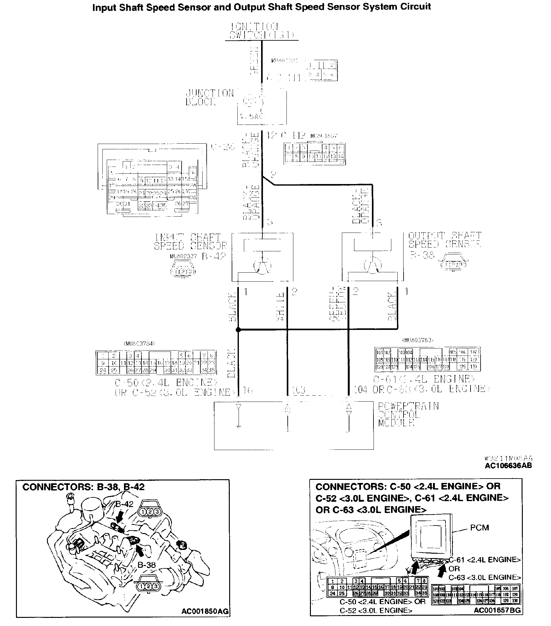
DTC 44: 4th Gear Incorrect Ratio
CIRCUIT OPERATION
- A coil built into the input shaft speed sensor generates pulse signal of 0 (-> 5 volts at both ends of this coil when the input shaft rotates. The pulse signal frequency increases with the rise in input shaft speed.
- Both ends of the coil are connected to the PCM (terminals 16 and 103) via the input shaft speed sensor connector (terminals 1 and 2).
- The PCM detects the input shaft speed with the signal input to terminal (terminal 103).
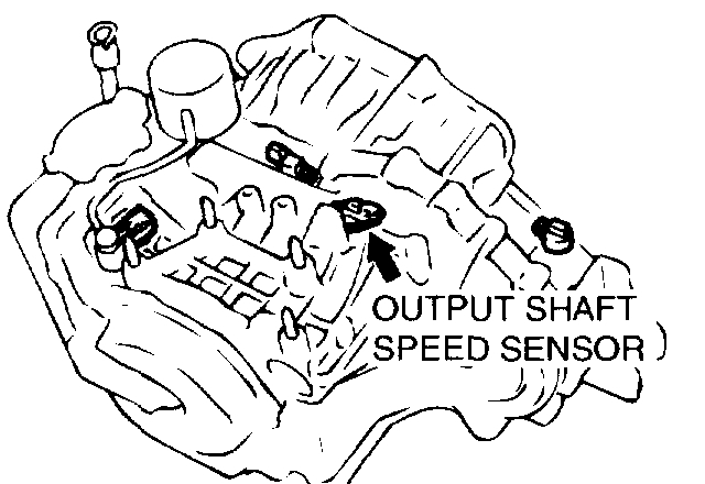
- A coil built into the output shaft speed sensor generates pulse signal of 0 (-> 5 volts at both ends of this coil when the output shaft rotates. The pulse signal frequency increases with the rise in output shaft speed.
- Both ends of the coil are connected to the PCM (terminals 16 and 104) via the output shaft speed sensor connector (terminals 1 and 2).
- The PCM detects the output shaft speed with the signal input to terminal (terminal 104).
TROUBLESHOOTING HINTS (The most likely causes for this code to be set:)
- Malfunction of the input shaft speed sensor
- Malfunction of the output shaft speed sensor
- Malfunction of the PCM
- Malfunction of the underdrive clutch retainer
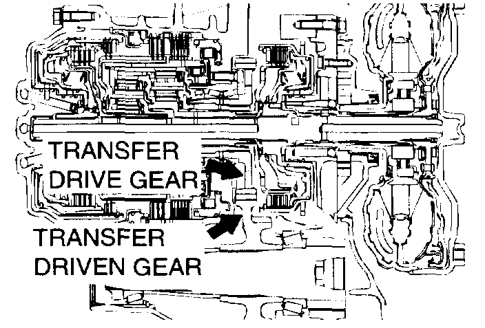
- Malfunction of the transfer drive gear or driven gear
- Malfunction of the low-reverse brake system (for code number"41," "46")
- Malfunction of the underdrive clutch system (for code number"41," "42,""43")
- Malfunction of the second brake system (for code number "42," "44")
- Malfunction of the overdrive clutch system (for code number"43," "44")
- Malfunction of the reverse clutch system (for code number"46")
- Noise generated
DIAGNOSIS
Required Special Tool:
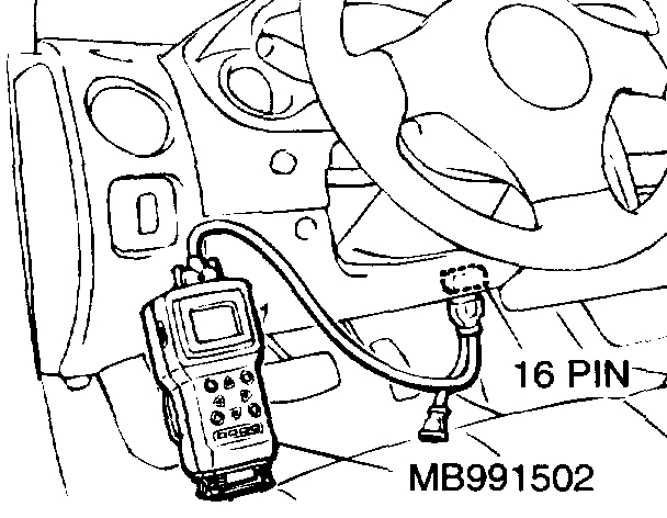
- MB991502: Scan Tool (MUT-II)
STEP 1. Using scan tool MB991502, check the A/T diagnostic trouble code.
CAUTION: To prevent damage to scan tool MB991502, always turn the ignition switch to the "LOCK" (OFF) position before connecting or disconnecting scan tool MB991502.
pic 3
1) Connect scan tool MB991502 to the data link connector.
2) Turn the ignition switch to the "ON" position.
3) Read the A/T diagnostic trouble code.
4) Turn the ignition switch to the "LOCK" (OFF) position.
Q: Is A/T diagnostic trouble code numbers "22" or "23" output?
YES: Refer to code number 22: Input Shaft Speed Sensor System, or refer to code number 23: Output Shaft Speed Sensor System.
NO: Go to Step 2.
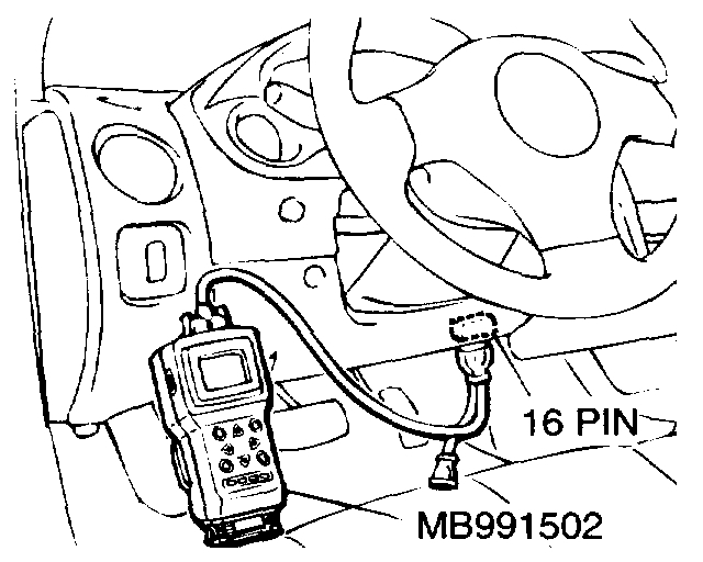
STEP 2. Using scan tool MB991502, carry out the actuator test.
pic 4
1) Connect scan tool MB991502 to the data link connector.
2) Turn the ignition switch to the "ON" position.
3) Set scan tool MB991502 to actuator test mode for following items.
a. item 01: Low-reverse Solenoid Valve
b. item 02: Underdrive Solenoid Valve
c. item 03: Second Solenoid Valve
d. item 04: Overdrive Solenoid Valve
- An operation sound should be heard from solenoid valve when solenoid valve is operated.
4) Turn the ignition switch to the "LOCK" (OFF) position.
Q: Is the solenoid valve operating properly?
YES: Go to Step 3.
NO: Replace the corresponding solenoid valve.
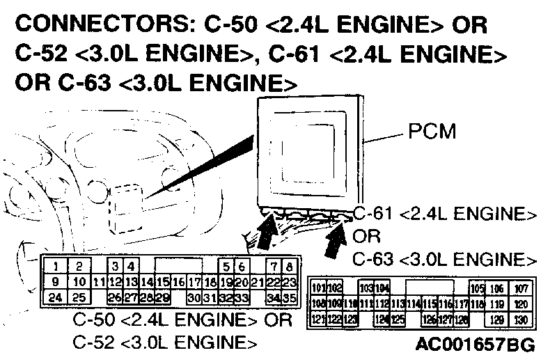
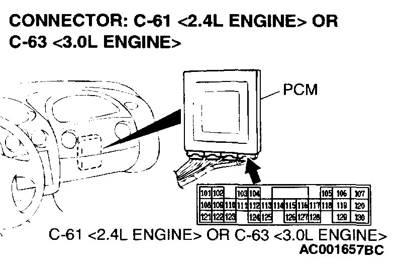
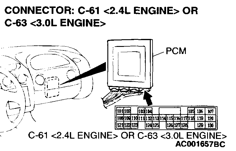
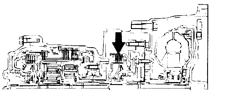
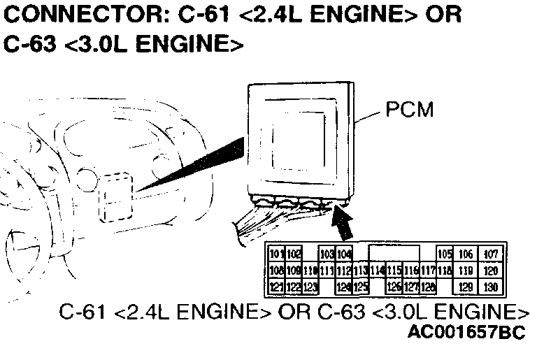
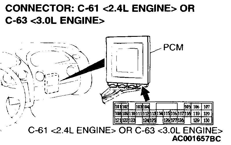
STEP 3. Using the oscilloscope, check the waveform at PCM connectors C-50 (2.4L Engine> or C-52 (3.0L Engine> and C-61 (2.4L Engine> or C-63 (3.0L Engine> by backprobing.
pic 5
1) Do not disconnect connectors C-50 (2.4L Engine> or C-52 (3.0L Engine> and C-61 (2.4L engine> or C-63 (3.0L Engine>.
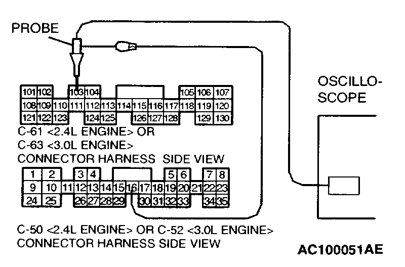
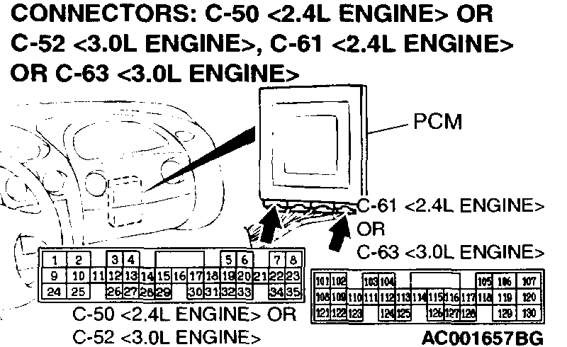
pic 6
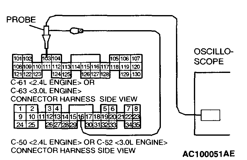
2) Connect an oscilloscope probe to PCM connector C-50 (2.4L Engine> or C-52 (3.0L Engine> terminal 16 and to PCM connector C-61 (2.4L engine> or C-63 (3.0L Engine> terminal 103 by backprobing.
3) Start the engine and run at constant speed of 50km/h (31 mph). (Gear range: 3rd gear)
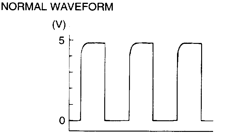
pic 7
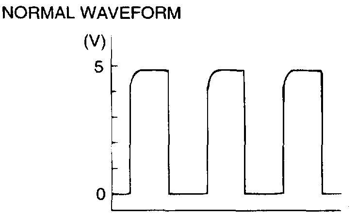
4) Check the waveform.
- The waveform should show a pattern similar to the illustration. The maximum value should be 4.8 volts and more and the minimum value 0.8 volts and less. The output waveform should not contain electrical noise.
5) Turn the ignition switch to the "LOCK" (OFF) position.
Q: Is the waveform normal?
YES: Go to Step 8.
NO: Go to Step 4.
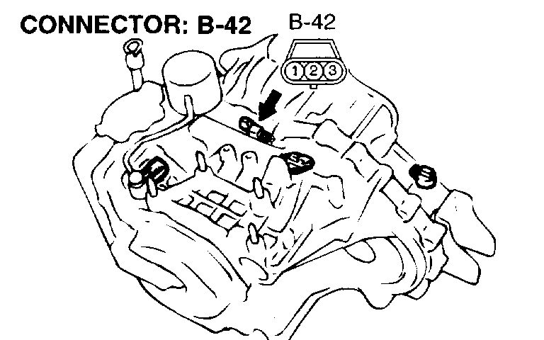
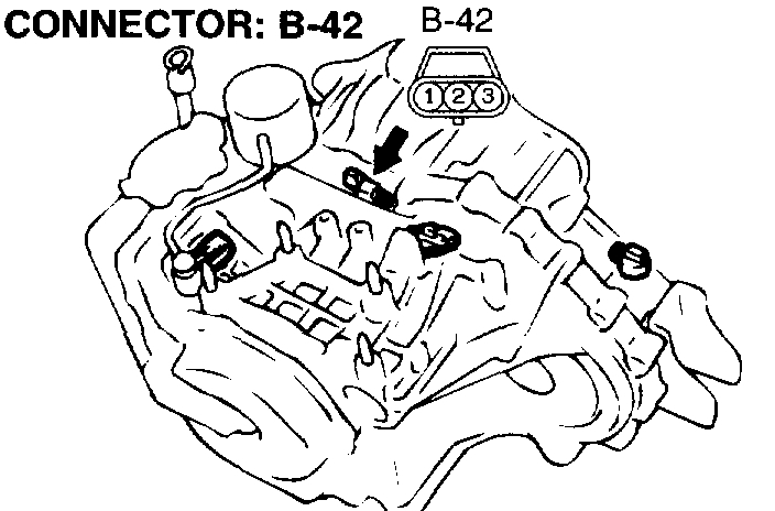
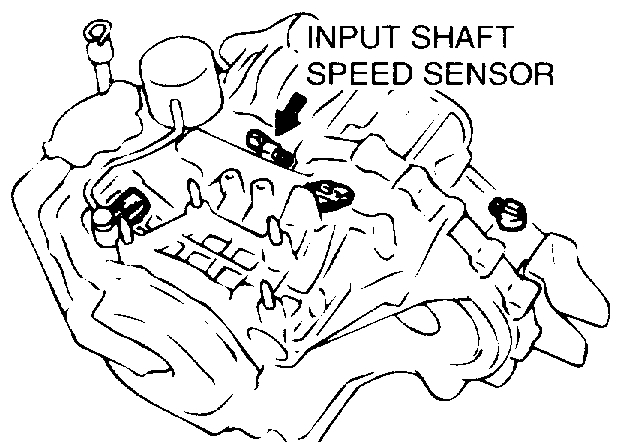
STEP 4. Check connectors B-42 at input shaft speed sensor and C-61 (2.4L Engine> or C-63 (3.0L Engine> at PCM for damage.
pic 8
pic 9
Q: Are the connectors in good condition?
YES: Go to Step5.
NO: Repair or replace the defective connector(s).
STEP 5. Check harness for damage between input shaft speed sensor connector B-42 terminal 2 and PCM connector C-61 (2.4L Engine> or C-63 (3.0L Engine> terminal 103.
pic 10
pic 11
Q: Is the harness wire in good condition?
YES: Go to Step 6.
NO: Repair it.
STEP 6. Replace the input shaft speed sensor.
pic 12
1) Replace the input shaft speed sensor.
2) Test drive the vehicle.
3) Check for A/T diagnostic trouble code.
Q: Is the A/T diagnostic trouble code output?
YES: Go to Step 7.
NO: The inspection is complete.
STEP 7. Replace the underdrive clutch retainer.
pic 13
1) Replace the underdrive clutch retainer.
2) Test drive the vehicle.
3) Check for A/T diagnostic trouble code.
Q: Is the A/T diagnostic trouble code output?
YES: The A/T diagnostic trouble code may have set due to external Radio Frequency (RFI), possibly caused by cellular phone activity, after market components installed on the vehicle, etc.
NO: The inspection is complete.
STEP 8. Using the oscilloscope, check the waveform at PCM connectors C-50 (2.4L Engine> or C-52 (3.0L Engine> and C-61 (2.4L Engine> or C-63 (3.0L Engine> by backprobing.
pic 14
1) Do not disconnect connectors C-50 (2.4L Engine> or C-52 (3.0L Engine> and C-61 (2.4L engine> or C-63 (3.0L Engine>.
pic 15
2) Connect an oscilloscope probe to PCM connector C-50 (2.4L Engine> or C-52 (3.0L Engine> terminal 16 and to PCM connector C-61 (2.4L engine> or C-63 (3.0L Engine> terminal 104 by backprobing.
3) Start the engine and run at constant speed of 50 km/h (31 mph). (Gear range: 3rd gear)
pic 16
4) Check the waveform.
- The waveform should show a pattern similar to the illustration. The maximum value should be 4.8 volts and more and the minimum value 0.8 volts and less. The output waveform should not contain electrical noise.
5) Turn the ignition switch to the "LOCK" (OFF) position.
Q: Is the waveform normal?
YES: Go to Step 13.
NO: Go to Step 9.
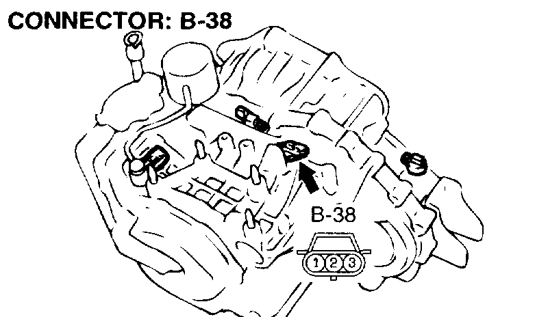
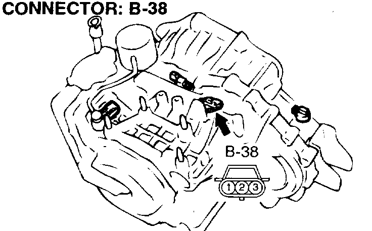
STEP 9. Check connectors B-38 at output shaft speed sensor and C-61 (2.4L Engine> or C-63 (3.0L Engine> at PCM for damage.
pic 17
pic 18
Q: Are the connectors in good condition?
YES: Go to Step 10.
NO: Repair or replace the defective connector(s).
STEP 10. Check harness for damage between output shaft speed sensor connector B-38 terminal 2 and PCM connector C-61 (2.4L Engines or C-63 (3.0L Engines terminal 104.
pic 19
pic 20
Q: Is the harness wire in good condition?
YES: Go to Step 11.
NO: Repair it.
STEP 11. Replace the output shaft speed sensor.
pic 21
1) Replace the output shaft speed sensor.
2) Test drive the vehicle.
3) Check for A/T Diagnostic Trouble Code (DTC).
Q: Is the A/T diagnostic trouble code output?
YES: Go to Step 12.
NO: The inspection is complete.
STEP 12. Replace the transfer drive gear or driven gear.
pic 22
1) Replace the transfer drive gear or driven gear.
2) Test drive the vehicle.
3) Check for A/T diagnostic trouble code.
Q: Is the A/T diagnostic trouble code output?
YES: The A/T diagnostic trouble code may have set due to external Radio Frequency (RFI), possibly caused by cellular phone activity, after market components installed on the vehicle, etc.
NO: The inspection is complete.
STEP 13. Replace the PCM.
1) Replace the PCM.
2) Test drive the vehicle.
3) Check for A/T diagnostic trouble code.
Q: Is the A/T diagnostic trouble code output?
YES: Go to Step14.
NO: The inspection is complete.
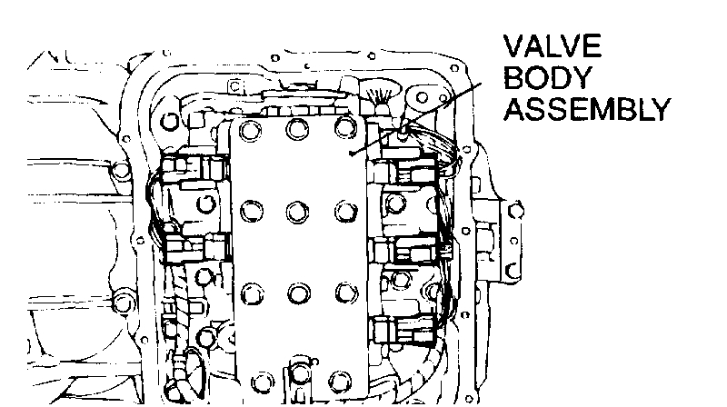
STEP 14. Replace the valve body.
pic 24
1) Replace the valve body.
2) Test drive the vehicle.
3) Check for A/T diagnostic trouble code.
Q: Is the A/T diagnostic trouble code output?
YES: Go to Step 15.
NO: The inspection is complete.
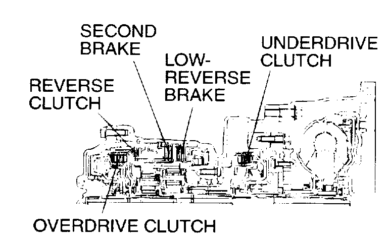
STEP 15. Overhaul the A/T.
pic 25
1) Replace the following parts.
- If DTC No.41, No.42, No.43 are output individually or in a group, replace the underdrive clutch.
- If DTC No.43, No.44 are output individually or in a group, replace the overdrive clutch.
- If DTC No.46 is output, replace the reverse clutch.
- If DTC No.41, No.46 are output individually or in a group, replace the low-reverse brake.
- If DTC No.42, No.44 are output individually or in a group, replace the second brake.
- If DTC No.41 is output, replace the One-Way Clutch (OWCL).
2) Test drive the vehicle.
3) Check for A/T diagnostic trouble code.
Q: Is the A/T diagnostic trouble code output again?
YES: The A/T diagnostic trouble code may have set due to external Radio Frequency (RFI), possibly caused by cellular phone activity, after market components installed on the vehicle, etc.
NO: The inspection is complete.
__________________________________
I hope this helps. Let me know if you have other questions
Take care,
Joe
Images (Click to enlarge)
Oct 15, 2020 at 5:59 PM