hi,
the code indicates an issue with the transmission (cvt) and the acceleration sensor circuit. i realize you did scan the computer, but in this case, you should scan the entire can bus system. can stands for computer area network. i have a feeling that is where the problem will be found. here is a video showing how this is done:
https://youtu.be/inilnsjovfa
now, i do have the diagnostics for the code. i will include them here.
2016 toyota corolla l4-1.8l (2zr-fae)
k313 continuously variable transaxle system (cvt) [08/2013 - 08/2016]
vehicle all diagnostic trouble codes ( dtc ) testing and inspection p code charts p1585 k313 continuously variable transaxle system (cvt) [08/2013 - 08/2016]
p1585; acceleration sensor circuit; 2014 - 2016 my corolla [08/2013 - 08/2016]
dtc p1585 acceleration sensor circuit
description
the ecm determines the vehicle inclination based on a signal from the airbag sensor assembly (yaw rate and acceleration sensor). if a malfunction in the airbag sensor assembly (yaw rate and acceleration sensor) is determined based on a malfunction signal from the brake actuator assembly (skid control ecu), the ecm cancels neutral control as a fail-safe function.
hint: the airbag sensor assembly (yaw rate and acceleration sensor) signal is sent to the brake actuator assembly (skid control ecu) via can communication.
if can communication dtcs are output, perform troubleshooting for those dtcs first.
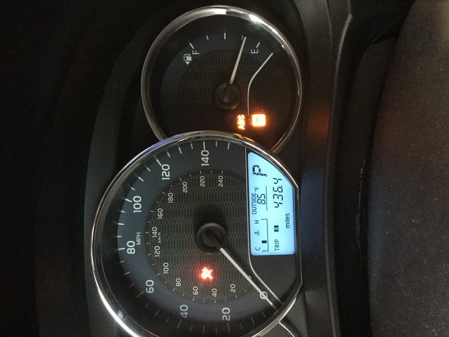
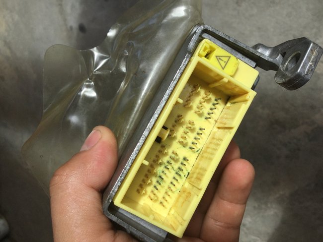
see pic 1 and 2. i overlapped them so you could follow the procedure.
wiring diagram
caution / notice / hint
notice:
perform the universal trip to clear permanent dtcs.
click here k313 (cvt): continuously variable transaxle system: dtc check / clear
procedure
1. check dtc output
connect the techstream to the dlc3.
turn the ignition switch to on.
turn the techstream on.
check for dtcs.
powertrain / engine and ect / trouble codes
result:
b -- go to can communication system networking: can communication system(w/o central gateway ecu / diagnosis system / networking: can communication system(w/o central gateway ecu) diagnosis system networking: can communication system (w/o central gateway ecu) diagnosis system
2. read value using techstream (g sensor)
connect the techstream to the dlc3.
turn the ignition switch to on.
turn the techstream on.
enter the following menus: powertrain / engine and ect / data list / primary.
in accordance with the display on the techstream, read the data list.
powertrain / engine and ect / data list
tester display
g sensor
3. replace airbag sensor assembly
replace the airbag sensor assembly (yaw rate and acceleration sensor).
click here [ supplemental restraint systems: center airbag sensor assembly: components ]
result: proceed to next
4. perform initialization
notice:
performing reset memory will clear the learned value of the yaw rate and acceleration sensor (deceleration sensor zero point calibration) and the cvt oil pressure (cvt oil pressure calibration). make sure to perform reset memory, yaw rate and acceleration sensor zero point calibration, and cvt oil pressure calibration when replacing any of the parts shown in the following table:
after performing reset memory, always perform yaw rate and acceleration sensor (deceleration sensor zero point) calibration first, and then cvt oil pressure calibration.
always perform calibration with the vehicle on level ground.
do not shake or vibrate the vehicle during calibration.
using the techstream, perform reset memory, deceleration sensor zero point calibration and cvt oil pressure calibration.
click here [ k313 (cvt): continuously variable transaxle system: initialization ]
check for dtcs again.
click here [ k313 (cvt): continuously variable transaxle system: dtc check / clear ]
result:
check out the diagrams (below). let us know what happens and please upload pictures or videos of the problem.
Images (Click to enlarge)
Aug 30, 2020 at 8:41 PM