Transmission is stuck in limp mode

Tiny
DODGEPODGE
  • MEMBER
  • 1994 DODGE GRAND CARAVAN
  • 3.3L
  • V6
  • 2WD
  • AUTOMATIC
  • 190,000 MILES
I disconnected the harness to the tcm to replace a heater hose. And when I was finished I replaced the harness to the tcm. And the trans wont go through the gears. The speedometer wont work either and the check engine light is on. So i'm throwing codes. But my snanner wont work right now either DOH ! It was shifting fine before I did anything. So what should I be looking at? Fix one thing and something else goes wrong. Thanks
Monday, May 6th, 2024 AT 9:33 AM

23 Replies

Tiny
KEN L
  • MASTER CERTIFIED MECHANIC
  • 43,356 POSTS
The key is the speedometer is not working, I would check the VSS wiring connector, also clear the codes by disconnecting the battery for 5 minutes. Here is the sensor location so you can check it out, also double check the wiring connector at the TCM, you could have a pin that is rolled over or corroded. Also, this is a OBD1 car so this guide can help you get any codes,

https://www.2carpros.com/articles/retrieve-trouble-codes-for-chrysler-dodge-plymouth-odb1-1995-and-earlier-car-mini-van-and-light-trucks

Also called an output speed sensor. Check out the images (below). Let us know how it goes
Was this
answer
helpful?
Yes
No
Monday, May 6th, 2024 AT 8:22 PM
Tiny
JACOBANDNICKOLAS
  • MECHANIC
  • 108,388 POSTS
Hi:

Was the battery disconnected prior to disconnecting and reconnecting the TCM? If it wasn't, that can cause power spikes to the module and damage it.

Also, try this procedure to see if there are any codes stored.

https://www.2carpros.com/articles/retrieve-trouble-codes-for-chrysler-dodge-plymouth-odb1-1995-and-earlier-car-mini-van-and-light-trucks

let me know what you find

Joe
Was this
answer
helpful?
Yes
No
Monday, May 6th, 2024 AT 8:24 PM
Tiny
DODGEPODGE
  • MEMBER
  • 88 POSTS
Hi ken what are u referring to vss? I took off the tcm connector again and checked everything looks ok. Pins are nice and shiny. So can the speed sensors be checked with an ohm meter still installed? How can I get specs for them? Will they both be the same? Thanks
Was this
answer
helpful?
Yes
No
Tuesday, May 7th, 2024 AT 7:30 AM
Tiny
DODGEPODGE
  • MEMBER
  • 88 POSTS
Hi jacob yes I did remove the battery cable before I took off the tcm connector. Luckily I remembered that from the last time I had encountered this problem. I got my scanner working again yesterday and the only code I pulled was a code 27 I pulled off the connector to the #5 injector accidentally and put it back on. But no other ones. So right now i'm confused. I guess I can try it again? Thanks
Was this
answer
helpful?
Yes
No
Tuesday, May 7th, 2024 AT 7:38 AM
Tiny
DODGEPODGE
  • MEMBER
  • 88 POSTS
I used my scanner again and all I got was a dtc 21 so?
Was this
answer
helpful?
Yes
No
Tuesday, May 7th, 2024 AT 1:24 PM
Tiny
JACOBANDNICKOLAS
  • MECHANIC
  • 108,388 POSTS
Hi:

Code 21 is related to the OD pressure switch circuit. I attached the diagnostics below specific to that code. The code indicates the OD switch is either closed or open when it shouldn't be.

Take a look through the diagnostics and let me know if you are comfortable performing them. Also, let me know what you find.

Take care,

Joe

See pic below
Was this
answer
helpful?
Yes
No
Tuesday, May 7th, 2024 AT 6:58 PM
Tiny
DODGEPODGE
  • MEMBER
  • 88 POSTS
Hi joe the code 21 was done with my engine scanner. I dont have a trans scanner. So how can I figure out my speedo dont work? Wouldnt that give a dtc on my engine scanner? I asked for specs for the input and output speed sensors first rather than replacing them thanks
Was this
answer
helpful?
Yes
No
Wednesday, May 8th, 2024 AT 8:11 AM
Tiny
JACOBANDNICKOLAS
  • MECHANIC
  • 108,388 POSTS
When I look for the code in my manual, the engine doesn't show up. Other things do including the transmission and the cruise control. (See pic 1)

Also, I attached the diagnostics for testing both the input and output speed sensors. Take a look and let me know if it helps.

Joe

See pics below
Was this
answer
helpful?
Yes
No
Wednesday, May 8th, 2024 AT 6:39 PM
Tiny
DODGEPODGE
  • MEMBER
  • 88 POSTS
Well joe I encountered something strange? I see 3 sensors on my transmission 1is over the shift solenoid then there is 1 to the right of the shift solenoid then there is another to the right of that some more I pulled the harness off the one to the right of the shift solenoid and theres 3 pins in the sensor so I dont know which pins i'm supposed to use when I test for resistance? Hense i'm puzzled. So
Was this
answer
helpful?
Yes
No
Thursday, May 9th, 2024 AT 2:45 PM
Tiny
JACOBANDNICKOLAS
  • MECHANIC
  • 108,388 POSTS
Hi:

I attached a picture below showing the input and output speed sensor locations. Are these the ones you are referring to?

Let me know.

Joe

See pic below
Was this
answer
helpful?
Yes
No
Thursday, May 9th, 2024 AT 7:47 PM
Tiny
DODGEPODGE
  • MEMBER
  • 88 POSTS
Looks to be right. I guess that was the transmission range switch I pulled off with the 3 prongs. I'll try the other ones and see how many they have and try to test them? Would either of them cause no speedometer? Thanks
Was this
answer
helpful?
Yes
No
Friday, May 10th, 2024 AT 1:31 PM
Tiny
JACOBANDNICKOLAS
  • MECHANIC
  • 108,388 POSTS
Hi:

That is very possible. As far as the speedometer, the Transaxle Control Module (TCM) calculates vehicle speed based on the input received from both the Input and Output speed sensor mounted on the transaxle. The output sensor is the most likely suspect.

I hope this helps.

Take care,

Joe
Was this
answer
helpful?
Yes
No
Friday, May 10th, 2024 AT 7:42 PM
Tiny
DODGEPODGE
  • MEMBER
  • 88 POSTS
I tried to test the output speed sensor and the area is just to tight I couldnt really hold the test probes together to try to get a reading. And I didnt have the right size socket to remove it. I'm gonna try to test the resistance at the tcm and see if I get a reading? Do you know if the sensors are the same for the 41te and the 41ae trans? Thanks
Was this
answer
helpful?
Yes
No
Saturday, May 11th, 2024 AT 2:06 PM
Tiny
JACOBANDNICKOLAS
  • MECHANIC
  • 108,388 POSTS
Hi:

If I was to check resistance, I would do it right at the sensor. The wiring itself will add to your reading.

Also, based on my manual, it is the same sensor.

Let me know what you find.

Joe
Was this
answer
helpful?
Yes
No
Saturday, May 11th, 2024 AT 7:43 PM
Tiny
CARADIODOC
  • MECHANIC
  • 33,763 POSTS
Hi guys. If I could stick my nose in here for a moment, testing speed sensor is pointless. They do not measure a resistance like a throttle position sensor or temperature sensor. Two-wire speed sensors, including wheel speed sensors for anti-lock brakes generate an AC signal voltage with the frequency proportional to speed. As with all voltages generated this way, speed is an important part of the strength, or voltage of the signal, but that voltage doesn't matter, as long as it's high enough that the computer can read it. Then, it's the frequency it cares about, not the voltage.

Three-wire speed sensors generate the AC signal voltage the same way, but then there's additional circuitry that puts out a very nice clean square wave. With their very definite rise and fall times, the timing of those signals is very precise. That's not important for speed signals, but it is for position sensors like the crankshaft position sensor and the camshaft position sensor.

To test a speed sensor, you need to connect an oscilloscope such as is used in tv repair, and you must be able to run the vehicle in gear. There's a much easier and less complicated way. That is to simply use a scanner to view live data, and see what it shows for the engine speed, road speed, or wheel speed. If the computer can read it, the sensor is working.

I've been following along to learn the solution. That's why I noticed too much time is being spent on trying to do a test that can't be done.

By the way, a lot of competent do-it-yourselfers also figure out they need to read these signals with a digital voltmeter set on AC Volts. That won't work either except to tell you if there's something vs. Nothing. Digital meters are designed to read 60 hertz voltages as found in house wiring. Some expensive meters will be accurate up to 400 hertz for military use. The front tone ring on a mid '90s Caravan brake rotor has 57 teeth so the sensor will generate 57 hertz when the wheel is spinning at one revolution per second. Since speed is a factor in signal strength, the signal voltage is very low at that speed, and will likely be too low to be read by the computer. That, in part, is why all ABS systems deactivate below 9 or 15 mph. At faster rotational speeds, the signal voltage will increase, but the meter loses its response, and will likely show a lower voltage.

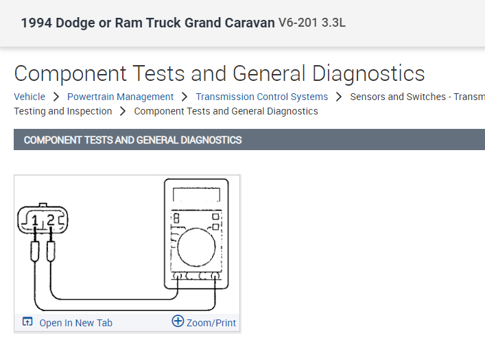
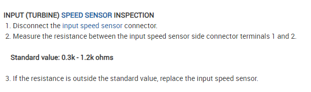
I should correct myself too in that you CAN measure the resistance of a two-wire speed sensor as it is just a long piece of wire wrapped around a magnet. It's extremely rare to have one read the wrong resistance value, so it isn't really necessary to know the specs. Those specs are provided in service manuals, but only for reference, and for training purposes. You're looking for infinite resistance, meaning an open circuit, to show if one end of the wire is broken off its terminal internally. If you find anything other than an open circuit, the wire is okay. Common or typical values range from 100 ohms to as much as 750 ohms, (that I have memorized), for the distributor pickup on my '78 LeBaron. You can't get to that coil of wire to measure its resistance in a three-wire sensor. The only thing you can do with those is live testing by running something to make the sensor generate its signal.

While not real common, a speed sensor can fail intermittently and work at other times, depending on temperature, vibration, or flexing wires like with ABS wheel speed sensors. A more common source of intermittent dropouts of the signal on some sensor designs is too large of an air gap. For most designs, that is set by the design of the mounting bracket, but there have been some that need special procedures to set that air gap.

Hope that helps you move ahead to solve any remaining problems.
Was this
answer
helpful?
Yes
No
Saturday, May 11th, 2024 AT 8:18 PM
Tiny
CARADIODOC
  • MECHANIC
  • 33,763 POSTS
Update: I actually have five Grand Caravans, including a '94 and a '95, but my memory has faded a bit. I just looked at the diagrams and I think I see what might be causing some confusion. Both the output speed sensor on the transmission, and the camshaft position sensor on the engine are drawn exactly like a throttle position sensor, which incorrectly implies they can be measured with an ohm meter. Maybe the speed sensor can, as it's a two-wire sensor, but the camshaft position sensor definitely can not be measured the way the drawing implies.

My '88 model uses a speedometer cable, (which is one reason why I've been searching for a nice rust-free one to replace mine), and it needs no complicated computer to run the speedometer. It does have a two-wire speed sensor at the transmission, but that is only for the cruise control and for the transmission's lock-up torque converter. My '89 model uses a speed sensor only, along with a computer to run the speedometer. As I recall, that is a three-wire sensor, so it can't be measured.
Was this
answer
helpful?
Yes
No
Saturday, May 11th, 2024 AT 8:40 PM
Tiny
DODGEPODGE
  • MEMBER
  • 88 POSTS
Thanks cardiodoc for the input but now i'm even more confused. I thought I was making some headway but? I cant get my probes on the output speed sensor as its too tight there. So I traced the wires back to the tcm and got a reading. There is continuity. Both the input and speed sensors read about the same. I got a.536 on the output sensor and a.558 on the input sensor. I used my digital v.O.M as I cant find my analog v.O.M I get confused with the digital one. I was using the 2k scale so does that mean I move the decimal 3 spaces to the right? I think the main thing is the speedo isnt working? This should be simple? Should I swear more? Thanks
Was this
answer
helpful?
Yes
No
Sunday, May 12th, 2024 AT 1:11 PM
Tiny
KEN L
  • MASTER CERTIFIED MECHANIC
  • 43,356 POSTS
Yes, the speedometer not working is the problem. Can you remove the output shaft speed sensor and use a flashlight to see if the reluctor wheel is in sight? Also, sensors can test good but still be bad. How were the pins of the connectors to the TCM?
Was this
answer
helpful?
Yes
No
Monday, May 13th, 2024 AT 9:47 AM
Tiny
DODGEPODGE
  • MEMBER
  • 88 POSTS
Well i'll have to try to find another socket. My socket kept slipping off. As far as seeing in there I doubt that there isnt enough room to get an eyeball up in there. What would I be looking for though? And as far as the pins? They almost look as new. The thing thats baffling though is? Just disconnecting the tcm wire bundle and reconnecting it? And yes again the battery was disconnected first. Thanks
Was this
answer
helpful?
Yes
No
Monday, May 13th, 2024 AT 11:38 AM
Tiny
KEN L
  • MASTER CERTIFIED MECHANIC
  • 43,356 POSTS
Is the connector back together firmly did you hear a "click" when reconnecting it? It sounds like the TCM has gone bad, Lets remove the battery cable on the negative side for 5 minutes and reconnect it to see if that changes anything?
Was this
answer
helpful?
Yes
No
Tuesday, May 14th, 2024 AT 9:50 AM

Please login or register to post a reply.

Sponsored links