TPS not responding to reset

Tiny
CHRIS SMART
  • MEMBER
  • 2003 INFINITI G35
  • 3.5L
  • 6 CYL
  • 4WD
  • AUTOMATIC
  • 60,000 MILES
The car has been disturbing me for some time now.
When I depressed the throttle pedal the rpm will not go pass 1,200 to 1,400 rpm's. I have tried all the TPS resetting instructions I saw online and none worked for me.
In my case the check light will not even blink or the throttle body open and close.
Nothing just works. But when I clear the codes, everything will work normal but if I turn off the engine and try to start the car again it will go back to zero.
I have changed the ECM, and the throttle body still the same thing.
These are the trouble codes I get each time I scan it :
1) u1000
2) p1754
3) p1764
4) p1705
5) p0550
6) p1564
7) p0013
8) p0051
9)p0011
10) p0021
Codes number 1-4 are from TA check light scanning.
Wednesday, November 7th, 2018 AT 1:13 AM

10 Replies

Tiny
ASEMASTER6371
  • MECHANIC
  • 52,797 POSTS
Good morning.

This is going to take a while.

I will address the codes.

This is most likely way beyond a normal tech and requires factory scan tool to monitor.

U1000

Description
CAN (Controller Area Network) is a serial communication line for real time application. It is an on-vehicle multiplex communication line with high data communication speed and excellent error detection ability. Many electronic control units are equipped onto a vehicle and each control unit shares information and links with other control units during operation (not independent). In CAN communication control units are connected with 2 communication lines (CAN H line CAN L line) allowing a high rate of information transmission with less wiring. Each control unit transmits/receives data but selectively reads required data only.

1754

P1754
Descriptor
Probable Causes
Automatic Transmission Fluid Pressure Switch 3
Input Clutch Solenoid Valve

1764

P1764
Descriptor
Probable Causes
Automatic Transmission Fluid Pressure Switch 5
Direct Clutch Solenoid Valve

1705

DTC P1705 THROTTLE POSITION SENSOR

Description
Electric throttle control actuator consists of throttle control motor, accelerator pedal position sensor, throttle position sensor, etc. The actuator sends a signal to the ECM, and ECM sends signals to TCM with CAN communication.

On Board Diagnosis Logic
- This is an OBD-II self-diagnostic item.
- Diagnostic trouble code "TP SEN/CIRC A/T" with CONSULT-II or P1705 without CONSULT-II is detected when TCM does not receive the proper accelerator pedal position signals (input by CAN communication) from ECM.

Possible Cause
Harness or connectors (The sensor circuit is open or shorted.)

DTC Confirmation Procedure

NOTE: If "DTC Confirmation Procedure" has been previously conducted, always turn ignition switch "OFF" and wait at least 10 seconds before conducting the next test.

After the repair, perform the following procedure to confirm the malfunction is eliminated.
Was this
answer
helpful?
Yes
No
Wednesday, November 7th, 2018 AT 3:07 AM
Tiny
ASEMASTER6371
  • MECHANIC
  • 52,797 POSTS
More information.

550

P0550
Descriptor
Probable Causes
Power Steering Pressure Sensor

1564

P1564
Descriptor
Probable Causes
Automatic Speed Control Device (ASCD) Steering Switch
Engine Control Module (ECM)

13, not listed in code list

51

P0051
Descriptor
Probable Causes
Air Fuel Ratio (A/F) Sensor 1 Heater
Air Fuel Ratio (A/F) Sensor 1 Heater Circuit Open or Shorted
Air Fuel Ratio (A/F) Sensor 1 Heater Circuit Shorted

last 2 are together
Was this
answer
helpful?
Yes
No
+1
Wednesday, November 7th, 2018 AT 3:13 AM
Tiny
ASEMASTER6371
  • MECHANIC
  • 52,797 POSTS
Okay, sorry for all the posts but it would not take all the information in one post.

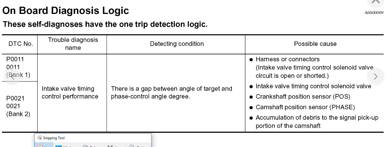
The key here is the transmission codes. That is what is putting you in a limp mode. They need to be addressed first. From the looks of the possibilities, it could be a wiring harness issue or internal.

One thing I would do is check the charging system. Make sure the voltage is between 14 and 14.5 volts. Then switch the range to AC volts. If you show any AC voltage, the alternator is no good. AC voltage will throw many codes because the PCM does not know what to do with a voltage it does not recognize.

Roy

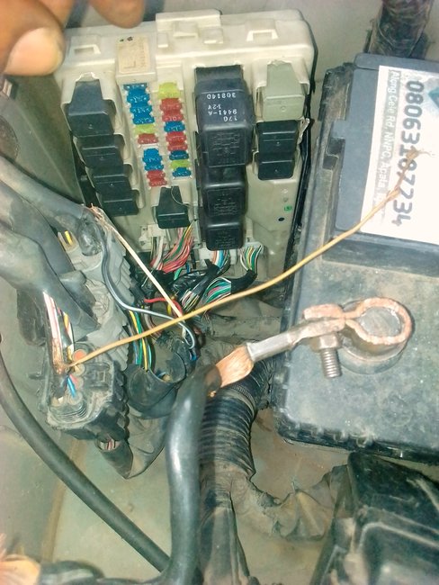
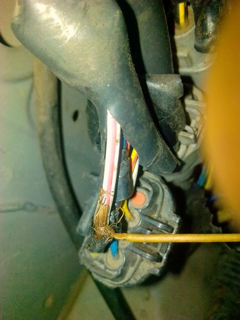
There was a TSB on the 1000 for bad grounds.

Classification:
EC06-002a

Reference:
ITB06-004a

Date:
March 31, 2006

MIL "ON" WITH DTC U1000 OR U101 STORED IN ENGINE CONTROL UNIT

APPLIED VEHICLES:
2002-2004 I35 (CA33)
2002-2006 Q45 (F50)
2004-2006 QX56 (JA60)
2003-2006 FX (S50)
2003-2006 G35 (V35)
2003-2004 M45 (Y34)
2006 M (Y50)

IF YOU CONFIRM

The MIL is "ON" with

DTC U1000 (CAN COMM CIRCUIT) OR

DTC U1010 (CAN COMM) [2006 Models only] stored in the engine control unit,

and

There are no drivability incidents.

DETERMINE IF

This bulletin applies by performing steps 1 and 2 of the Service Procedure.

ACTIONS

If this bulletin applies, there may be excess resistance in certain ground connections:

Clean/re-tighten ECM ground connections.

Clean/re-tighten negative battery cable body connection and battery post connection.

If needed, clean and ensure good contact between the steering member assembly and the left side instrument stay assembly.

IMPORTANT:
The purpose of "ACTIONS" (above) is to give you a quick idea of the work you will be performing. You MUST closely follow the entire Service Procedure as it contains information that is essential to successfully completing the repair.

CLAIMS INFORMATION

imageOpen In New TabZoom/Print

Submit a Primary Part (PP) type claim using the claims coding shown.

SERVICE PROCEDURE:

1. Print the engine Freeze Frame (FF) data using CONSULT-II.

Refer to section EC in the appropriate Service Manual for Freeze Frame diagnostic information.

ImageOpen In New TabZoom/Print

2. Compare your printout to the chart.

A. If your readings match exactly to the readings above go to step 3.

B. If your readings do not match exactly this bulletin does not apply.

Go to section LAN in the appropriate Service Manual for additional diagnostic information.

3. Make sure all ECM ground terminal connections are clean and tight as follows:

imageOpen In New TabZoom/Print

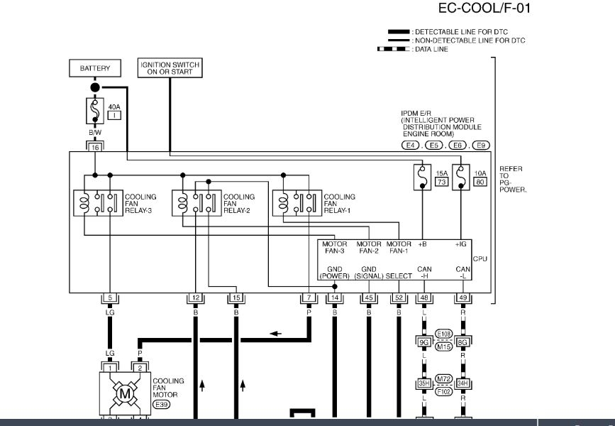
a. Make a list of the ground terminals for your vehicle. Refer to the appropriate Service Manual section EC (Power Supply and Ground Circuits).

ImageOpen In New TabZoom/Print

b. Take your list and go to section PG in the appropriate Service Manual. You'll be able to identify the exact location of the ECM ground terminals you'll need to check.

C. Now go to the ground terminal(s) on the vehicle and remove the nut or bolt that holds the terminal eyelet(s).

D. Clean the following surfaces on each ECM ground terminal. This will ensure good contact in the connections.

Both sides of the eyelet

Eyelet mounting surface

NOTE:
Do not remove paint from painted surfaces in the engine compartment to improve ground. Doing so may cause corrosion/rust.

Nut/bolt threads.

Female threads in bolt holes (use the correct size tap).

E. Reinstall and tighten the nut or bolt that holds the terminal eyelet.

4. If the ECM ground terminals are attached to the steering member assembly (cross brace under the dash):

imageOpen In New TabZoom/Print

a. Remove the fasteners (nuts bolts screws) that attach the left side instrument stay assembly (cross brace support) to the steering member assembly (see Figure 3).

B. Clean the mounting surfaces and fastener threads.

C. Reassemble and tighten the fasteners.

Example only: Steering member support assembly and instrument stay assembly

5. Clean the negative battery cable connection.

A. Write down all the radio presets.

B. Disconnect the negative battery cable at the battery and at the body connection.

C. Clean the following items:

Negative cable-to-body connection eyelet (both sides)

Body connection bolt (head and threads)

Female bolt hole threads (use correct size tap)

NOTE:
Do not remove paint from painted surfaces in the engine compartment to improve ground. Doing so may cause corrosion/rust.

Battery negative post

Negative cable battery terminal

d. Reconnect negative battery cable (at the body and the battery).

E. Reprogram the radio presets.

6. Use CONSULT-II to erase all DTCs.

7. Test drive and re-check for DTCs.

Image

Disclaimer
Was this
answer
helpful?
Yes
No
+1
Wednesday, November 7th, 2018 AT 3:22 AM
Tiny
CHRIS SMART
  • MEMBER
  • 6 POSTS
Thanks for your time and help.
Your answers was helpful.
While I was checking the ECU grounds I divorced that there was a connection form the bunches of wires beside the battery, clipped to the chassis. I do not know what that wire is for but it is an ignition line.
This line was used to feed the cooling fan with ignition current. So what I did was to disconnect the fan from that line and everything was okay.
And I will like to know what that wire is for.
The car works great now even though there are other problems with the car but my main concern was that of throttle body reset and it is working now even without throttle body reset.
Thanks once again and God bless.
Was this
answer
helpful?
Yes
No
Wednesday, November 7th, 2018 AT 2:45 PM
Tiny
ASEMASTER6371
  • MECHANIC
  • 52,797 POSTS
Wow, nice shots. That is a real butcher job.

My concern is why it was done. Do the fans work correctly? That wire was added to bypass something? Make sure everything works as it should. If something does not work, let me know.

Roy
Was this
answer
helpful?
Yes
No
+1
Wednesday, November 7th, 2018 AT 2:49 PM
Tiny
CHRIS SMART
  • MEMBER
  • 6 POSTS
What I noticed was that the fan was replaced with another fan that was not for the And the relay for the fan was powered through this wire.
Was this
answer
helpful?
Yes
No
Wednesday, November 7th, 2018 AT 3:02 PM
Tiny
ASEMASTER6371
  • MECHANIC
  • 52,797 POSTS
I attached a diagram for you to view. Check all three fuses for power on both sides with the key on.

Check the black wire, I believe for power to the relays as it feeds all three.

Roy
Was this
answer
helpful?
Yes
No
Wednesday, November 7th, 2018 AT 3:11 PM
Tiny
CHRIS SMART
  • MEMBER
  • 6 POSTS
Good day sir, I have a problem with Infiniti FX35 smart key
no crank no start from the push and start key switch, but it starts from the kick starter
even without the smart key anywhere close to the car.
Was this
answer
helpful?
Yes
No
Tuesday, November 27th, 2018 AT 7:31 AM
Tiny
ASEMASTER6371
  • MECHANIC
  • 52,797 POSTS
Good morning,

Please start a new question as this is a different vehicle with a different issue.

Go back to the start page and open a new question

Thank you,

Roy
Was this
answer
helpful?
Yes
No
Tuesday, November 27th, 2018 AT 7:37 AM
Tiny
RENEE L
  • ADMIN
  • 1,257 POSTS
Here is the link to post your new question:

https://www.2carpros.com/questions/new

Regards,

Renee
Was this
answer
helpful?
Yes
No
Tuesday, November 27th, 2018 AT 5:37 PM

Please login or register to post a reply.

Sponsored links