Hi,
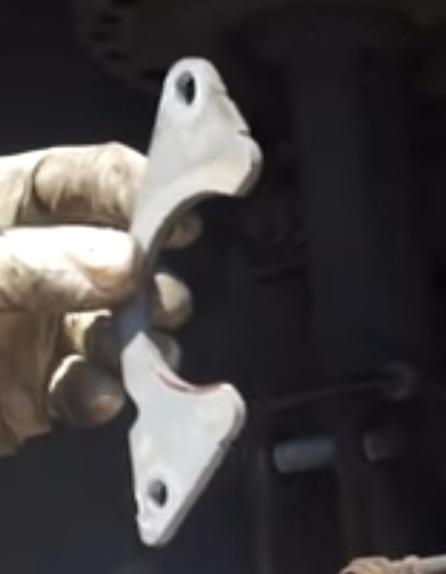
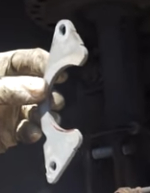
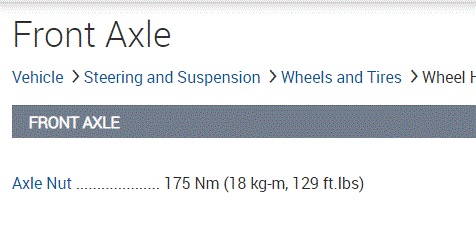
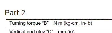
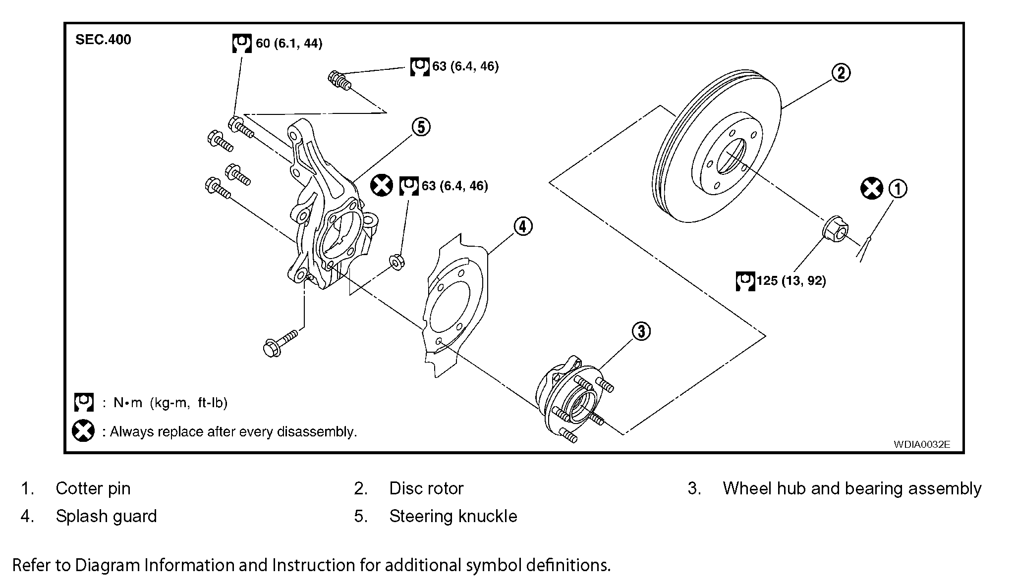
Pics 1 and 2 show the torque specs. Pic 1 is the axle nut and pic 2 is for the ball joints which I believe what you are referring to when you say steering knuckle.
_________________
I don't know if you need it, but here are the directions for replacing the axle. The remaining pictures correlate with the directions.
_____________________________________________
2007 Nissan-Datsun Altima L4-2.5L (QR25DE)
Front Axle
Vehicle Steering and Suspension Steering Front Steering Knuckle Service and Repair Removal and Replacement Front Axle
FRONT AXLE
FRONT WHEEL HUB AND KNUCKLE
Removal and Installation
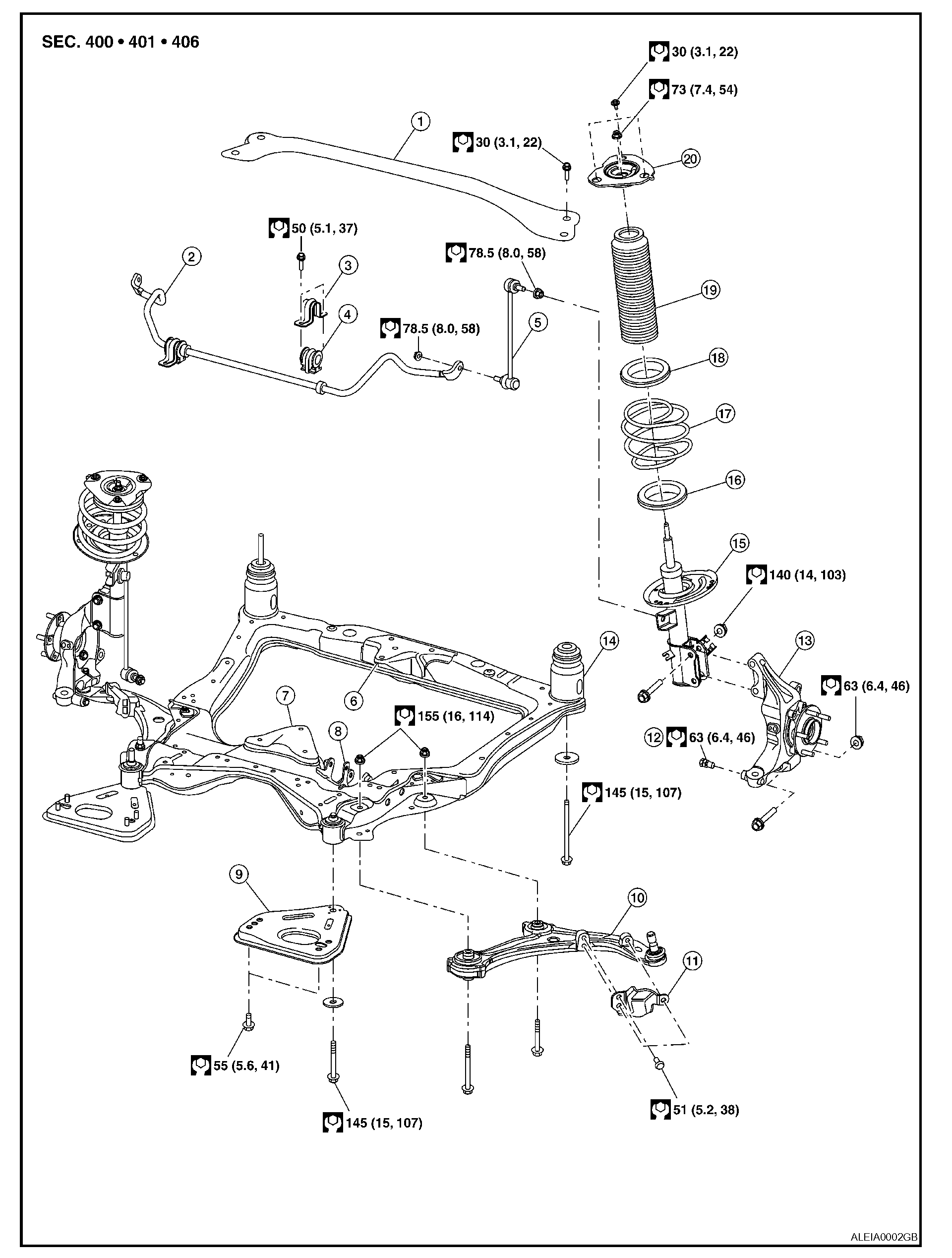
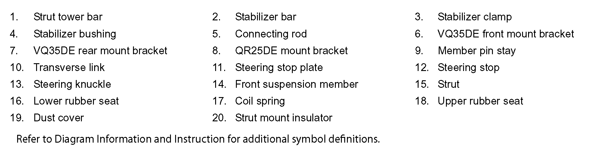
Exploded View FSU-13 (Part 1)
pic 3
Exploded View FSU-13 (Part 2)
pic 4
Exploded View FAX-7
pic 5
REMOVAL
1. Remove wheel and tire from vehicle using power tool.
2. Without disassembling the hydraulic lines, remove brake caliper using power tool. Reposition it aside with wire.
NOTE: Avoid depressing brake pedal while brake caliper is removed.
pic 6
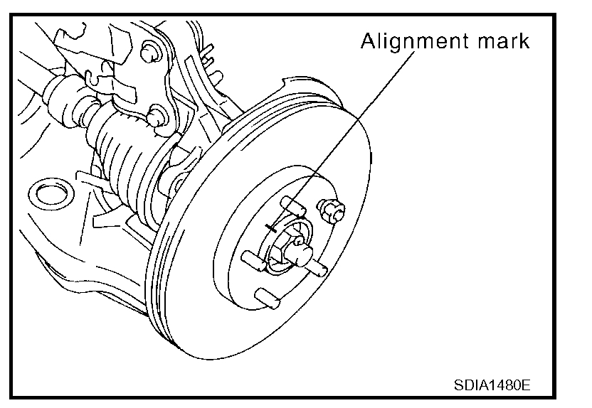
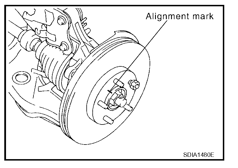
3. Put alignment marks on disc rotor and wheel hub and bearing assembly, then remove disc rotor.
4. Remove wheel sensor from steering knuckle.
CAUTION: Do not pull on wheel sensor harness.
5. Remove cotter pin, then remove lock nut from drive shaft using power tool.
6. Remove steering outer tie-rod cotter pin at steering knuckle, then loosen nut using power tool.
Pic 7
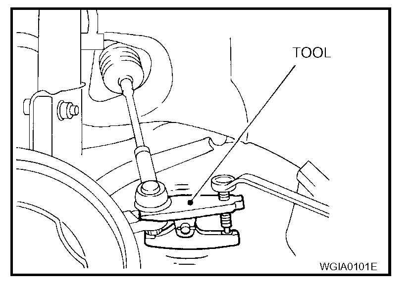
7. Disconnect the outer tie-rod end from steering knuckle using Tool. Be careful not to damage ball joint boot.
CAUTION: To prevent damage to threads and to prevent Tool from coming off suddenly, temporarily tighten mounting nut.
Tool number: HT72520000 (J-25730-A)
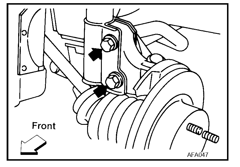
8. Remove transverse link and steering knuckle pinch bolt and nut using power tool. Refer to Exploded View FSU-13.
pic 8
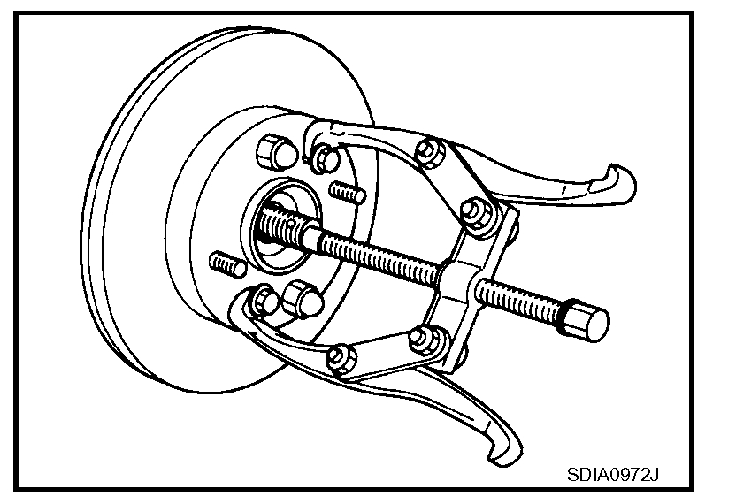
9. Remove wheel hub and bearing assembly from drive shaft using a puller or suitable tool.
CAUTION:
^ When removing wheel hub and bearing assembly, do not apply an excessive angle to drive shaft joint. Also be careful not to excessively extend slide joint.
^ Support drive shaft when removing.
10. Remove wheel hub and bearing assembly bolts using power tool.
11. Remove splash guard and wheel hub and bearing assembly from steering knuckle.
pic 11
12. Remove the lower strut bolts and nuts using power tool. Refer to Exploded View FSU-13.
13. Remove steering knuckle from vehicle.
INSPECTION AFTER REMOVAL
Check for deformity, cracks and damage on each part, replace if necessary.
Ball Joint Inspection
^ Check for boot breakage, axial looseness, and torque of transverse link ball joint and repair as necessary.
INSTALLATION
Installation is in the reverse order of removal. Note the following:
^ Refer to "Removal and Installation" for tightening torques.
CAUTION: Do not reuse non-reusable parts.
pic 12
^ When installing wheel hub and bearing assembly to steering knuckle, align cutout in toner ring cover with wheel sensor mounting hole in steering knuckle.
^ When installing disc rotor on wheel hub and bearing assembly, align the marks. (When not using the alignment mark, refer to BR-6, "DISC ROTOR: Inspection".)
________________________________________
2007 Nissan-Datsun Altima L4-2.5L (QR25DE)
Front Axle
Vehicle Steering and Suspension Steering Front Steering Knuckle Service and Repair Removal and Replacement Front Axle
FRONT AXLE
FRONT WHEEL HUB AND KNUCKLE
Removal and Installation
Exploded View FSU-13 (Part 1)
pic 4
Exploded View FSU-13 (Part 2)
pic 5
pic 6
Exploded View FAX-7
REMOVAL
1. Remove wheel and tire from vehicle using power tool.
2. Without disassembling the hydraulic lines, remove brake caliper using power tool. Reposition it aside with wire.
NOTE: Avoid depressing brake pedal while brake caliper is removed.
pic 7
3. Put alignment marks on disc rotor and wheel hub and bearing assembly, then remove disc rotor.
4. Remove wheel sensor from steering knuckle.
CAUTION: Do not pull on wheel sensor harness.
5. Remove cotter pin, then remove lock nut from drive shaft using power tool.
6. Remove steering outer tie-rod cotter pin at steering knuckle, then loosen nut using power tool.
pic 8
7. Disconnect the outer tie-rod end from steering knuckle using Tool. Be careful not to damage ball joint boot.
CAUTION: To prevent damage to threads and to prevent Tool from coming off suddenly, temporarily tighten mounting nut.
Tool number: HT72520000 (J-25730-A)
8. Remove transverse link and steering knuckle pinch bolt and nut using power tool. Refer to Exploded View FSU-13.
pic 9
9. Remove wheel hub and bearing assembly from drive shaft using a puller or suitable tool.
CAUTION:
^ When removing wheel hub and bearing assembly, do not apply an excessive angle to drive shaft joint. Also be careful not to excessively extend slide joint.
^ Support drive shaft when removing.
10. Remove wheel hub and bearing assembly bolts using power tool.
11. Remove splash guard and wheel hub and bearing assembly from steering knuckle.
pic 10
12. Remove the lower strut bolts and nuts using power tool. Refer to Exploded View FSU-13.
13. Remove steering knuckle from vehicle.
INSPECTION AFTER REMOVAL
Check for deformity, cracks and damage on each part, replace if necessary.
Ball Joint Inspection
^ Check for boot breakage, axial looseness, and torque of transverse link ball joint and repair as necessary.
INSTALLATION
Installation is in the reverse order of removal. Note the following:
^ Refer to "Removal and Installation" for tightening torques.
CAUTION: Do not reuse non-reusable parts.
pic 11
^ When installing wheel hub and bearing assembly to steering knuckle, align cutout in toner ring cover with wheel sensor mounting hole in steering knuckle.
^ When installing disc rotor on wheel hub and bearing assembly, align the marks. (When not using the alignment mark, refer to BR-6, "DISC ROTOR: Inspection".)
_______________________
Let me know if this helps or if you have other questions.
Take care,
Joe
Images (Click to enlarge)
Dec 16, 2020 at 3:41 PM