Hi,
The 3.5L has a timing chain that should last the life of the engine. However, they can stretch and there are components that can go bad causing noise, poor running conditions and so on.
Note: There are actually 3 chains on this vehicle.
Can you tell me what you are experiencing?
Let me know. If it is something you would like to change, here are the directions. They are extensive. All of the attached pics correlate with the directions.
_______________________________________
2002 Nissan-Datsun Maxima GLE V6-3.5L (VQ35)
Removal and Installation
Vehicle Engine, Cooling and Exhaust Engine Timing Components Timing Chain Service and Repair Removal and Replacement Removal and Installation
REMOVAL AND INSTALLATION
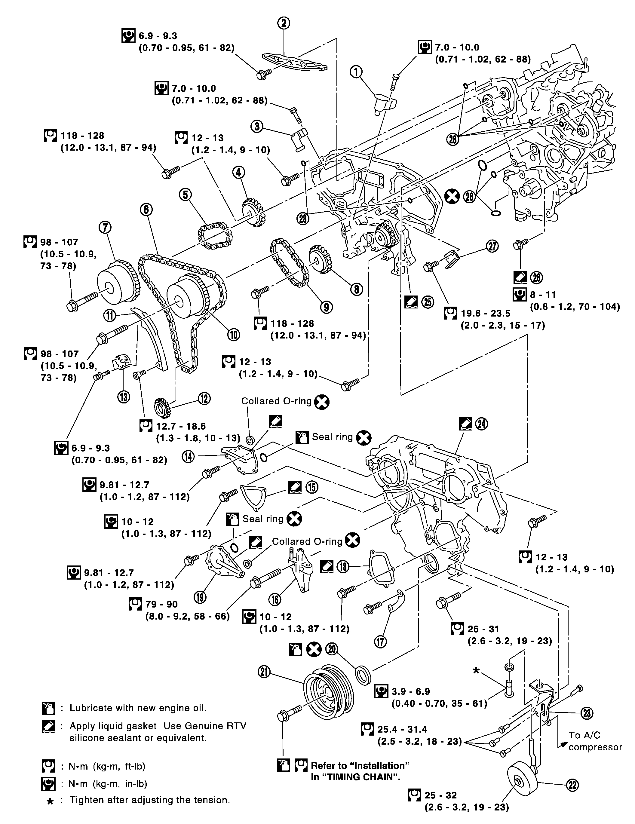
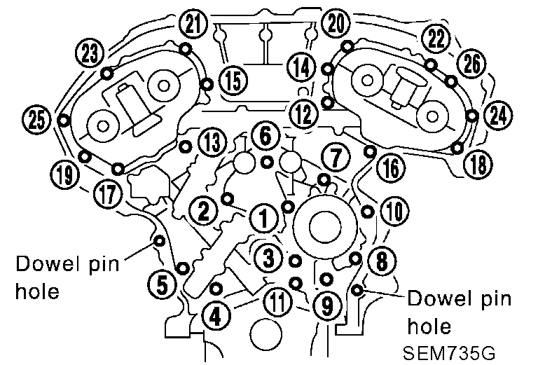
pic 1
Exploded view
pic 2
Legend
CAUTION:
- After removing timing chain, do not turn crankshaft and camshaft separately, or valves will strike piston heads.
- When installing camshafts, chain tensioners, oil seals, or other sliding parts, lubricate contacting surfaces with new engine oil.
- Apply new engine oil to bolt threads and seat surfaces when installing cylinder head, camshaft sprockets, crankshaft pulley and camshaft brackets.
- Before disconnecting fuel hose, release fuel pressure. Refer to Powertrain Management; Fuel Delivery and Air Induction.
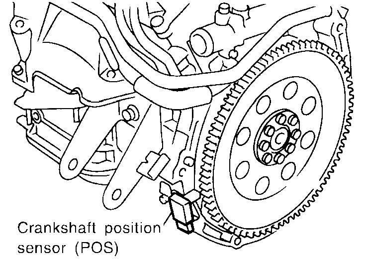
- When removing the oil pans, oil pump assembly and timing chain from engine, first remove the crankshaft position sensor (POS) from the assembly.
- Be careful not to damage sensor edges.
- Do not spill engine coolant on drive belts.
Removal
1. Drain engine oil.
2. Release fuel pressure. Refer to Power-train Management; Fuel Delivery and Air Induction.
3. Drain coolant by removing cylinder block drain plugs.
4. Remove ornament cover.
5. Remove air duct to intake manifold, collector, PCV hose, vacuum hoses, fuel hoses, wires, harness, connectors and so on.
6. Remove the following. Water hoses EVAP canister purge hose PCV hose PCV valve Water outlet
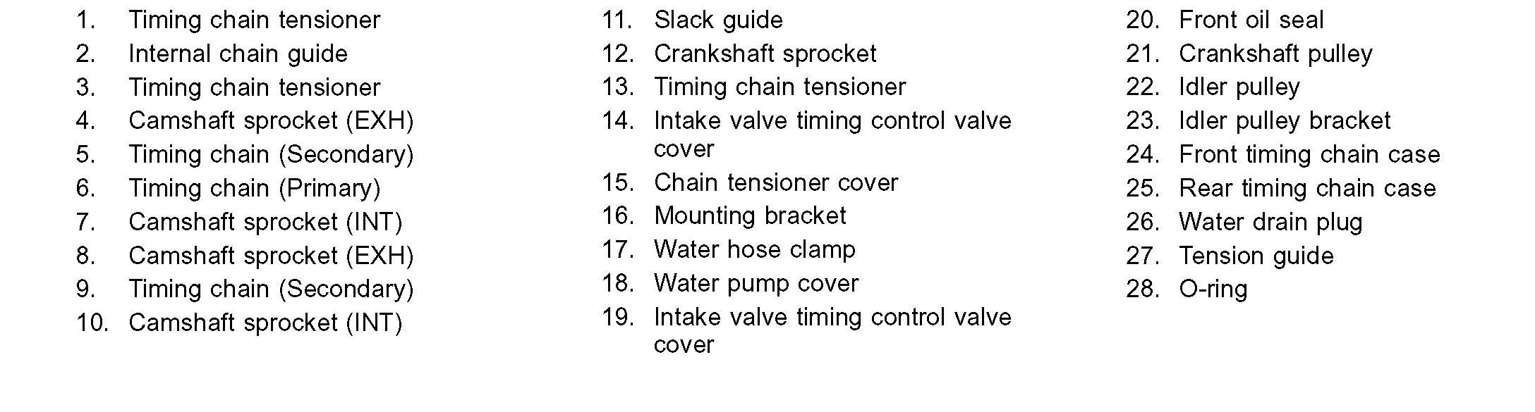
pic 3
7. Remove intake manifold upper and lower collectors loosening bolts and nuts in reverse order of tightening. Refer to "Tightening Procedures", under Engine; Service and Repair.
pic 4
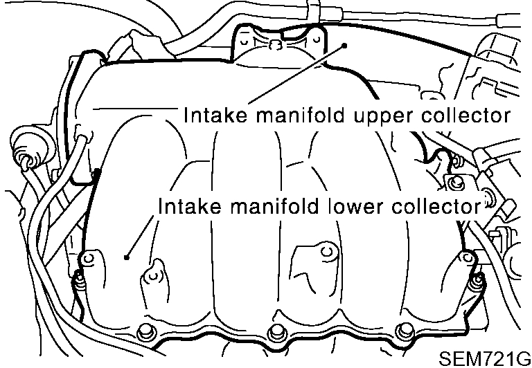
8. Remove RH and LH ignition coils.
pic 5
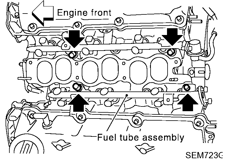
9. Remove fuel tube assembly.
pic 6
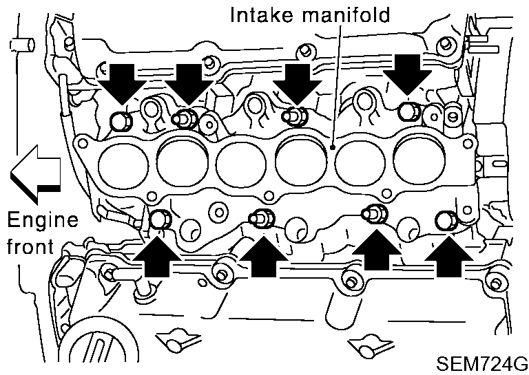
10. Remove intake manifold loosening bolts and nuts in reverse order of tightening. Refer to "TIGHTENING PROCEDURES", under Engine; Service and Repair.
pic 7
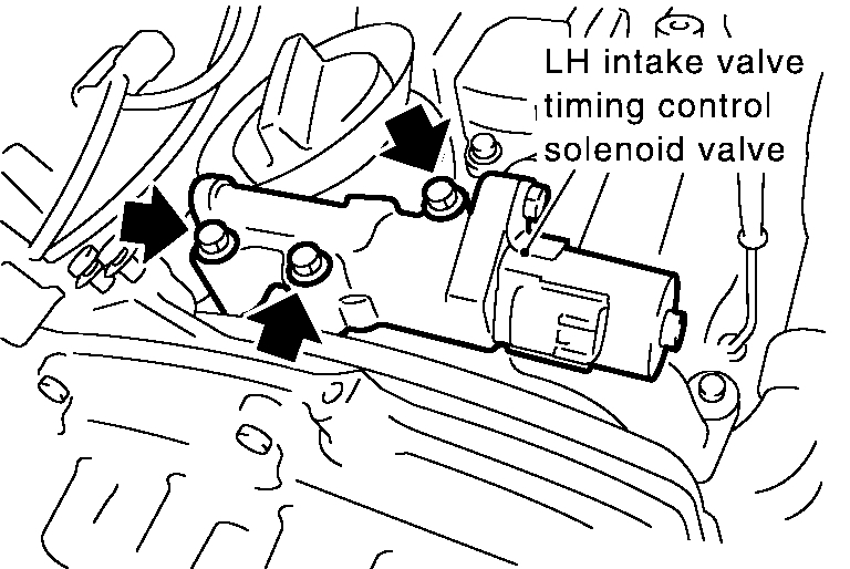
11. Remove RH and LH intake valve timing control solenoid valves.
pic 8
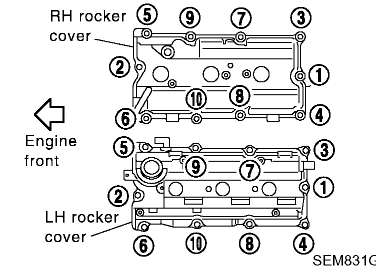
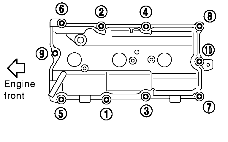
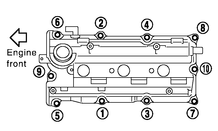
12. Remove RH and LH rocker covers from cylinder head.
- Loosen bolts in numerical order shown in the figure.
13. Remove engine undercover.
14. Remove front RH wheel and engine side cover.
15. Remove drive belts and idler pulley bracket.
16. Remove power steering oil pump belt and power steering oil pump assembly.
pic 9
17. Remove crankshaft position sensor (POS).
pic 10
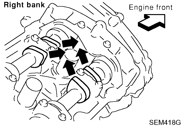
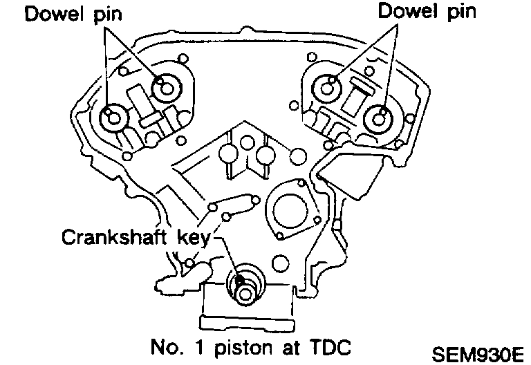
18. Set No.1 piston at TDC on the compression stroke by rotating crankshaft.
pic 11
- Check that intake and exhaust cam nose on No.1 cylinder are installed as shown. If not, turn the crankshaft one revolution (360°) and align as above.
pic 12
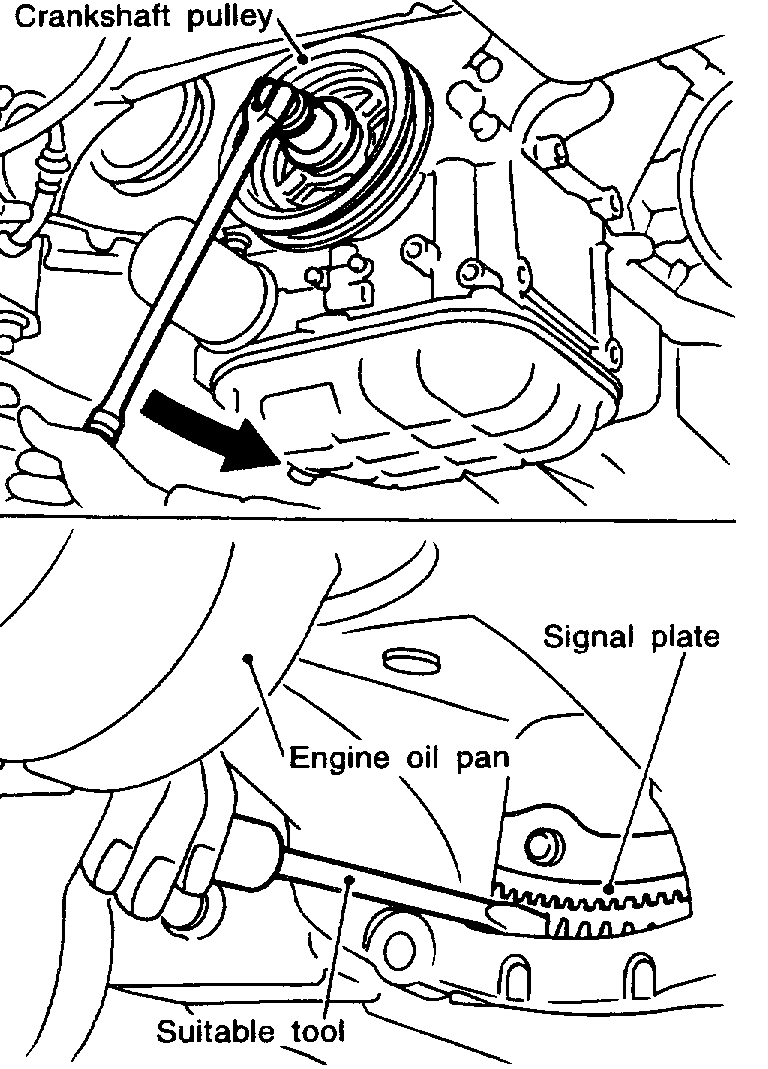
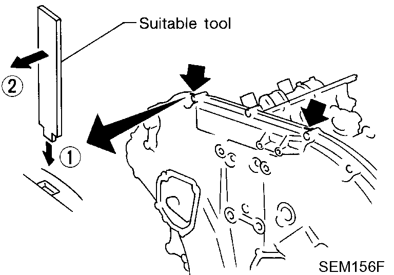
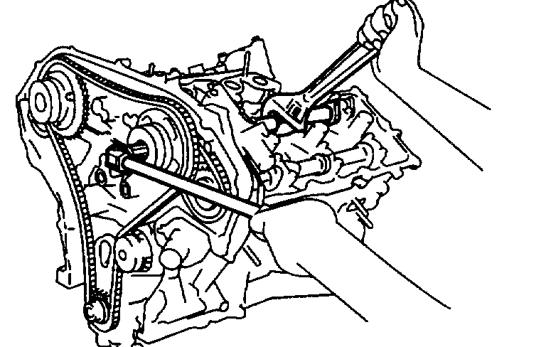
19. Loosen crankshaft pulley bolt. (At this time remove oil pan rear cover plate and set a suitable tool to ring gear so that crankshaft cannot rotate.)
- Be careful not to damage the signal plate teeth.
pic 13
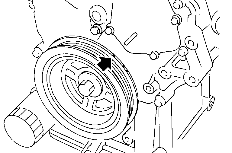
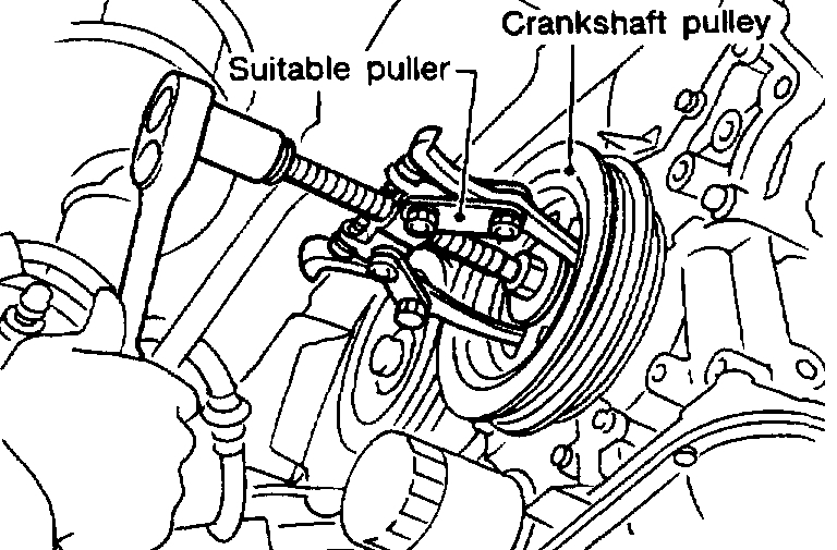
20. Remove crankshaft pulley with a suitable puller.
pic 14
21. Remove intake valve timing control valve covers.
- Loosen bolts in reverse order shown in the figure.
- In the cover, the shaft is engaged with the center hole of the intake camshaft sprocket. Remove it straight out until the engagement comes off.
22. Remove air conditioner compressor and bracket. Refer to Heating and Air Conditioning; Air Conditioning.
23. Remove front exhaust tube and its support.
24. Hang engine at right and left side engine slingers with a suitable hoist.
25. Remove right side engine mounting, mounting bracket and nuts.
26. Remove center member assembly.
27. Remove upper and lower oil pans.
pic 15
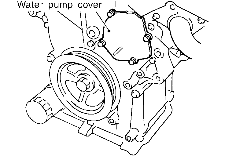
28. Remove water pump cover.
pic 16
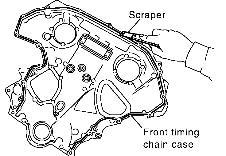
29. Remove front timing chain case bolts.
- Loosen bolts in reverse order shown in the figure.
pic 17
30. Remove front timing chain case.
- Do not scratch sealing surfaces.
31. Remove timing chain tensioner cover from front timing chain case.
32. Remove front oil seal from front timing chain case.
pic 18
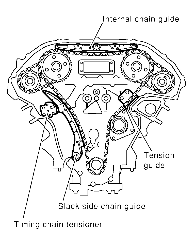
33. Remove internal chain guide.
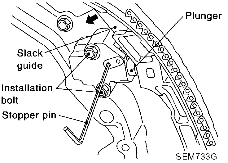
34. Remove timing chain tensioner and slack side chain guide.
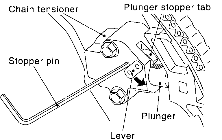
Remove chain tensioner as follows:
pic 19
a. Pull lever down, and release plunger stopper tab.
- Plunger stopper tab can be pushed up to release (coaxial structure with lever).
b. Insert stopper pin into tensioner body hole to fix lever, and keep the tab released.
- In figure, Allen wrench [2.5 mm (0.098 inch)] is used for stopper pin as an example.
pic 20
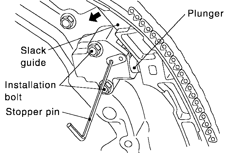
c. Insert plunger into tensioner body by pressing slack guide.
d. Keep slack guide pressed, and fix it by pushing stopper pin through lever hole and body hole.
e. Remove mounting bolts, and remove chain tensioner.
pic 21
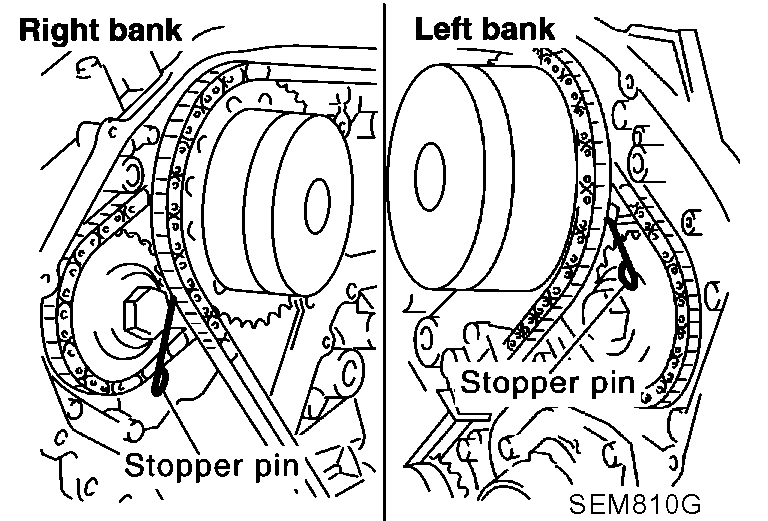
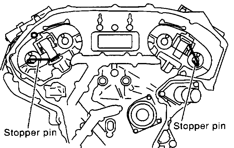
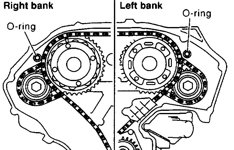
35. Attach a suitable stopper pin to RH and LH camshaft chain tensioners. (For secondary timing chains)
pic 22
36. Remove intake and exhaust camshaft sprocket bolts.
- Apply paint to timing chain and camshaft sprockets for alignment during installation.
- Secure the hexagonal portion of the camshaft using a spanner to loosen mounting bolts.
37. Remove primary and secondary timing chains with camshaft sprockets.
- Intake camshaft sprocket is two-for-one structure of primary and secondary sprockets.
- Handle intake camshaft sprocket, taking care of the following.
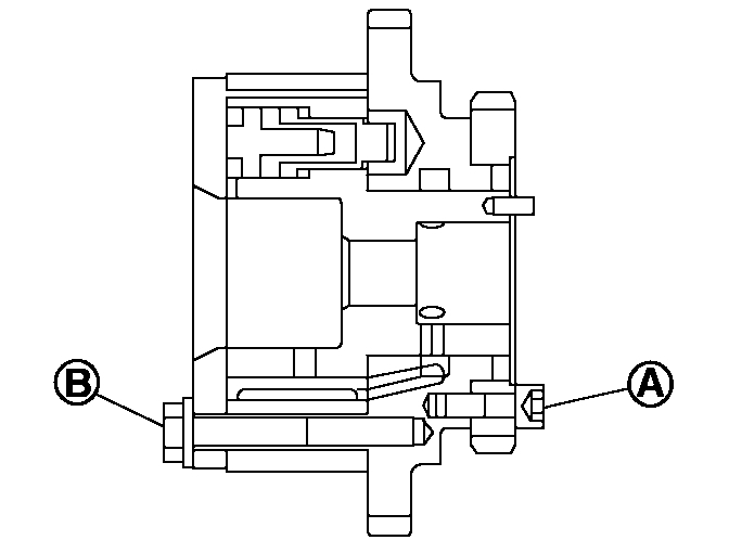
pic 23
CAUTION: Avoid impact. Do not disassemble (Never loosen bolts A and B).
38. Remove chain tension guide and crankshaft sprocket.
pic 24
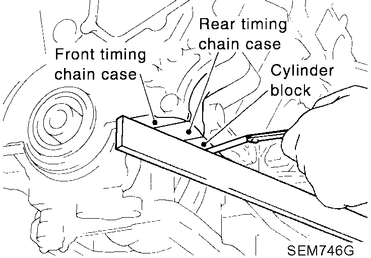
39. Remove rear timing chain case as follows.
a. Loosen mounting bolts in reverse order shown in figure, and remove them.
b. Disconnect liquid gasket applied portion using seal cutter (special service tool: KV10111100) or an equivalent tool. Then remove rear timing chain case.
40. Remove RH and LH camshaft chain tensioners from cylinder head as follows.
a. Remove No.1 camshaft brackets.
b. Remove chain tensioners with stopper pin attached.
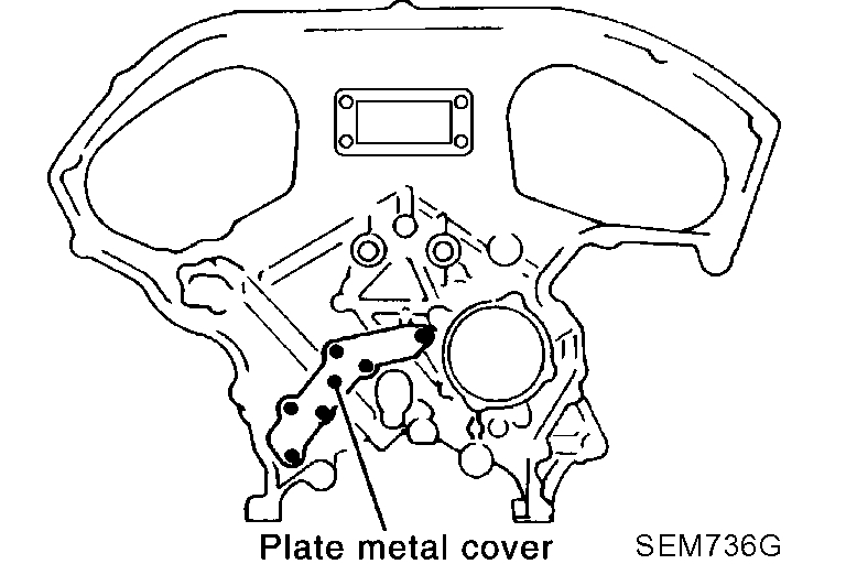
pic 25
CAUTION: Do not remove plate metal cover of oil passage. After removing chain case, do not apply any load which affects flatness.
pic 26
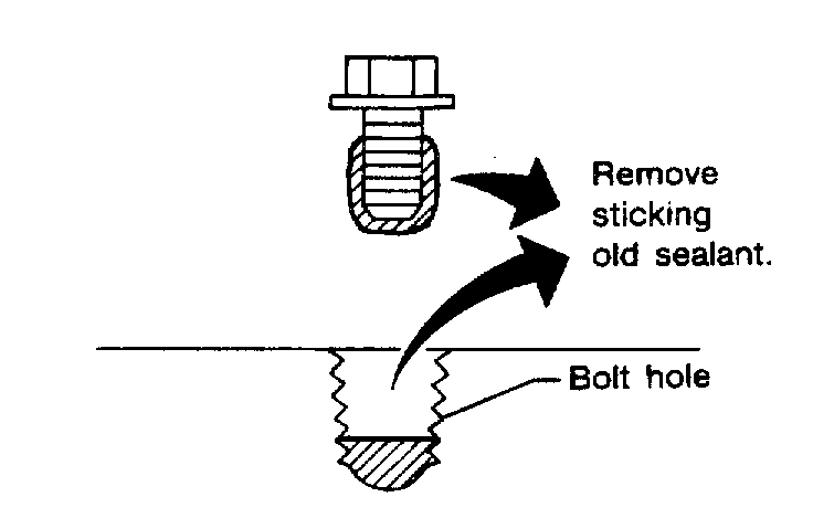
41. Use a scraper to remove all traces of liquid gasket from front timing chain case.
pic 27
- Remove old liquid gasket from the bolt hole and thread.
pic 28
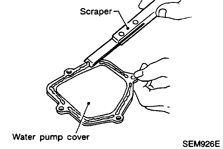
42. Use a scraper to remove all traces of liquid gasket from water pump cover and intake valve timing control solenoid valve covers.
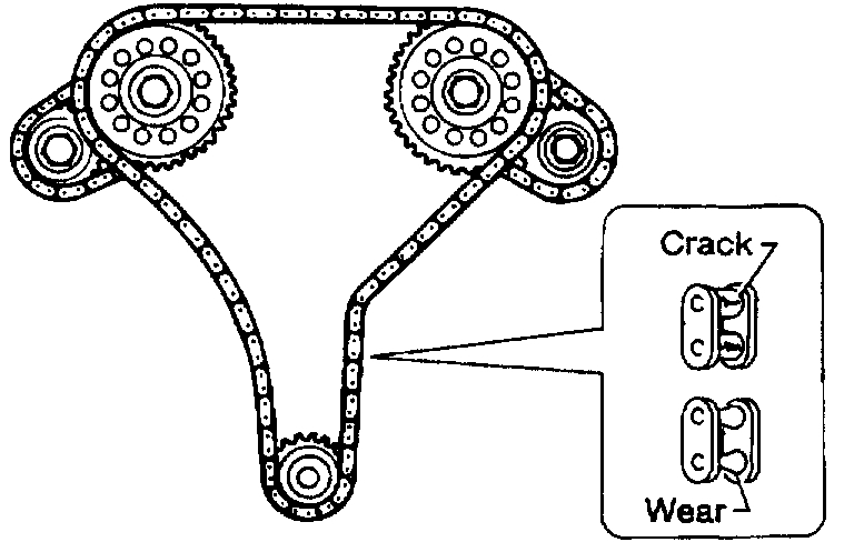
Inspection
pic 29
Check for cracks and excessive wear at roller links. Replace chain if necessary.
Installation
1. Install RH and LH camshaft chain tensioners to cylinder head as follows.
a. Install chain tensioners with stopper pin attached and new O-ring.
b. Install No.1 camshaft brackets.
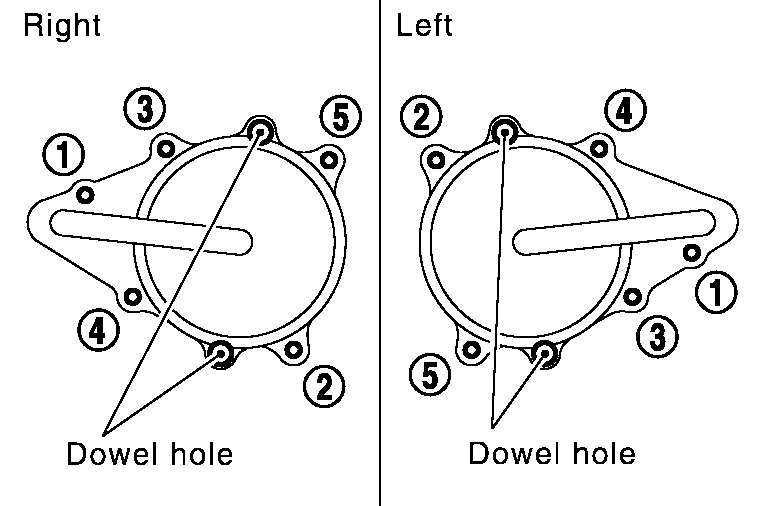
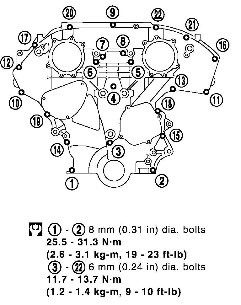
2. Apply liquid gasket to rear timing chain case.
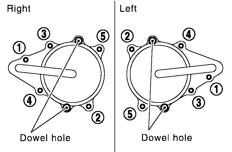
3. Align rear timing chain case and water pump assembly with dowel pins (RH and LH) on cylinder block. Then install it.
- Do not allow O-ring to drop.
pic 30
a. Tighten mounting bolts in order as shown in the figure.
- Install two types of mounting bolts, referring to the following instructions and figure.
Bolt length:
20 mm (0.79 inch) (1, 2, 3, 6, 7, 8, 9, and 10 in the figure)
16 mm (0.63 inch) (other than the above)
Tightening torque: 12 - 13 Nm (1.2 - 1.4 kg-m, 9 - 10 ft. lbs.)
b. After all bolts are temporarily tightened, retighten them to specified torque in order shown in the figure.
4. Install chain tension guide.
5. Make sure that camshaft and crankshaft are at TDC position of No.1 cylinder.
pic 31
- Make sure that knock pin hole, knock pin and crankshaft key are located as shown in the figure.
- Camshaft knock pin hole (intake-side): At cylinder head upper face side in each bank
- Camshaft knock pin (exhaust-side): At cylinder head upper face side in each bank
- Crankshaft key: At cylinder head side of RH bank
CAUTION: Hole on small diameter side must be used for intake knock pin. Do not misidentify (Ignore big diameter side).
pic 32
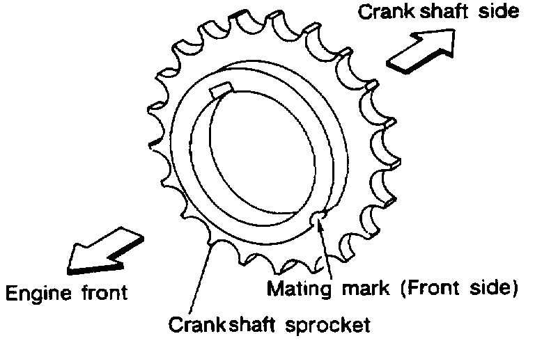
6. Install crankshaft sprocket.
- Install it, with matching mark to timing chain facing front of engine.
pic 33
7. Install secondary timing chain and camshaft sprocket.
CAUTION: Matching marks between timing chain and sprockets slip easily. Confirm all matching mark positions repeatedly during the installation process.
- Push sleeve of secondary chain tensioner, and keep it pressed with stopper pin.
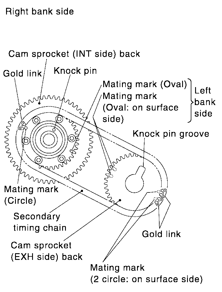
a. Align matching marks on secondary timing chain (gold link) with the ones on intake and exhaust sprockets (stamped). Then install them.
- Matching marks of intake sprocket are on back side of secondary sprocket.
pic 34
- There are two types of matching marks, round and oval types. They should be used for RH/LH banks respectively.
RH bank: Use round type.
LH bank: Use oval type.
b. Align knock pin and pin hole on camshaft with groove and knock pin on sprocket. Then install them.
- On intake side, align pin hole on small diameter side of camshaft front end with knock pin on back side of camshaft sprocket. Then install them.
- On exhaust side, align knock pin on camshaft front end with pin groove on camshaft sprocket. Then install them.
- Mounting bolts for camshaft sprockets must be tightened in step 7. Tightening them by hand is enough to prevent dislocation of knock pins.
pic 35
- It may be difficult to visually check the dislocation of mating marks during and after installation. To make the matching easier, make a mating mark on the sprocket teeth in advance using paint.
pic 36
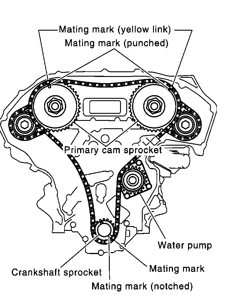
8. Install secondary timing chain and sprocket to the other bank. Install primary timing chain at the same time.
- Installation of the secondary timing chain follows the procedure described in step 6.
- Install primary timing chain so that mating mark (punched) on camshaft sprocket is aligned with that (yellow link) on the timing chain, and mating mark (notched) on crankshaft sprocket is aligned with that on the timing chain, respectively.
- When it is difficult to align mating marks of the primary timing chain with each sprocket, gradually turn the camshaft hexagonal portion using a spanner so it is aligned with the mating mark.
- During alignment, be careful to prevent dislocation of mating marks on the secondary timing chain.
pic 37
9. After confirming the mating marks are aligned, tighten the camshaft sprocket mounting bolts.
- Secure the camshaft hexagonal portion using a spanner to tighten mounting bolts.
pic 38
10. Pull out the stopper pin from the secondary timing chain tensioner.
pic 39
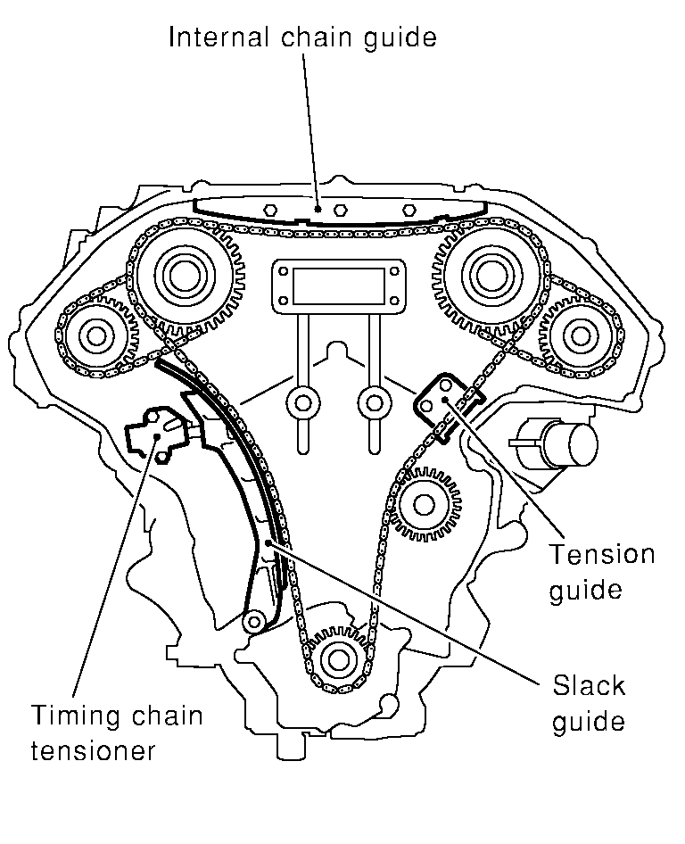
11. Install internal chain guide.
12. Install slack guide.
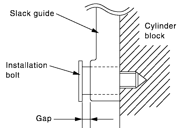
pic 40
- Take care not to overtighten mounting bolts for slack guide. It is normal for a gap to exist under bolt seats when mounting bolts are tightened to specified torque.
pic 41
13. Install chain tensioner for slack guide.
- When installing chain tensioner, push in sleeve and keep it pressed with stopper pin.
- Remove dirt and foreign materials completely from back and mounting surfaces of chain tensioner.
- After installing, pull out stopper pin by pressing slack guide.
14. Confirm again that matching marks on sprockets and timing chain have not slipped.
pic 42
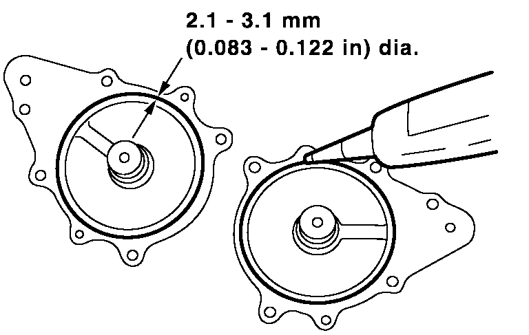
15. Install front oil seal to front timing chain case.
pic 43
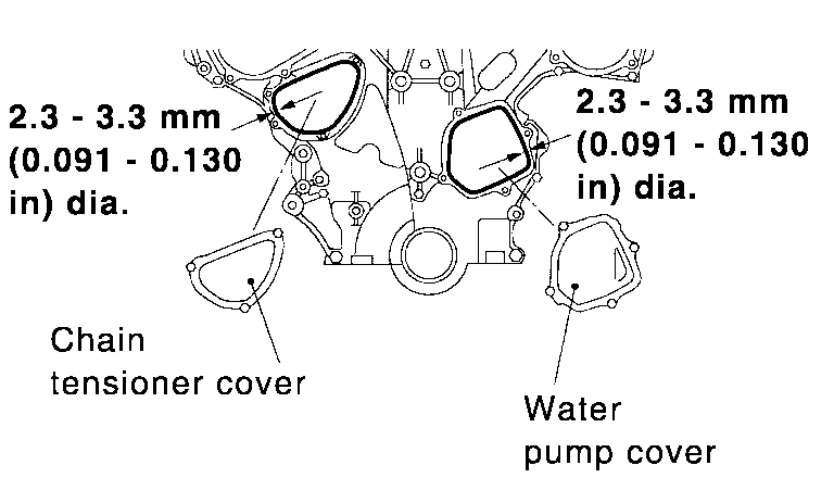
16. Apply liquid gasket to water pump cover and chain tensioner cover. Before installation, wipe off the protruding sealant.
17. Install water pump cover and chain tensioner cover.
pic 44
18. Install O-rings on rear timing chain case.
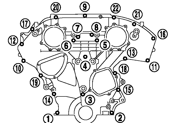
19. Apply liquid gasket to front timing chain case.
- Before installation, wipe off the protruding sealant.
20. Install front timing chain case.
- Align dowel pin on rear timing chain case with hole on front timing chain case.
pic 45
21. Tighten bolts to the specified torque in order shown in the figure.
pic 46
22. After installing front timing chain case, check surface height difference between following parts on oil pan mounting surface.
Standard
Front timing chain case to rear timing chain case: -0.14 to 0.14 mm (-0.0055 to 0.0055 inch)
Oil pump to cylinder block: -0.36 to -0.10 mm (-0.0142 to -0.0039 inch)
Rear timing chain case to cylinder block: -0.24 to 0.14 mm (-0.0094 to 0.0055 inch)
- If not within standard, repeat above installation procedure.
23. Install intake valve timing control valve cover.
a. Install new O-rings at front timing chain case.
b. Install new seal ring at intake valve timing control valve cover with new engine oil applied on it.
pic 47
c. Apply liquid gasket to intake valve timing control valve covers. Use genuine RTV silicone sealant or equivalent.
- Being careful not to move the seal ring from the installation groove, align the dowel pins on the chain case with the holes to install the intake valve timing control valve cover.
pic 48
- Tighten in numerical order as shown in the figure.
24. Install RH and LH rocker covers. Rocker cover tightening procedure:
pic 49
RH rocker cover
pic 50
LH rocker cover
- Tighten in numerical order as shown in the figure.
a. Tighten bolts 1 to 10 in that order to 0.96 to 2.96 Nm (0.10 to 0.30 kg-m, 9 to 26 inch lbs.).
b. Then tighten bolts 1 to 10 as indicated in figure to 7.33 to 9.33 Nm (0.75 to 0.95 kg-m, 65 to 82 inch lbs.).
25. Install intake manifold. Tighten intake manifold nuts and bolts.
26. Install fuel tube assembly.
27. Install intake manifold collector gasket.
28. Install intake manifold upper and lower collectors.
29. Install RH and LH ignition coils.
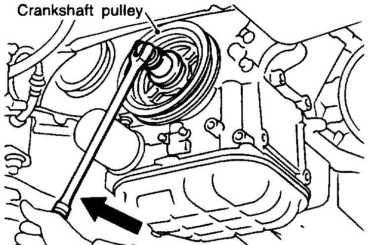
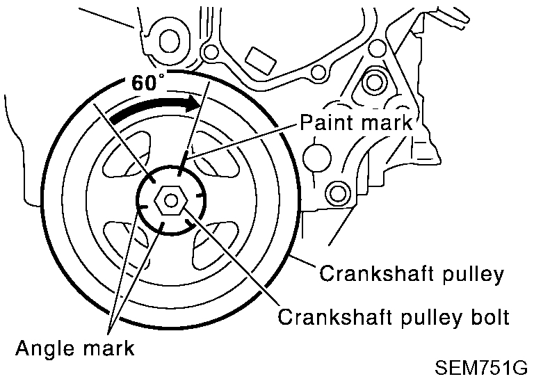
30. Install crankshaft pulley to crankshaft.
pic 51
a. Tighten to 39 to 49 Nm (4.0 to 5.0 kg-m, 29 to 36 ft. lbs.).
b. Put a paint mark on the crankshaft pulley.
pic 52
c. Again tighten by turning 60° to 66°, about the angle from one hexagon bolt head corner to another.
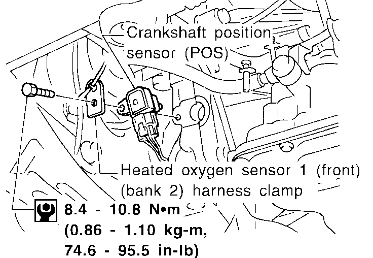
31. Reinstall removed parts in reverse order of removal.
pic 53
- Make sure that crankshaft position sensor (POS) and heated oxygen sensor 1 (front) (bank 2) harness clamp are installed correctly as shown in figure.
- When installing fuel tube assembly.
- After starting engine, keep idling for three minutes. Then rev engine up to 3,000 rpm under no load to purge air from the high-pressure chamber of the chain tensioners. The engine may produce a rattling noise. This indicates that air still remains in the chamber and is not a matter of concern.
__________________________________
I hope this helps. Let me know if you have questions.
Take care,
Joe
Images (Click to enlarge)
Jul 29, 2020 at 8:48 PM