Hi and thanks for using 2CarPros.
This engine is an interference engine. So, if it is out of time, it will most likely cause internal damage.
With that in mind, here are the directions specific to your vehicle for replacing the belt. Check through it to confirm everything you did correlates with what is shown in these directions. Also, turn the engine by hand several revolutions to make sure nothing is hitting internally. The pictures attached correlate with these directions.
________________________________________
TIMING BELT, REPLACING
Timing belt, replacing
Special tools:
999 5433 COUNTERHOLD See: Vehicle > Electrical / Mechanical Repair > 999 5433 Counterhold
Remove components
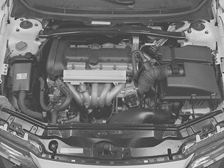
Picture 1
Caution! Remove the ignition key.
Remove:
- the cross stay between the suspension turrets
- the upper camshaft belt cover
- the servo reservoir and expansion tank.
Lift them up and place them on top of the engine
Warning! Ensure that no power steering fluid is spilled. It is extremely flammable!
- the auxiliaries belt
- the front camshaft belt cover.
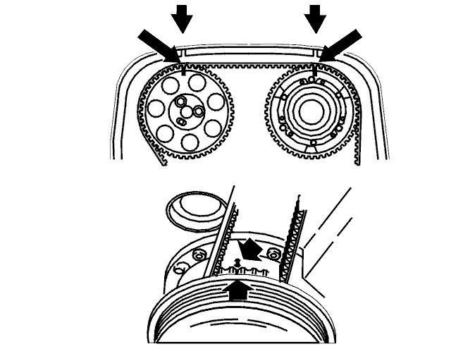
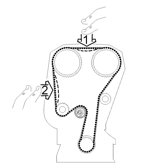
Position the engine according to the marking
Picture 2
Remove the right front wheel.
Remove the nut from the cover in the fender liner.
Install the upper camshaft belt cover.
Turn the crankshaft clockwise until the markings on the crankshaft and camshaft pulley correspond.
Turn the crankshaft a further 1/4 turn clockwise and then back again until the markings correspond. The markings are illustrated.
Remove the upper camshaft belt cover.
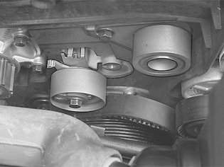
Removing the camshaft belt
Picture 3
Slacken off the belt tensioner.
There are two variants of the belt tensioner.
Up to engine number 3188688 the eccentric must be turned clockwise when loosening.
From engine number 3188689 the eccentric must be turned anticlockwise to loosen the belt tension.
- Slacken off the belt tensioner center screw slightly.
- Hold the center screw in position and, depending on the variant, turn the eccentric on the tensioner to 10 o'clock (clockwise) or 2 o'clock (anticlockwise) using a 6 mm allen key.
- Remove the camshaft belt from the tension pulley, camshaft pulley and water pump.
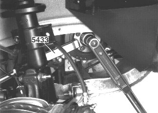
Picture 4
Remove the vibration damper.
Remove the oscillation damper. Use counterhold 999 5433 COUNTERHOLD See: Vehicle > Electrical / Mechanical Repair > 999 5433 Counterhold. Work the oscillation damper loose.
Remove the camshaft belt.
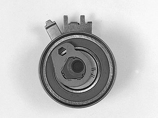
Checking the tension pulley and idler pulley
Picture 5
Check for bearing wear:
Spin the idler pulley and listen for noise. If replacing with a new idler pulley, tighten to 24 Nm.
Spin the tension pulley and listen for noise. When replacing, screw the tension pulley into place with the center screw.
spin the tension pulley and listen for noise. If replacing, screw the tension pulley into place with the center screw.
Screw in the center screw by hand.
Ensure that the tensioner fork is centered over the cylinder block rib.
Ensure that the allen hole on the eccentric is at "10 o'clock".
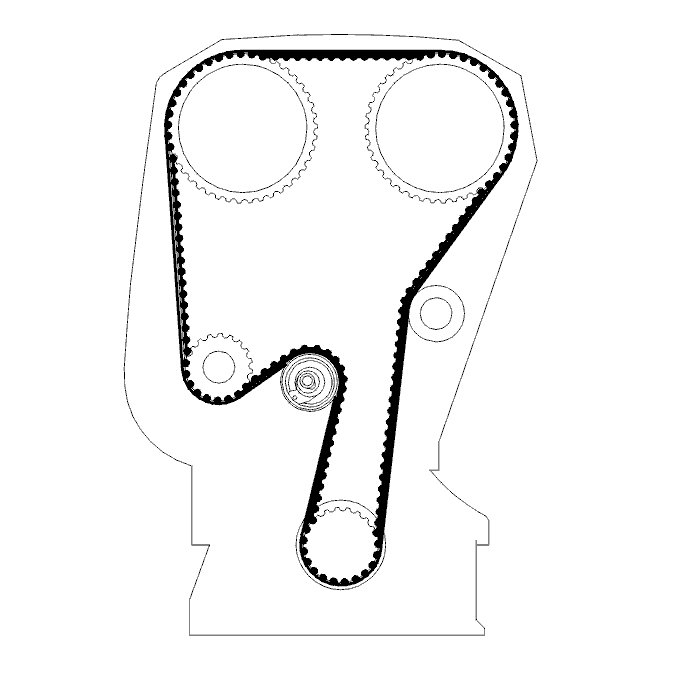
Installing the camshaft belt
Picture 6
Note: For information regarding Variable Valve Timing see: Variable Valve Timing Actuator, Adjustments See: Variable Valve Timing Actuator > Adjustments
Also see Belt Drive, Assembly See: Timing Belt > Removal and Replacement > Belt Drive, Assembly
Install the camshaft belt over pulley wheel on the crankshaft.
Install the oscillation damper. Tighten the center nut to 180 Nm. Use counterhold 999 5433 COUNTERHOLD See: Vehicle > Electrical / Mechanical Repair > 999 5433 Counterhold.
Remove the counterhold and install new screws. Tighten the screws to 25 Nm. Angle-tighten 30°
Install the new belt in the following order:
- crankshaft
- idler pulley
- intake camshaft pulley
- exhaust camshaft pulley
- water pump
- belt tensioner.
Tighten the timing belt
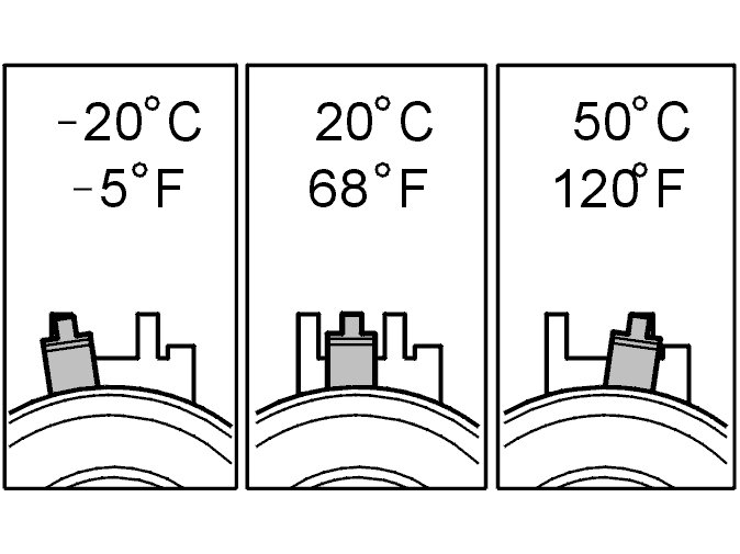
Picture 7
This adjustment is to be made with a cold engine. A suitable temperature is approximately 20°C/68°F.
At higher temperatures, for example with engine at operating temperature or at higher ambient temperature, the needle is further to the right.
The position of the needle, when aligning the camshaft belt tensioner at different engine temperatures, is shown in the illustration.
Picture 8
Tighten the timing belt:
There are two variants of the belt tensioner.
From engine number 3188688 the eccentric must be turned anticlockwise to tighten the belt.
From engine number 3188689 the eccentric must be turned clockwise to tension the belt.
- turn the crankshaft clockwise carefully until the camshaft belt is tensioned. The belt should be tight between the intake camshaft pulley, idler pulley and crankshaft.
- hold the center screw on the belt tensioner in position and turn the eccentric on the belt tensioner clockwise/anticlockwise, depending on the variant, until the tensioner's needle passes the marked position.
Then turn the eccentric back so that the indicator reaches the marked position in the center of the window.
- Secure the eccentric and tighten the center screw to 20 Nm.
Check that the needle is in the correct position.
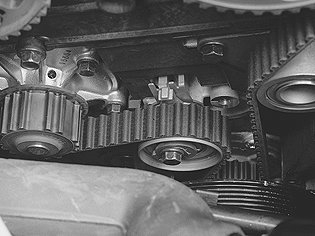
Check
Picture 9
Checking markings:
- press the belt to check that the indicator on the tensioner moves easily.
- install the upper timing belt cover.
- turn the crankshaft 2 turns and check that the markings on the crankshaft and camshaft pulley correspond.
- check that the indicator on the belt tensioner is within the marked area.
Reinstall
Picture 10
Reinstall the removed components:
- the front camshaft belt cover.
Tighten to 12 Nm
- the upper camshaft belt cover
- install the auxiliaries belt
- the servo reservoir
- the expansion tank
Note! Ensure that the hoses are correctly positioned.
- the cross member. Tighten the screws at the suspension turret to 50 Nm and the screw for the engine bracket to 80 Nm.
Wipe clean and check the engine compartment
- the cover in the fender liner
- the front wheel according to Installing wheels See: Wheels > Removal and Replacement.
Checking work
Function test:
- Test drive the engine.
____________________________________
:Let me know if this helps or if you have other questions.
Take care,
Joe
Images (Click to enlarge)
Mar 7, 2019 at 7:43 PM