Hi, just to jump in and add to it. I recommend you check the valve clearance first. Very common problem with Honda where the exhaust valves get too tight and cause this condition. Here are the instructions on how to check and adjust the valves. I recommend you let the vehicle sit overnight and do the adjustment when cold.
Collision
Search vehicle information
17
1999 Honda Civic DX Sedan L4-1590cc 1.6L SOHC MFI
Adjustments
Vehicle Powertrain Management Tune-up and Engine Performance Checks Valve Clearance Adjustments
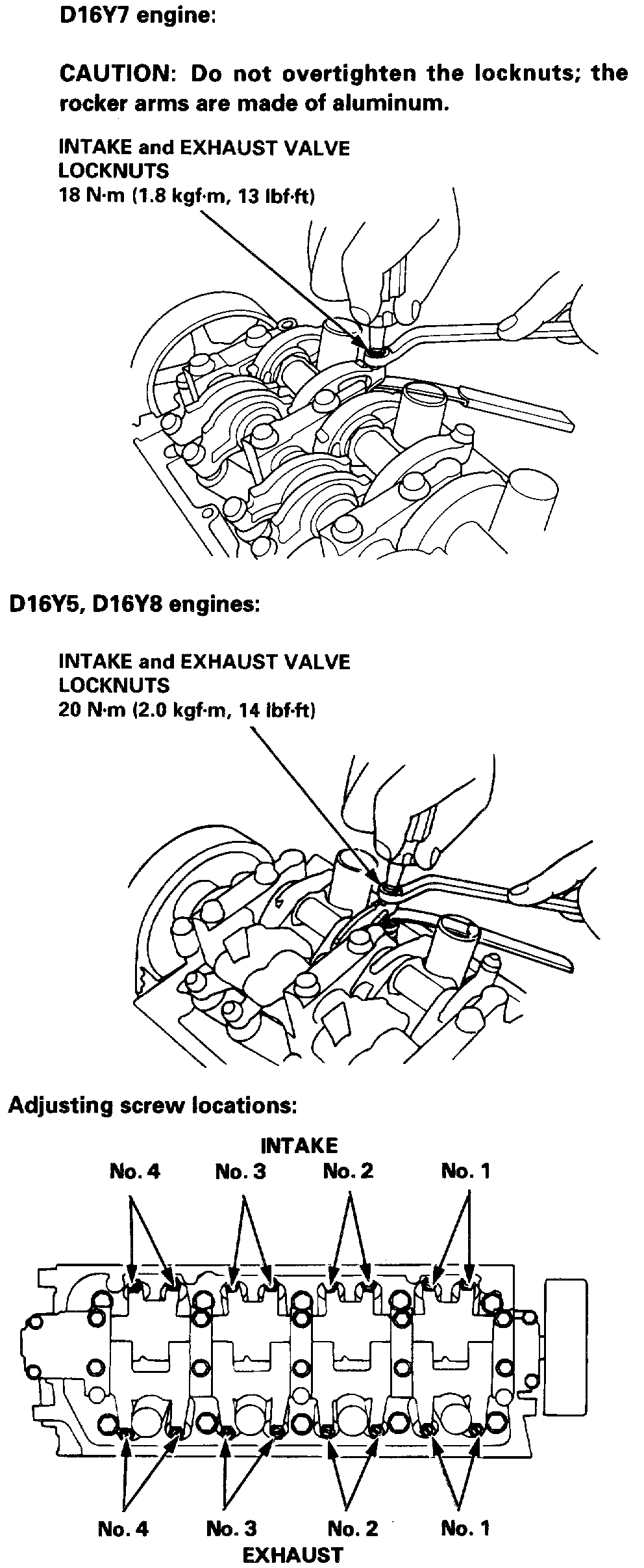
ADJUSTMENTS
NOTE:
- Valves should be adjusted only when the cylinder head temperature is less than 100°F (38°C).
- After adjusting, retorque the crankshaft pulley bolt.
1. Remove the cylinder head cover.
2. Remove the upper cover.
ImageOpen In New TabZoom/Print
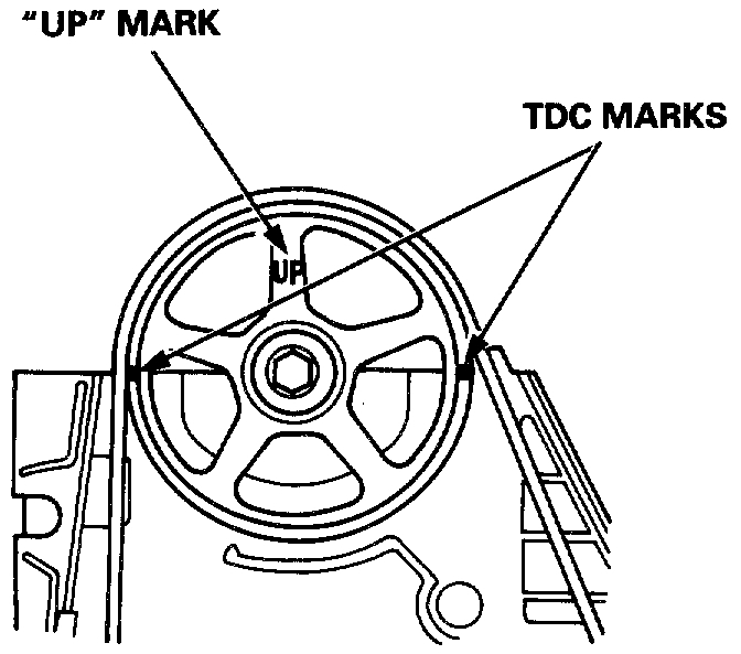
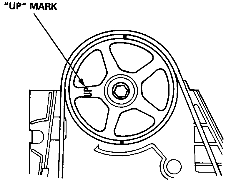
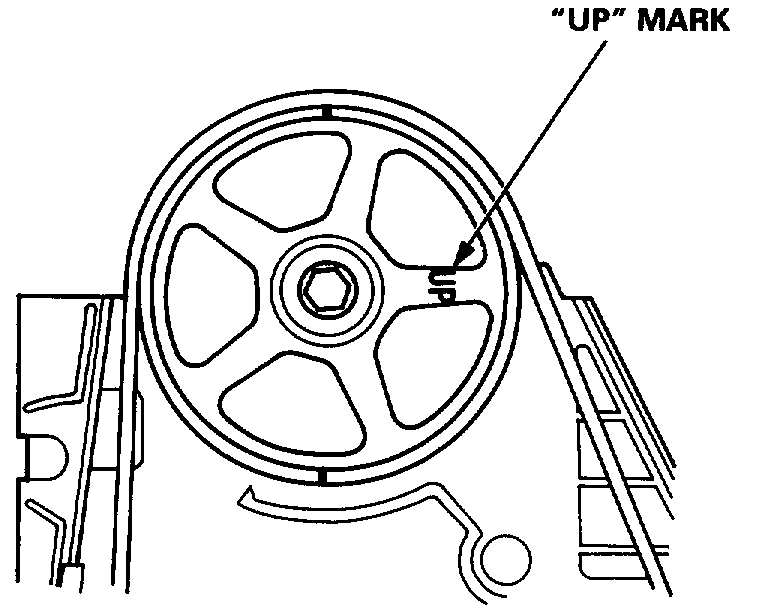
3. Set the No. 1 piston at TDC. The "UP" mark on the cam-shaft pulley should be at top, and the TDC marks should align with the cylinder head surface.
4. Adjust valves on No. 1 cylinder.
Intake: 0.18 - 0.22 mm (0.007 - 0.009 inch)
Exhaust: 0.23 - 0.27 mm (0.009 - 0.011 inch)
imageOpen In New TabZoom/Print
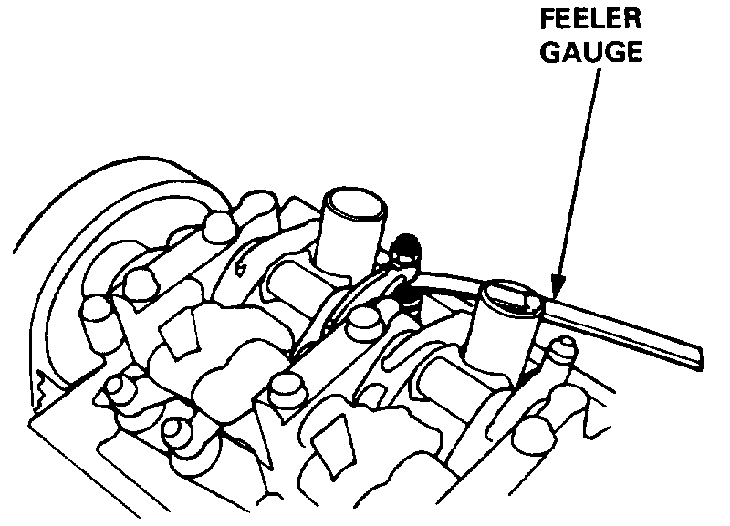
5. Loosen the locknut, and turn the adjustment screw until the feeler gauge slides back and forth with a slight amount of drag.
ImageOpen In New TabZoom/Print
6. Tighten the locknut, and check the clearance again. Repeat the adjustment if necessary.
ImageOpen In New TabZoom/Print
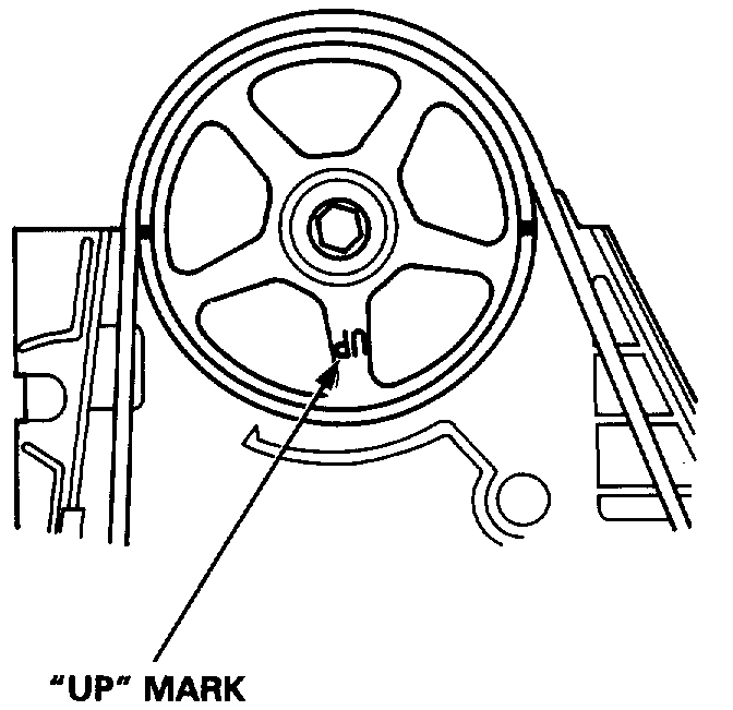
7. Rotate the crankshaft 180° counterclockwise (camshaft pulley turns 90°). The "UP" mark should be on the exhaust side. Adjust valves on No. 3 cylinder.
ImageOpen In New TabZoom/Print
8. Rotate the crankshaft 180° counterclockwise to bring No. 4 piston to TDC. Both TDC grooves are once again visible. Adjust valves on No. 4 cylinder.
ImageOpen In New TabZoom/Print
9. Rotate the crankshaft 180° counterclockwise to bring No. 2 piston to TDC. The "UP" mark should be on the intake side. Adjust valves on No. 2 cylinder.
Follow the firing order and let us know what the valve clearance looks like.
Images (Click to make bigger)
Wednesday, May 1st, 2019 AT 11:24 PM