Welcome to 2CarPros.
It has struts on the front and shocks on the rear. Here are the directions for replacing the rear shocks. The attached pictures correlate with these directions.
_____________________
Shock Absorber, FWD
Vehicle Steering and Suspension Suspension Suspension Strut / Shock Absorber Service and Repair Removal and Replacement Self-Leveling Suspension Shock Absorber, FWD
SHOCK ABSORBER, FWD
Shock Absorber, FWD
Special tools, testers and auxiliary items required
Torque Wrench 1332 40-200Nm (VAG1332)
Removing
- Remove the wheel.
- Remove the wheel housing liner.
For the Left Shock Absorber Only
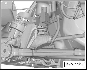
- Remove the Left Rear Level Control System Sensor (G76) from the lower transverse link.
Continuation for Both Sides
- Remove coil spring. Refer to => [ Coil Spring ] See: Suspension > Removal and Replacement > Coil Spring.
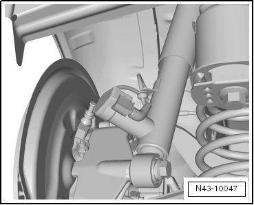
- Disconnect the connector and remove the wire from the shock absorber
pic 1
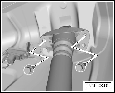
- Remove the shock absorber bolts.
Pic 2
For the Left Shock Absorber Only
- Remove the Rear Body Acceleration Sensor (G343) from the shock absorber mount.
Continuation for Both Sides
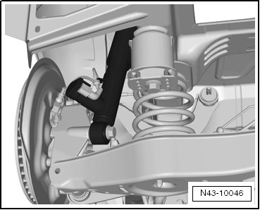
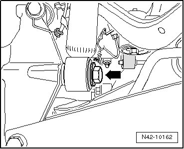
- Remove bolt - arrow -.
Pic 3
- Remove shock absorber.
Installing
Install in reverse order of removal. Note the following:
The bolted connections of the shock absorber to the wheel bearing housing must only be fastened when the dimension "a" is achieved! Refer to => [ Tightening of the respective bolts/nuts must then only occur after dimension between the wheel hub center and the lower edge of wheel housing has been attained. ] See: Suspension > Components > Rear Axle, Lifting to Curb Weight Position.
Note the shock absorber installation position.
Pic 4
The Left And Right Rear Dampening Adjustment Valve (N338/N339) must point toward the outside of the rear wheel.
For the Left Shock Absorber Only
- Mount the rear body acceleration sensor on the shock absorber mount
pic 5
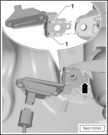
- Mount the retainer on the shock absorber mount from the rear, so that the retainer tabs - 1 - fit into the depressions on the shock absorber mount.
- Turn the retainer forward so that it contact the shock absorber mount.
The tab - arrow - is used for adjusting the rear body acceleration sensor retainer.
Continuation for Both Sides
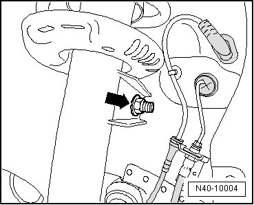
- Install the shock absorber and tighten the bolts.
- Tighten the bolt - arrow -.
Pic 6
- Connect the connector to the Left And Right Rear Dampening Adjustment Valve (N338/N339).
- Install coil spring. Refer to => [ Coil Spring ] See: Suspension > Removal and Replacement > Coil Spring.
For the Left Shock Absorber Only
- Connect the Left Rear Level Control System Sensor (G76) to lower transverse link.
Continuation for Both Sides
- Install wheel housing liner.
- Install the wheel and tighten the wheel bolts. Refer to => [ Wheel Bolt Tightening Specification ] See: Wheel Stud / Lug Nut > Mechanical > Wheel Bolt Tightening Specification.
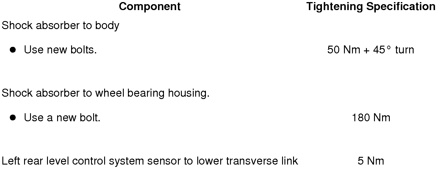
Tightening Specifications
pic 7
_____________________________________
Here are the directions for the front strut assemblies / removal and replacement. The remaining pictures correlate with these directions.
____________________________________
Suspension Strut
Special tools, testers and auxiliary items required
Torque Wrench 1332 40-200Nm (VAG1332)
Spreader Tool Tool (3424)
Engine/Gearbox Jack (VAG1383A)
Engine/Gearbox Jack Adapter - Wheel Hub Support (T10149)
Adaptive chassis DCC suspension strut, removing and installing, refer to => [ Suspension Strut ] See: Suspension Strut / Shock Absorber > Removal and Replacement > Suspension Strut.
Removing
- Loosen drive axle bolt to wheel hub:
Twelve-point bolt with ribs, refer to => [ Drive Axle Twelve-Point Bolt with Ribs, Loosening and Tightening ] See: Axle Nut > Procedures > Drive Axle Twelve-Point Bolt With Ribs, Loosening and Tightening.
Twelve-point bolt without ribs, refer to => [ Drive Axle Twelve-Point Bolt without Ribs, Loosening and Tightening ] See: Axle Nut > Procedures > Drive Axle Twelve-Point Bolt Without Ribs, Loosening and Tightening.
The wheel bearing must not be under a load while the drive axle threaded connection on the wheel side is loose.
If the wheel bearings are under the load of the vehicle's own weight, the wheel bearing will be damaged. This reduces the service life of the wheel bearings.
The drive axle bolt may be loosened maximum 90° when the vehicle is standing on its wheels.
Vehicles without a drive axle must not be moved, otherwise the wheel bearing will be damaged. If a vehicle must be moved, be sure to note the following:
Install an outer joint in place of the drive axle.
Tighten the outer joint to 120 Nm.
- Remove the wheel.
- Remove the nut - arrow - of the connecting link from suspension strut.
Pic 8
- Disengage wire for wheel speed sensor from suspension strut.
- Remove the level control system sensor from the control arm.
Pic 9
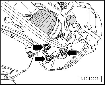
- Remove the nuts - arrows -.
Pic 10
- Remove both the wheel bearing housing and ball joint from the control arm.
- Remove the drive axle outer joint from the wheel hub.
- Secure drive axle to body using wire.
The drive axle must not hang down, otherwise the inner joint will be damaged by overflexing.
- Bolt ball joint to control arm again.
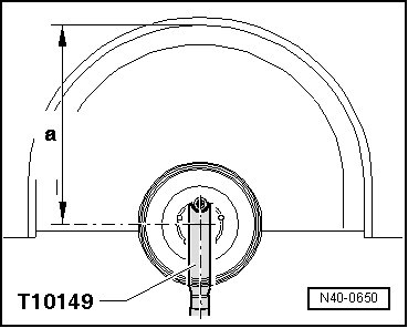
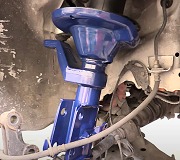
- Fasten Engine/Gearbox Jack (VAG1383A) using Engine/Gearbox Jack Adapter - Wheel Hub Support (T10149) to wheel hub with a wheel bolt.
Pic 11
Do not lift or lower vehicle when the Engine/Gearbox Jack (VAG1383A) stands below the vehicle. Vehicle could slip off lift.
Do not leave Engine/Gearbox Jack (VAG1383A) below vehicle any longer than necessary.
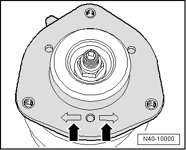
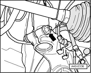
- Disconnect threaded connection of wheel bearing housing/suspension strut - arrow -.
Pic 12
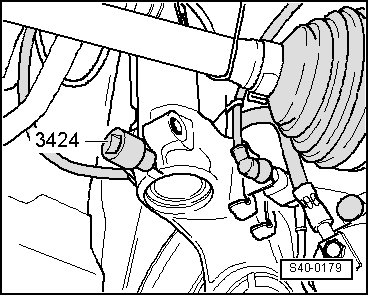
- Insert Spreader Tool Tool (3424) into slot of wheel bearing housing.
Pic 13
- Using a ratchet and the Spreader Tool Tool (3424), open the wheel bearing housing slot.
- Press brake disc in direction of suspension strut by hand.
Otherwise strut tube may be canted in hole of wheel bearing housing.
- Pull off wheel bearing housing downward from strut tube and lower using Engine/Gearbox Jack (VAG1383A) as far until strut tube hangs freely.
- Tightly tie wheel bearing housing to console/subframe using binding wire.
- Remove Engine/Gearbox Jack (VAG1383A) from below wheel bearing housing.
Do not leave Engine/Gearbox Jack (VAG1383A) below vehicle any longer than necessary.
- Remove wiper arms.
- Remove plenum chamber cover.
- Remove the bolts - arrows - for upper strut mount and remove suspension strut.
Pic 14
Installing
- Secure Engine/Gearbox Jack (VAG1383A) with Engine/Gearbox Jack Adapter - Wheel Hub Support (T10149) to wheel hub using a wheel bolt.
Pic 15
- Attach suspension strut to wheel bearing housing and secure suspension strut using socket head bolt and new nut.
Socket head bolt tip must point in direction of travel.
- Remove Engine/Gearbox Jack Adapter - Wheel Hub Support (T10149).
One of two markings - arrows - on spring plate must point in direction of travel.
Pic 16
- Remove wire on wheel bearing housing.
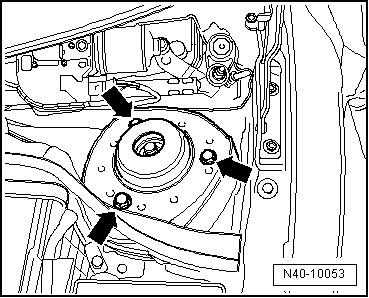
- Carefully lift the wheel bearing housing using the transmission jack enough so that the suspension strut/strut tower bolts - arrows - can be installed.
Pic 17
If necessary, use ladder, for example the Step Ladder (VAS5085) to install bolts.
- Tighten bolts for upper strut mounting - arrows -.
- Remove Engine/Gearbox Jack Adapter - Wheel Hub Support (T10149).
- Tighten threaded connection of wheel bearing housing/suspension strut - arrow -.
Pic 18
- Remove the nuts - arrows -.
Pic 19
- Insert drive axle into wheel hub.
- Insert wheel bearing housing with ball joint into control arm.
- Attach the ball joint to the control arm - arrows -.
Make sure that the ball joint boot is not damaged or twisted.
- Tighten drive axle bolt to wheel hub:
Twelve-point bolt with ribs, refer to => [ Drive Axle Twelve-Point Bolt with Ribs, Loosening and Tightening ] See: Axle Nut > Procedures > Drive Axle Twelve-Point Bolt With Ribs, Loosening and Tightening.
Twelve-point bolt without ribs, refer to => [ Drive Axle Twelve-Point Bolt without Ribs, Loosening and Tightening ] See: Axle Nut > Procedures > Drive Axle Twelve-Point Bolt Without Ribs, Loosening and Tightening.
Vehicle must not rest on wheels when doing so.
With bolt loosened, wheel bearing can be damaged by vehicle's own weight.
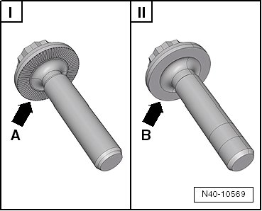
Differences Between a Twelve-Point Bolt with Ribs and a Twelve-Point Bolt without Ribs
pic 20
The contact surfaces - arrow A - and - arrow B - are different on the two-point bolts.
I Twelve-point bolt with ribs - arrow A -
II Twelve-point bolt without ribs - arrow B -
- Install plenum chamber cover.
- Install wiper arms.
Further installation is in the reverse sequence to removal.
- Install the wheel and tighten the wheel bolts. Refer to => [ Wheel Bolt Tightening Specification ] See: Wheel Stud / Lug Nut > Mechanical > Wheel Bolt Tightening Specification.
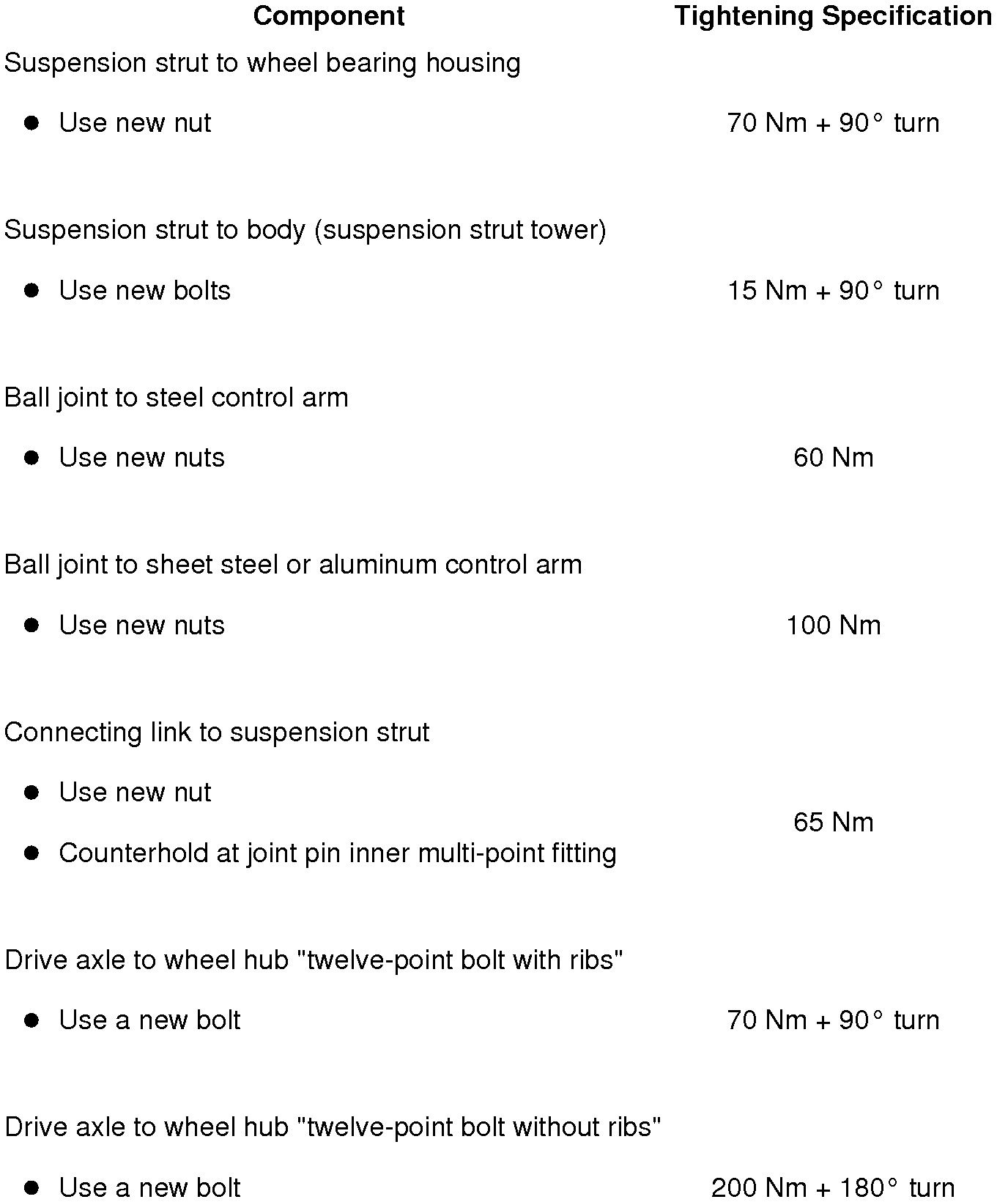
Tightening Specifications
pic 21
____________________________________
Let me know if you have other questions.
Take care,
Joe
Images (Click to make bigger)
Thursday, April 25th, 2019 AT 7:02 PM