Hi,
Here are the directions specific to your vehicle for timing belt replacement. It will guide you in properly setting the timing. The attached pics correlate with the directions.
_______________________________________
1989 Subaru Hatchback 4WD F4-1781cc 1.8L SOHC
Procedures
Vehicle Engine, Cooling and Exhaust Engine Timing Components Timing Belt Service and Repair Procedures
PROCEDURES
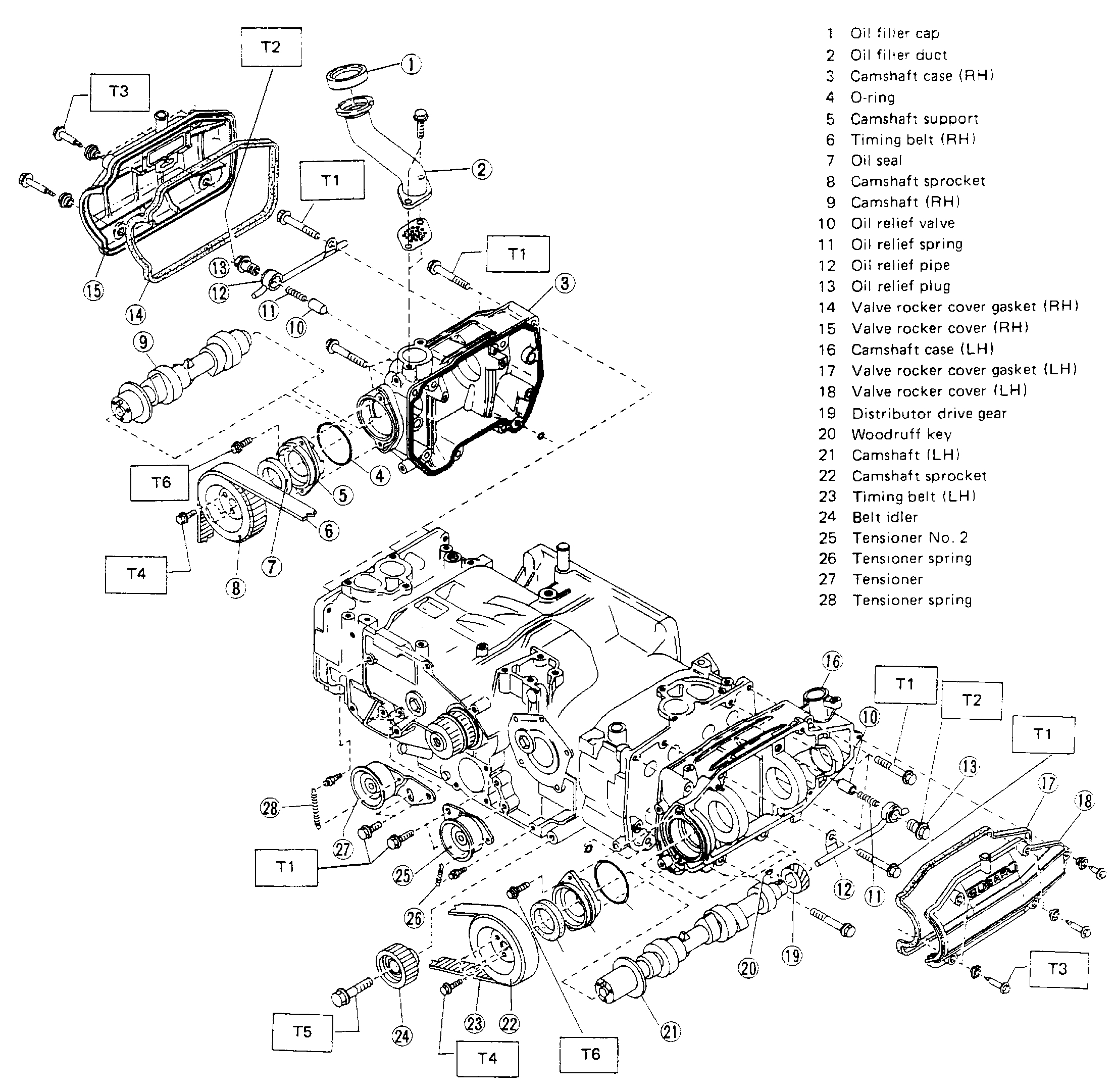
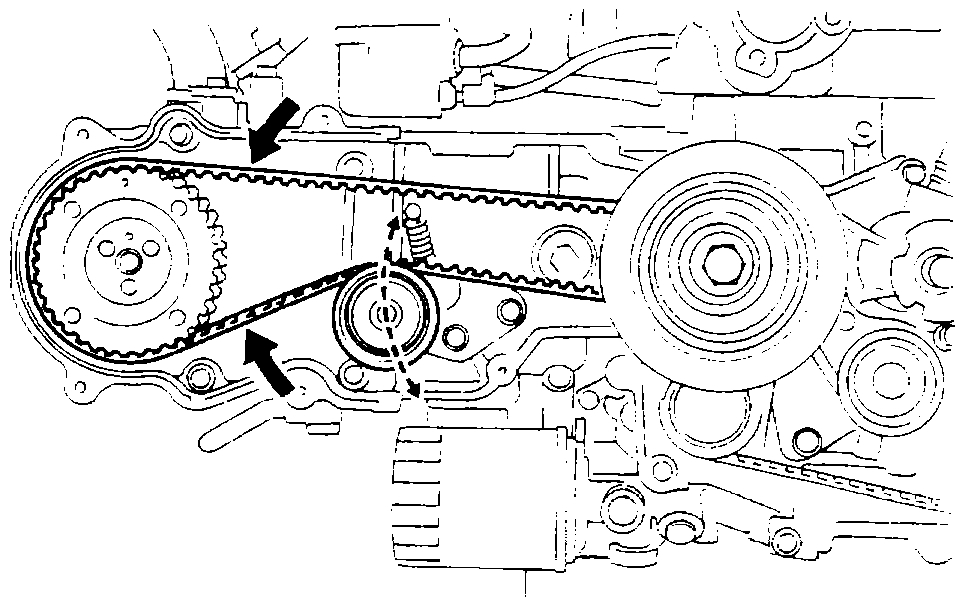
Camshaft And Timing Belt
pic 1
Tightening torque:
T1: 17.2 - 20.1 N-m (1.75 - 2.05 kg-m, 12.7 - 14.8 ft-lb).
T2: 23 - 26 N-m ( 2.3 - 2.7 kg-m, 17 - 20 ft-lb).
T3: 4.4 - 5.4 N-m (0.45 - 0.55 kg-m, 3.3 - 4.0 ft-lb).
T4: 9.1 - 10.5 N-m (0.93 - 1.07 kg-m, 6.7 - 7.7 ft-lb).
T5: 39 - 47 N-m (4.0 - 4.8 kg-m, 29 - 35 ft-lb).
T6: 6 - 7 N-m (0.6 - 0.7 kg-m, 4.3 - 5.1 ft-lb).
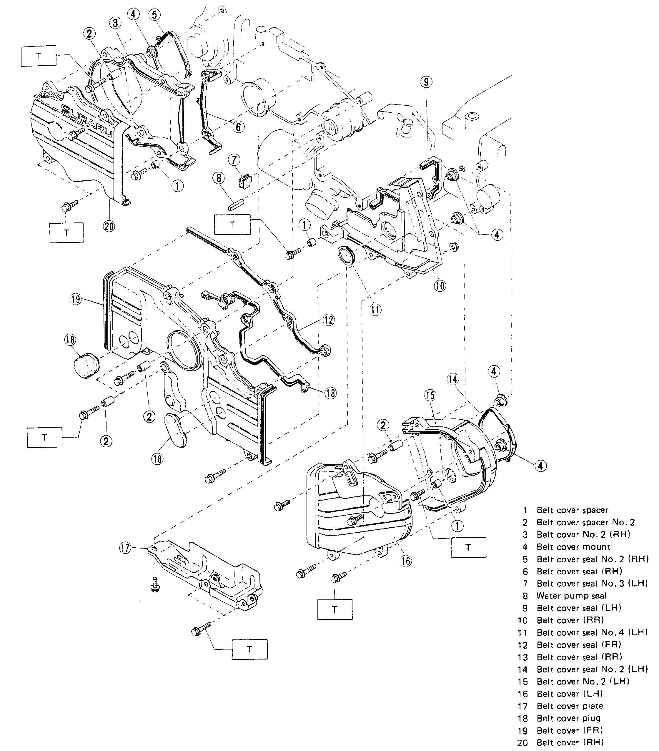
Belt Cover
pic 2
Tightening torque:
T: 4.4 - 5.4 N-m (0.45- 0.55 kg-m, 3.3 - 4.0 ft-lb).
REMOVAL
1. Loosen water pump pulley mounting nuts or bolts.
2. Loosen two alternator mounting bolts, and detach V-belt. [Except air conditioner equipped model]
3. Remove water pump pulley and pulley cover.
4. Disconnect lead from oil pressure switch.
5. Remove oil level gauge guide together with gauge.
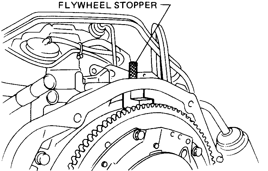
Pic 3
pic 4
6. Remove crankshaft pulley. To lock crankshaft, use FLYWHEEL STOPPER [manual transmission model] or DRIVE PLATE STOPPER [automatic transmission model].
7. Remove belt cover plate. [TURBO model]
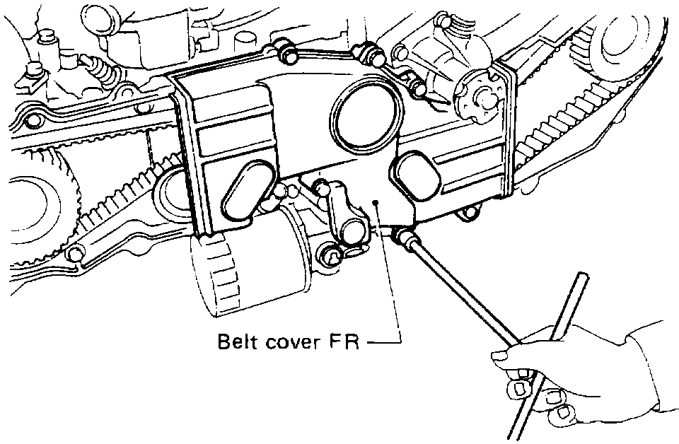
8. Remove belt covers LH, RH and FR.
Pic 5
9. Removing timing belt
(a)Loosen tensioner mounting bolts on # 1 cylinder by 1/2 turn.
(b)With tensioner fully turned to slacken belt, tighten mounting bolts.
(c)Mark rotating direction of timing belt, then remove belt.
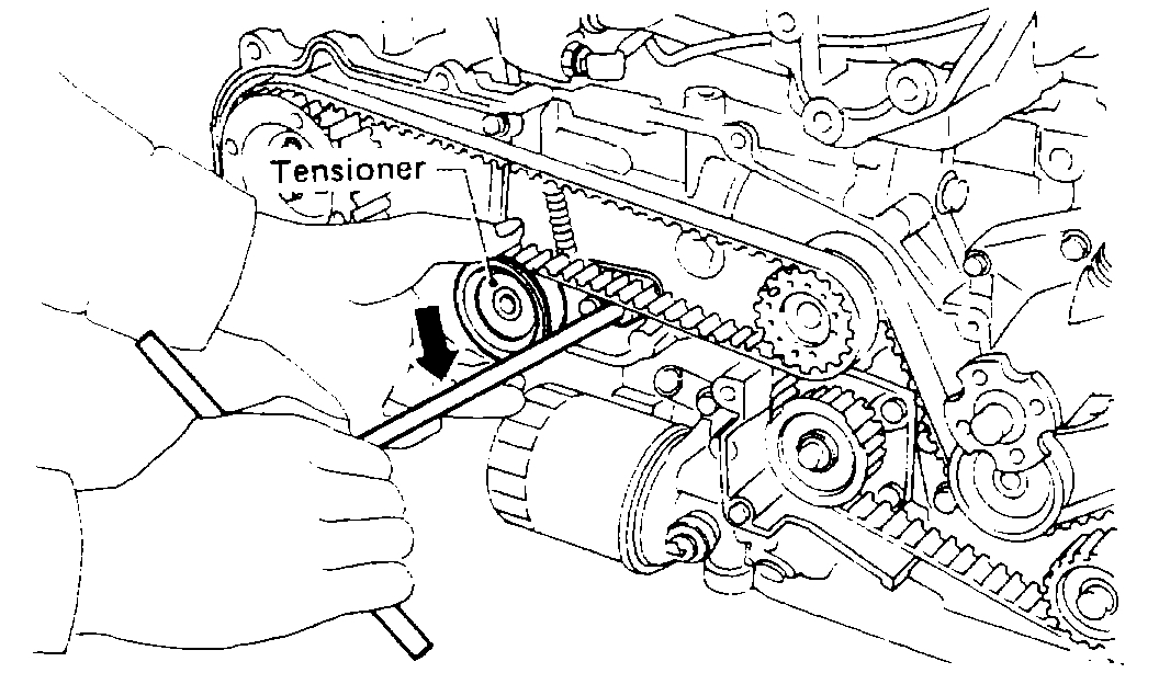
(d)Loosen tensioner No. 2 mounting bolts on # 2 cylinder by 1/2 turn.
(e)With tensioner fully rotated to slacken belt by using TENSIONER WRENCH, tighten tensioner mounting bolts.
NOTE: Cover TENSIONER WRENCH clamping tips with a rubber hose or waste cloth to prevent crankshaft or pulley from being damaged.
Pic 6
(f)Remove crankshaft sprocket.
(g)Remove timing belt after marking rotating direction of belt.
(h)Remove crankshaft sprocket No. 2.
10. Remove tensioner and tensioner No. 2 together with tensioner spring.
11. Remove belt idler.
Pic 7
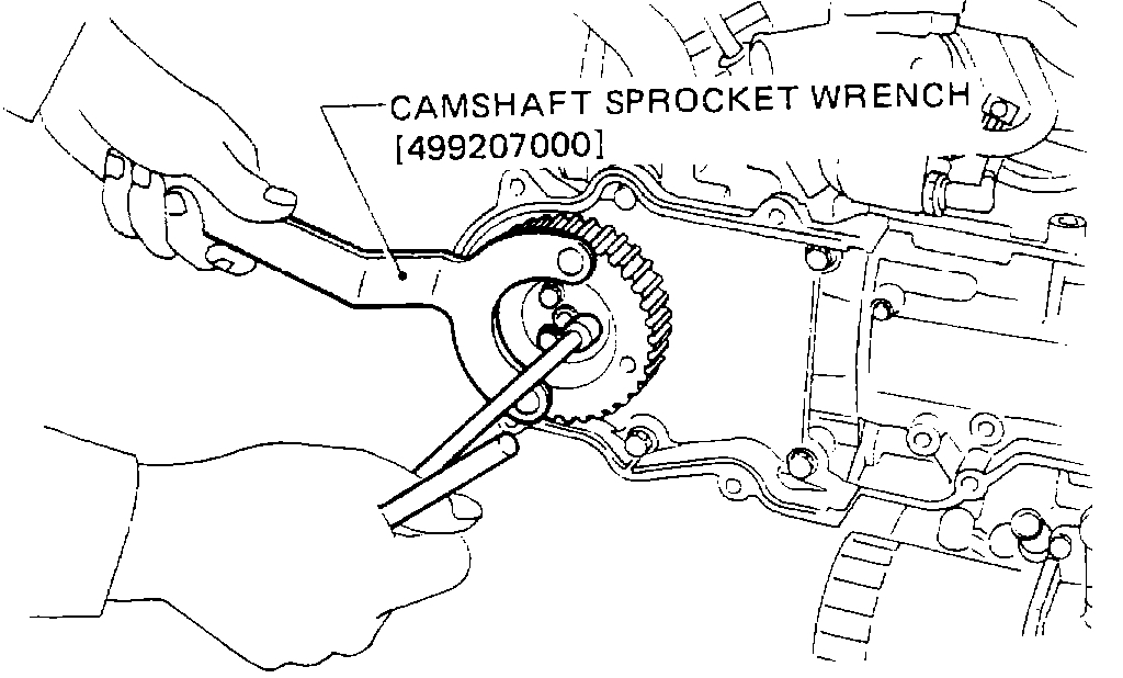
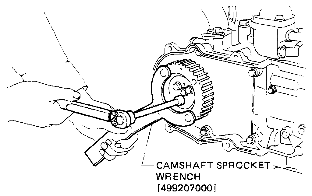
12. Remove camshaft sprockets by using CAMSHAFT SPROCKET WRENCH.
13. Remove right-hand belt cover No. 2, left-hand belt cover No. 2 and belt cover RR.
TIMING BELT
1. Check timing belt teeth for breaks, cracks, and wear. If any fault is found, replace belt.
2. Check the condition of back side of belt; if any crack is found, replace belt.
NOTE:
A. Be careful not to let oil, grease or coolant contact the belt. Remove quickly and thoroughly if this happens.
Pic 8
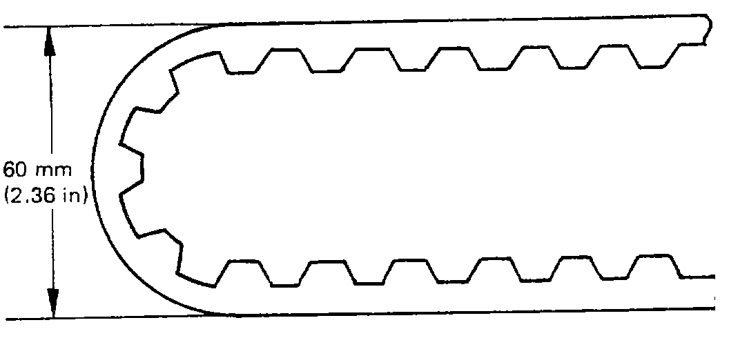
B. Do not bend the belt sharply. The bending radius must be greater than 60 mm (2.36 in).
C. When replacing belt, be sure to replace both belts as a matched set.
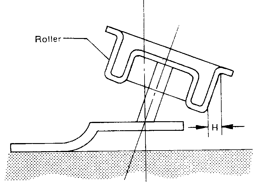
TIMING BELT TENSIONER
1. Check tensioner roller for smooth rotation. Replace roller if noise or excessive play is noted.
Pic 9
2. Measure the out-of-squareness of tensioner roller H. If it exceeds 0.5 mm (0.020 in), replace roller.
BELT IDLER
Check idler for smooth rotation. Replace if noise or excessive play is noted.
INSTALLATION
1. Install belt cover seal LH No. 3 to cylinder block.
2. Install belt cover LH seal, belt cover No.4 LH seal, and belt cover mount to belt cover RR, then install to cylinder block.
Tightening torque:
4.4 - 5.4 N-m (0.45 - 0.55 kg-m, 3.3 - 4.0 ft-lb).
3. Install belt cover No. 2 LH seal and belt cover mounts to belt cover No. 2 LH, then install to cylinder head and camshaft case.
Tightening torque:
4.4 - 5.4 N-m (0.45 - 0.55 kg-m, 3.3 - 4.0 ft-lb).
4. Install belt cover RH seal, belt cover No. 2 RH seal, and belt cover mounts to belt cover No. 2 RH, then install to cylinder head and camshaft case.
Tightening torque:
4.4 - 5.4 N-m (0.45 - 0.55 kg-m, 3.3 - 4.0 ft-lb).
Pic 10
5. Install camshaft sprockets to right and left camshafts. To lock camshaft, use CAMSHAFT SPROCKET WRENCH.
NOTE: Tighten bolts gradually in two or three steps until the specified torque is attained.
Tightening torque:
9.1 - 10.5 N-m (0.93-1.07 kg-m, 6.7 - 7.7 ft-lb).
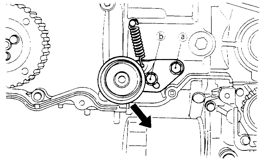
6. Installing tensioner
(a)Attach tensioner spring to tensioner, then install to cylinder block RH. Tighten bolts temporarily by hand.
(b)Attach tensioner spring to bolt, tighten bolt (A), and then loosen 1/2 turn.
Pic 11
(c)Push down tensioner until it stops, then tighten temporarily bolt (B).
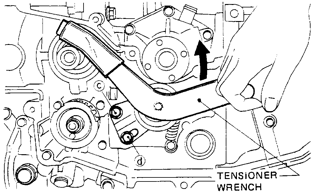
7. Installing tensioner No. 2
(a)Attach tensioner spring to tensioner No. 2, then install the tensioner No. 2 to cylinder block LH. Tighten bolts temporarily by hand.
(b)Attach tensioner spring to bolt, tighten bolt (C) then loosen 1/2 turn.
Pic 12
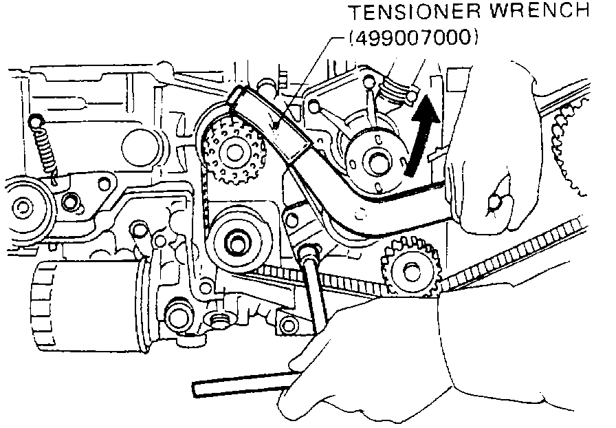
(c)Raise tensioner No. 2 using TENSIONER WRENCH (499007000) until it stops. Then tighten bolt (D) temporarily.
NOTE: Cover the tip of tensioner wrench with a rubber hose or waste cloth to prevent crankshaft or pulley from being damaged.
8. Install belt idler to cylinder block, using care not to turn over seal.
Tightening torque:
39 - 47 N-m (4.0 - 4.8 kg-m, 29 - 35 ft-lb).
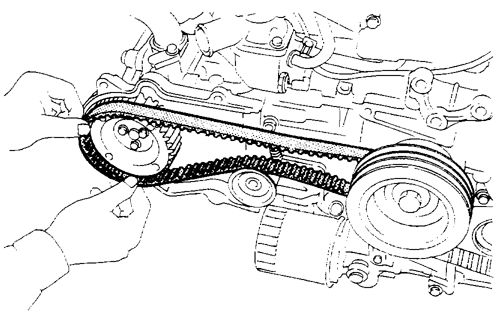
9. Install timing belt.
Pic 13
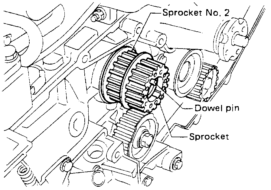
(a)Install sprocket No. 2 and sprocket to crankshaft.
NOTE: Sprocket No. 2 can be identified by the absence of dowel pin.
Pic 14
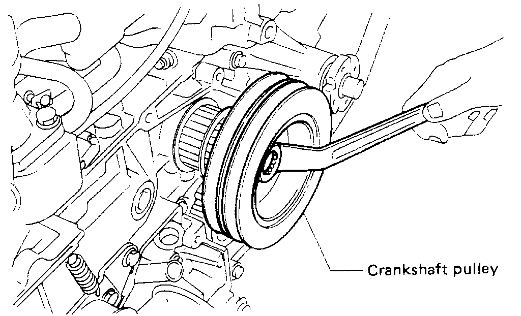
(b)Install crankshaft pulley to crankshaft, and tighten bolt temporarily.
Pic 15
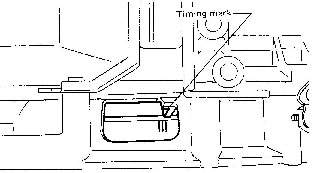
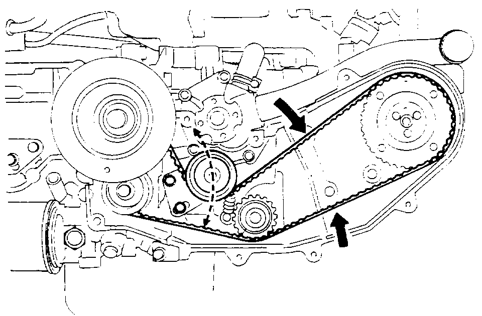
(c)Align the center of three lines scribed on the flywheel with timing mark on flywheel housing.
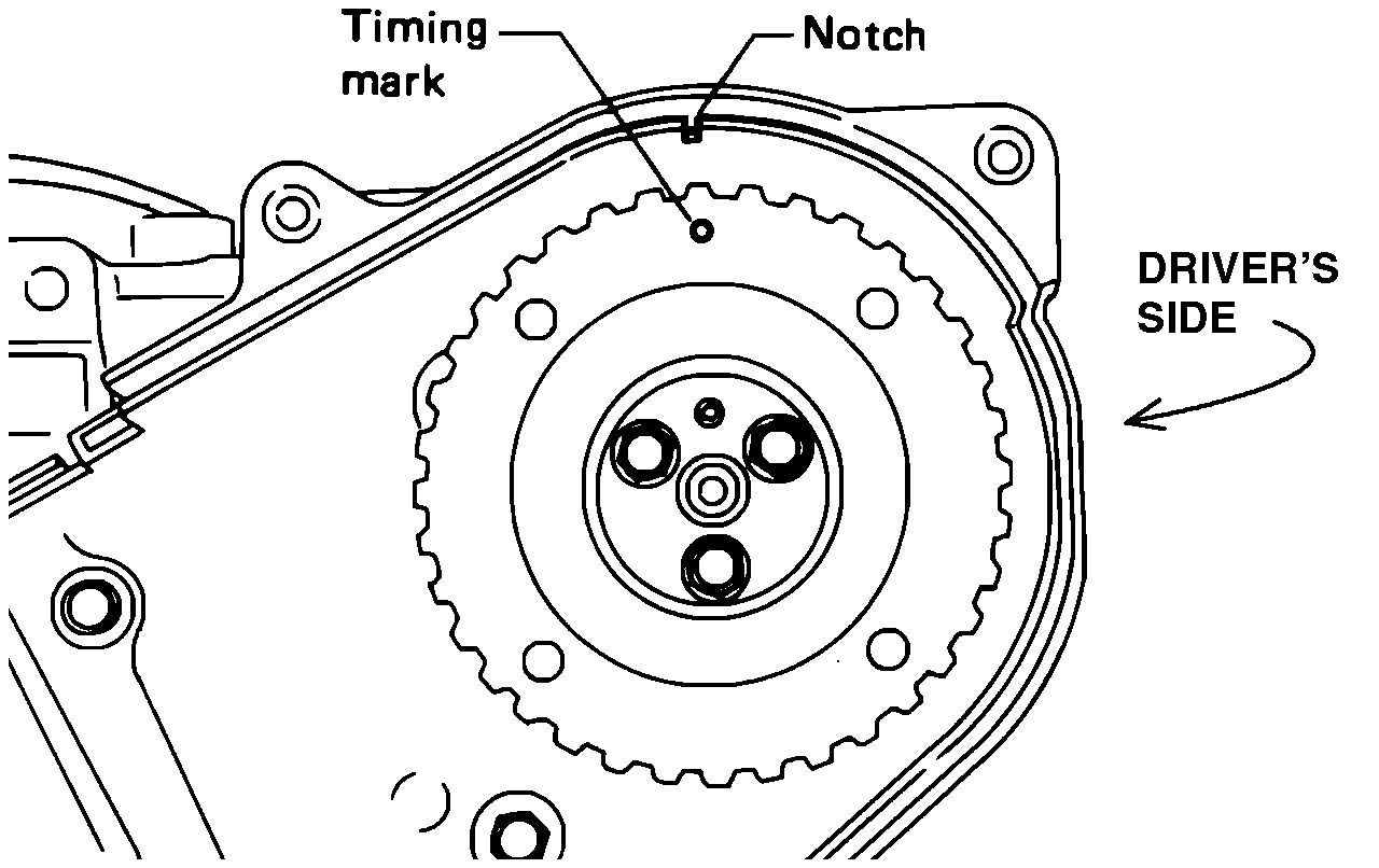
Camshaft Timing Marks, Left Side (DRIVER'S SIDE)
pic 16
(d)Align timing mark on camshaft sprocket LH with notch in belt cover.
Pic 17
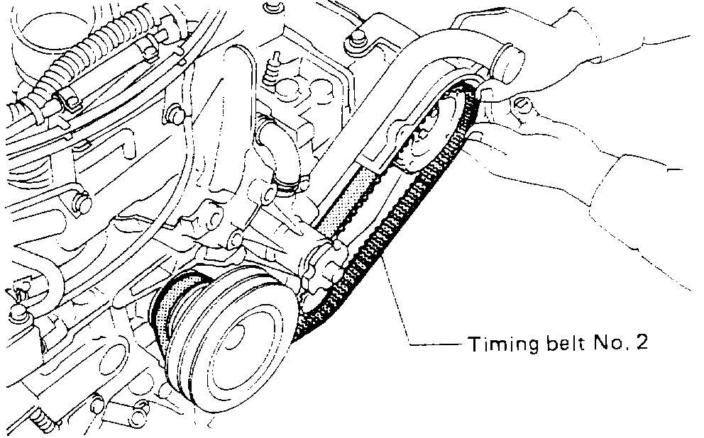
(e)Attach timing belt No. 2 to crankshaft sprocket No. 2, oil pump sprocket, belt idler, camshaft sprocket, in that order, avoiding downward slackening of the belt.
(6)Loosen tensioner No. 2 tightening bolt (D) by 1/2 turn to apply tension to belt.
Pic 18
(f)Push timing belt by hand to ensure smooth movement of tensioner.
Pic 19
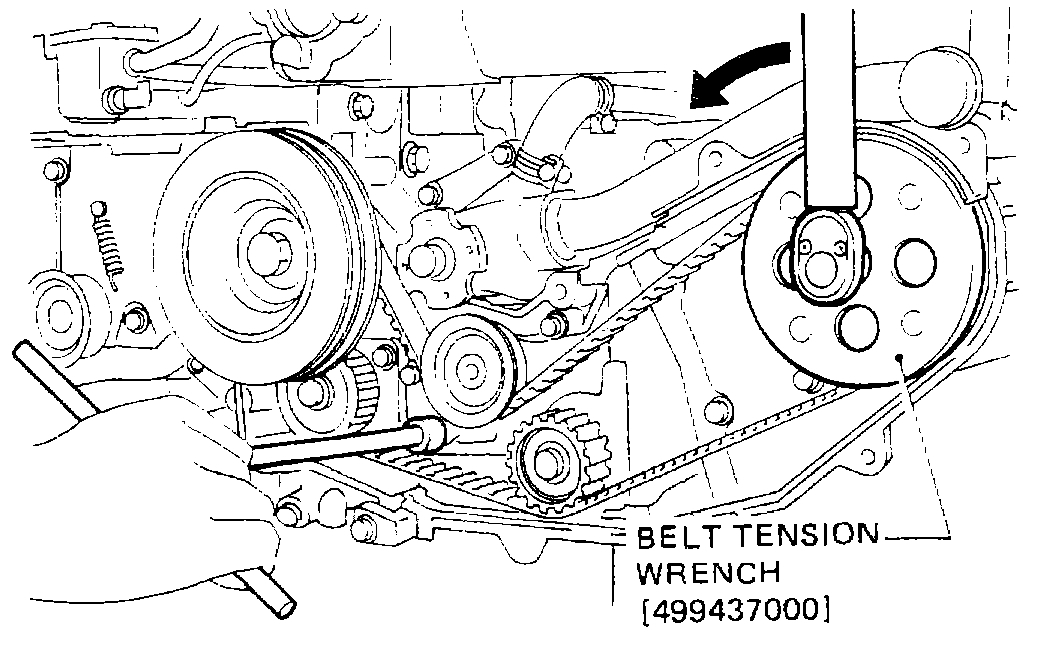
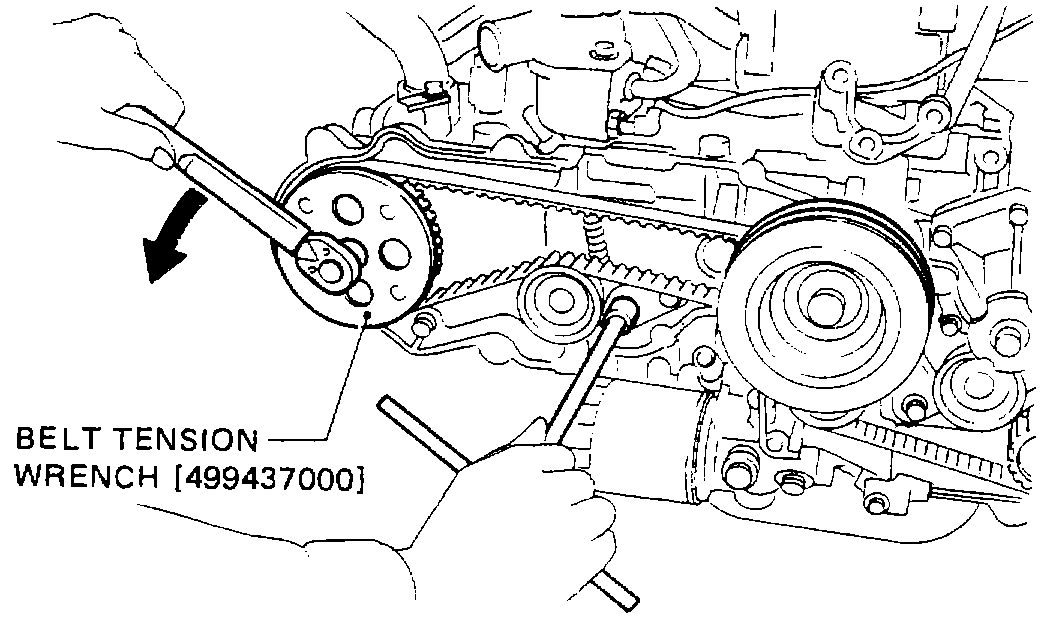
(g) Apply the specified torque to camshaft sprocket in counterclockwise direction using BELT TENSION WRENCH. While applying torque, tighten tensioner No. 2 bolt (D) temporarily, then tighten bolt (C) temporarily.
NOTE: When torquing sprocket, be extremely careful not to apply excessive force to it Excessive belt tension will greatly reduce belt life.
Belt Tension: 147 - 245 N-m (33 - 55 ft-lb).
Torque to cam sprocket: 24 - 25 N-m (18 ft-lb).
(h)Tighten bolt (D) and bolt (C) in that order, to the specified torque.
Tightening torque:
17.2 - 20.1 N-m (1.75 -2.05 kg-m, 12.7 - 14.8 ft-lb).
(i)Ascertain that flywheel timing mark and camshaft sprocket LH timing mark are in their normal positions.
(j)Turn crankshaft one turn clockwise from the position where timing belt No. 2 was installed, and align the center of three lines scribed on the flywheel with timing mark on flywheel housing.
Pic 20
(k)Align timing mark on camshaft sprocket RH with the notch in belt cover.
(l)Attach timing belt to crankshaft sprocket and camshaft sprocket, avoiding slackening of belt on the upper side.
Pic 21
(m)Loosen tensioner bolt (B) 1/2 turn to apply tension to belt.
Pic 22
(n)Push timing belt by hand to ensure smooth tensioner movement.
Pic 23
(o)Apply the specified torque (same as camshaft sprocket LH) to camshaft sprocket RH in counterclockwise direction using BELT TENSION WRENCH. While applying torque, tighten tensioner No. 2 bolt 3 b. Temporarily, then tighten bolt a temporarily.
(p)Tighten bolt (B) and bolt (A) in that order, to the specified torque.
Tightening torque:
17.2 - 20.1 N-m (1.75 - 2.05 kg-m, 12.7 - 14.8 ft-lb).
(q)Make sure that flywheel timing mark and camshaft sprocket RH timing mark are in their normal positions.
(r)Remove crankshaft pulley.
NOTE: Do not remove sprocket with crankshaft pulley.
Pic 24
10. Install belt cover FR seal, belt cover RR seal, and belt cover plug to belt cover FR, then install belt cover FR to cylinder block.
NOTE: Before installing belt cover, ensure that no foreign matter such as nut or washer is in it.
11. Install belt covers LH and RH.
12. Install belt cover plate. TURBO model]
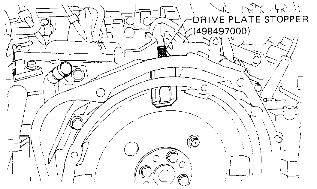
13. Install crank pulley to crankshaft using FLYWHEEL STOPPER (498277000) [manual transmission model] or DRIVE PLATE STOPPER (498497000) [automatic transmission model] to lock crankshaft.
Tightening torque:
89 - 107 N-m (9.1 - 10.9 kg-m, 66 - 79 ft-lb).
14. Install water pump pulley and pulley cover to water pump assembly, and tighten nuts temporarily.
15. Install oil level gauge and gauge guide. Apply engine oil to 0-ring beforehand.
16. Connect lead to oil pressure switch.
17. Install V-belt and apply proper tension to the belt.
18. Tighten water pump pulley mounting nuts or bolts to the specified torque.
Tightening torque:
9.1 - 10.5 N-m (0.93 - 1.07 kg-m, 6.7 - 7.7 ft-lb).
_____________________________________
I hope this helps. Let me know if you have other questions.
Take care,
Joe
Images (Click to make bigger)
Wednesday, March 25th, 2020 AT 11:56 PM