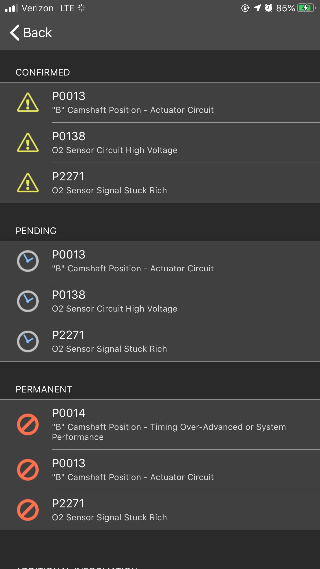
Okay, below is the flow chart for the 13 and 14.
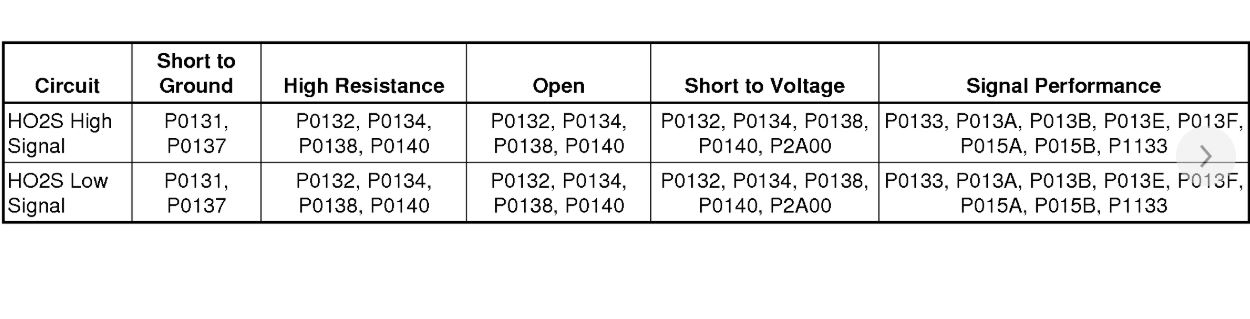
As far as the 138, I attached that as well for you to check.
Roy
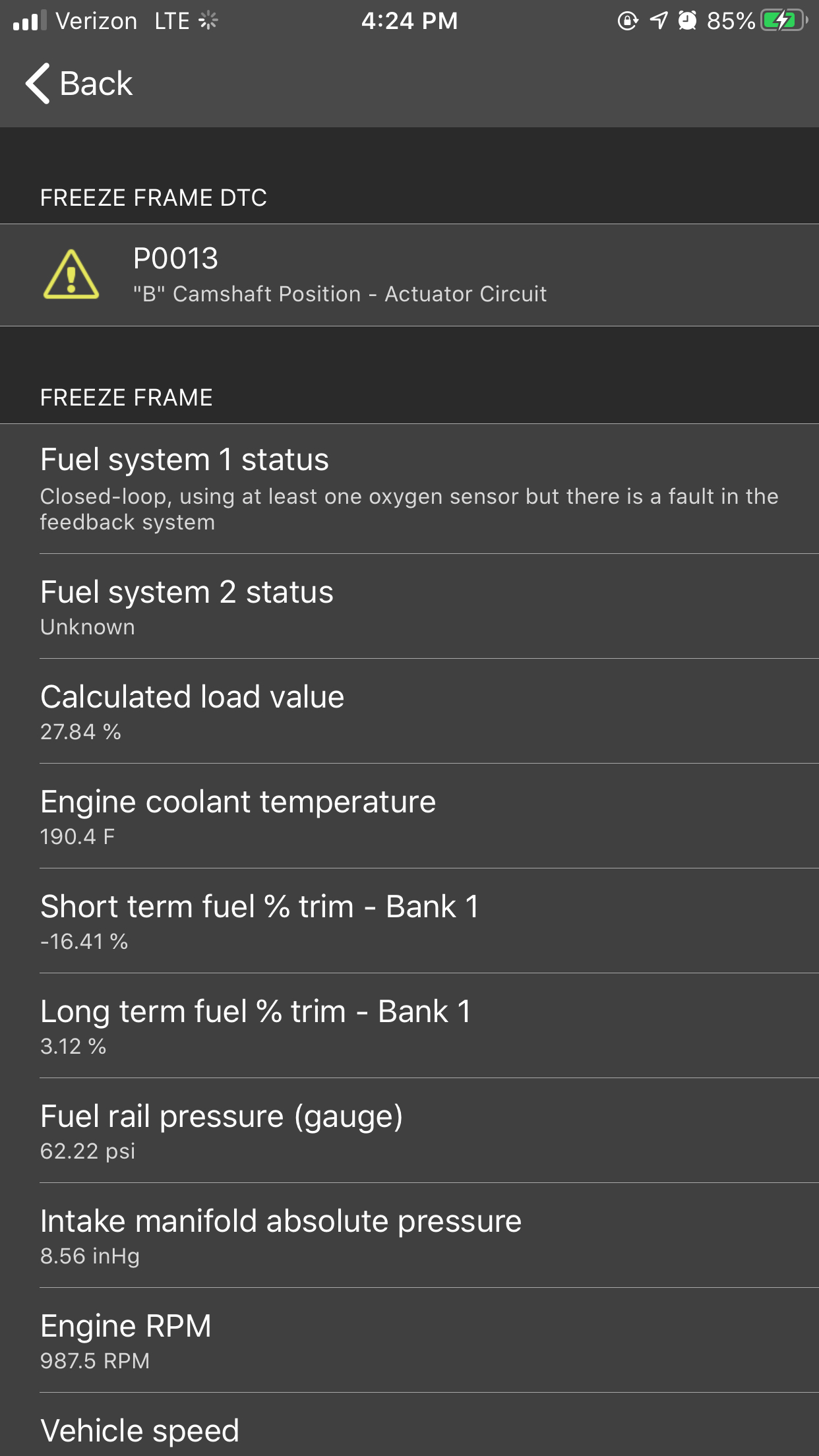
DTC P0010 or P0013
Diagnostic Instructions
Perform the Diagnostic System Check - Vehicle See: Vehicle > Initial Inspection and Diagnostic Overview > Diagnostic System Check - Vehicle prior to using this diagnostic procedure.
Review Strategy Based Diagnosis See: Vehicle > Initial Inspection and Diagnostic Overview > Strategy Based Diagnosis for an overview of the diagnostic approach.
Diagnostic Procedure Instructions See: Vehicle > Initial Inspection and Diagnostic Overview > Diagnostic Procedure Instructions provides an overview of each diagnostic category.
DTC Descriptors
DTC P0010
Intake Camshaft Position Actuator Solenoid Valve Control Circuit
DTC P0013
Exhaust Camshaft Position Actuator Solenoid Valve Control Circuit
Circuit/System Description
The camshaft position actuator system enables the engine control module (ECM) to change the timing of the camshafts while the engine is operating. The camshaft position actuator solenoid valve signal from the ECM is pulse width modulated (PWM). The ECM controls the camshaft position actuator solenoid valve duty cycle by controlling the amount of solenoid valve ON time. The camshaft position actuator solenoid valve controls the advance or the retard of each camshaft. The camshaft position actuator solenoid valve controls the oil flow that applies the pressure to advance or retard the camshafts.
The ECM controls the camshaft position actuator solenoid valve by supplying a 12 V pulse width modulated (PWM) signal. The ECM supplies a ground to the low reference circuit.
Conditions for Running the DTC
The ignition voltage is greater than 11 V.
The ECM has commanded the camshaft position actuator solenoid valve ON.
DTCs P0010 and P0013 run continuously once the above conditions are met.
Conditions for Setting the DTC
The ECM detects that the commanded state of the driver and the actual state of the control circuit do not match for greater than 5 s.
Action Taken When the DTC Sets
DTCs P0010 and P0013 are type B DTCs.
Conditions for Clearing the DTC
DTCs P0010 and P0013 are type B DTCs.
Diagnostic Aids
If the condition is intermittent, move the related harnesses and connectors, with the engine operating, while monitoring the scan tool circuit status parameters for the component. The circuit status parameters change from OK or Not Run to Malfunction if there is a condition with the circuit or a connection.
Reference Information
Schematic Reference
Engine Controls Schematics See: Powertrain Management > Electrical > Engine Controls Schematics
Connector End View Reference
Component Connector End Views See: Vehicle > Connector Views > Sunshade - Left Front
Description and Operation
Camshaft Actuator System Description See: Variable Valve Timing Actuator > Components Camshaft Actuator System Description
Electrical Information Reference
Circuit Testing See: Vehicle > Component Tests and General Diagnostics > Circuit Testing
Connector Repairs See: Vehicle > Component Tests and General Diagnostics > Connector Repairs
Testing for Intermittent Conditions and Poor Connections See: Vehicle > Component Tests and General Diagnostics > Testing for Intermittent Conditions and Poor Connections
Wiring Repairs See: Vehicle > Component Tests and General Diagnostics > Wiring Repairs
DTC Type Reference
Powertrain Diagnostic Trouble Code (DTC) Type Definitions See: A L L Diagnostic Trouble Codes ( DTC ) > Diagnostic Trouble Code Descriptions > Powertrain Diagnostic Trouble Code (DTC) Type Definitions
Scan Tool Reference
Control Module References See: Vehicle > Programming and Relearning > Control Module References for scan tool information
Circuit/System Verification
Note:
If a crankshaft or camshaft position sensor DTC is set, the Camshaft Position Actuator output control will not function.
1. Ignition ON, observe the DTC information with a scan tool. Verify DTC P0335, P0336, P0340, and P0341 is not set.
If any of the DTCs are set, refer to Diagnostic Trouble Code (DTC) List - Vehicle See: A L L Diagnostic Trouble Codes ( DTC ) > Diagnostic Trouble Code Descriptions > Diagnostic Trouble Code (DTC) List - Vehicle for further diagnosis.
2. Observe the appropriate control circuit status parameters listed below with a scan tool:
The Exhaust/Intake Camshaft Position Actuator Solenoid Valve Control Circuit Open test status
The Exhaust/Intake Camshaft Position Actuator Solenoid Valve Control Circuit High Voltage test status
The Exhaust/Intake Camshaft Position Actuator Solenoid Valve Control Circuit Low Voltage test status
Each parameter should display OK or Not Run
3. Engine idling, command the Camshaft Position Actuator to 20° while observing the following control circuit status parameters with a scan tool:
The Exhaust/Intake Camshaft Position Actuator Solenoid Valve Control Circuit Open test status
The Exhaust/Intake Camshaft Position Actuator Solenoid Valve Control Circuit High Voltage test status
The Exhaust/Intake Camshaft Position Actuator Solenoid Valve Control Circuit Low Voltage test status
Each parameter should display OK or Not Run
4. Engine at normal operating temperature, raise the engine speed to 2,000 RPM for 10 s. DTC P0010 or P0013 should not set.
5. Operate the vehicle within the Conditions for Running the DTC to verify the DTC does not reset. You may also operate the vehicle within the conditions that you observed from the Freeze Frame/Failure Records data.
Circuit/System Testing
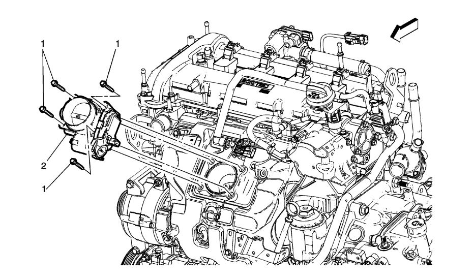
1. Ignition OFF, disconnect the harness connector at the appropriate Q6 camshaft position actuator solenoid valve.
Note:
A test lamp must be used for this test. The control circuit is pulled-up to a low current voltage, 1.5-4.5 V on the control circuit is normal.
2. Ignition ON, verify that a test lamp does not illuminate between the control circuit terminal A and ground.
If the test lamp illuminates, test the control circuit for a short to voltage. If the circuit tests normal, replace the K20 ECM.
3. Ignition OFF and all vehicle systems OFF. It may take up to 2 minutes for all vehicle systems to power down. Test for less than 5 ohms between the low reference circuit terminal B and ground.
If greater than the specified value, test the low reference circuit for an open/high resistance. If the circuit tests normal, replace the K20 ECM.
4. Ignition ON, connect the DMM black lead to the control circuit terminal A. Connect the DMM red lead to B+. Set the DMM on the diode setting. Command the CMP actuator solenoid ON and OFF with a scan tool. The DMM should transition from OL when commanded OFF to less than 1 V when commanded ON.
If the circuit voltage does not correspond to the specified values, test the control circuit for an open/high resistance or a short to ground. If the circuit tests normal, replace the K20 ECM.
5. If all circuits/connections test normal, test or replace the appropriate Q6 camshaft position actuator solenoid valve.
Component Testing
1. Ignition OFF, disconnect the harness connector at the appropriate Q6 camshaft position actuator solenoid valve.
2. Test for 8-13 ohms between the control terminal A and the low reference circuit terminal B of the Q6 camshaft position actuator solenoid valve.
If not within the specified range, replace the Q6 camshaft position actuator solenoid valve.
3. Test for infinite resistance between each terminal and the Q6 camshaft position actuator solenoid valve housing.
If not the specified value, replace the Q6 camshaft position actuator solenoid valve.
Repair Instructions
Perform the Diagnostic Repair Verification See: A L L Diagnostic Trouble Codes ( DTC ) > Verification Tests > Diagnostic Repair Verification after completing the repair.
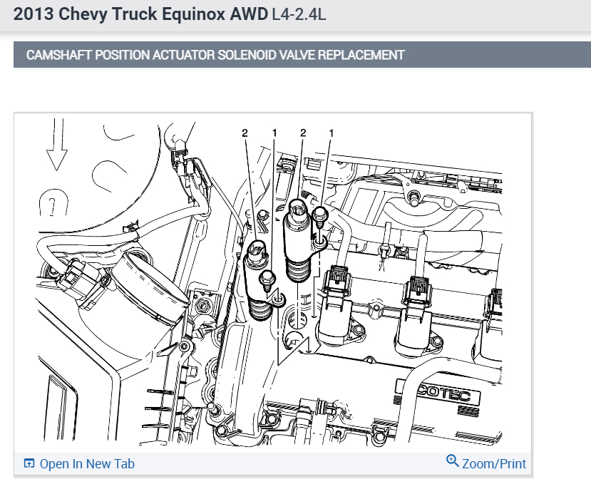
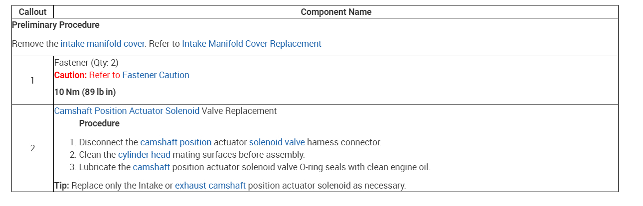
Camshaft Position Actuator Solenoid Valve Replacement See: Variable Valve Timing Solenoid > Removal and Replacement > Camshaft Position Actuator Solenoid Valve Replacement
Control Module References See: Vehicle > Programming and Relearning > Control Module References for engine control module replacement, programming, and setup
138
Scan Tool Reference
Control Module References See: Vehicle > Programming and Relearning > Control Module References for scan tool information
Circuit/System Verification
1. Ignition ON, observe the DTC information with a scan tool. Verify no B52 HO2S heater DTCs are set.
If a B52 HO2S heater DTC is set, refer to Diagnostic Trouble Code (DTC) List - Vehicle See: A L L Diagnostic Trouble Codes ( DTC ) > Diagnostic Trouble Code Descriptions > Diagnostic Trouble Code (DTC) List - Vehicle.
2. Engine running, observe the appropriate scan tool B52 HO2S voltage parameter. The reading should be within the range of 50-1,050 mV.
3. Operate the vehicle within the Conditions for Running the DTC to verify the DTC does not reset. You may also operate the vehicle within the conditions that you observed from the Freeze Frame/Failure Records data.
Circuit/System Testing
1. Ignition OFF, disconnect the appropriate B52 HO2S harness connector.
2. Ignition ON, observe the appropriate scan tool HO2S voltage parameter. The parameter should display approximately 1.9 V.
If less than the specified range, test the high and low signal circuits for a short to ground. If both signal circuit test normal, replace the K20 ECM.
3. Ignition ON, test for 2.5-3.0 V between the high signal circuit terminal B and ground.
If less than the specified range, test the high signal circuit for an open/high resistance. If the circuit tests normal, replace the K20 ECM.
If greater than the specified range, test the high signal circuit for a short to voltage. If the circuit tests normal, replace the K20 ECM.
4. Ignition OFF, connect a 3 A fused jumper wire between the high signal circuit terminal B and the low signal circuit terminal A.
Note: The low signal circuit is tied to a pull-up circuit within the ECM. A voltage of 0.90-1.10 V on the low signal circuit is normal.
5. Ignition ON, verify the scan tool HO2S parameter displays 0.0 V.
If greater than the specified range, test the low signal circuit for an open/high resistance or for a short to voltage. If the circuit tests normal, replace the K20 ECM.
6. If all circuits test normal, test or replace the appropriate B52 HO2S.
Repair Instructions
Perform the Diagnostic Repair Verification See: A L L Diagnostic Trouble Codes ( DTC ) > Verification Tests > Diagnostic Repair Verification after completing the repair.
Heated Oxygen Sensor Replacement - Sensor 1 See: Oxygen Sensor > Removal and Replacement > Heated Oxygen Sensor Replacement - Sensor 1
Heated Oxygen Sensor Replacement - Sensor 2 See: Oxygen Sensor > Removal and Replacement > Heated Oxygen Sensor Replacement - Sensor 2
Perform the scan tool Heated Oxygen Sensor Resistance Learn Reset after replacing a HO2S.
Control Module References See: Vehicle > Programming and Relearning > Control Module References for engine control module (ECM) replacement, programming and setup.
Nov 6, 2019 at 1:56 PM